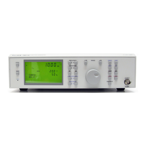
Fluke 6080A User manual

6080A/AN
SYNTHESIZED SIGNAL GENERATOR
ServiceManual
P/N868906
October1989
©1989,JohnFlukeMfg.Co.Inc.AllrightsreservedPOBoxC9090EverettWA98206
Advanced Test Equipment Rentals
www.atecorp.com 800-404-ATEC (2832)
®
E
s
t
a
b
l
i
s
h
e
d
1
9
8
1

WARRANTY
TheJOHNFLUKEMFG.CO.,INCwarrantseachinstrumentitmanufacturestobefreefromdefectsin
materialandworkmanshipundernormalusefor2 yearsfromthedateofpurchase.Thiswarrantyextends
onlytotheoriginalpurchaser.Thiswarrantyshallnotapplytofuses,disposablebatteries,oranyproductor
partsthathavebeensubjecttomisuse,neglect,accident,orabnormalconditionsofoperation.
Intheeventoffailureofa productcoveredbythiswarranty,JOHNFLUKEMFG.CO.,INCwillrepairand
calibrateaninstrumentreturnedtoanauthorizedServiceCenterwithin2 years oftheoriginalpurchase;
providedthewarrantor'sexaminationdisclosestoitssatisfactionthattheproductwasdefective.The
warrantormay,atitsoption,replacetheproductinlieuofrepair.Withregardtoanyinstrumentreturned
within2 yearsoftheoriginalpurchase,saidrepairsorreplacementwillbemadewithoutcharge.Ifthefailure
hasbeencausedbymisuse,neglect,accident,orabnormalconditionsofoperation,repairswillbebilledata
nominalcost.Insuchcase,anestimatewillbesubmittedbeforeworkisstatedifrequested.
Ifanyfailureoccurs,thefollowingstepsshouldbetaken:
1.NotifytheJOHNFLUKEMFG.CO.,INCornearestServiceCenter,givingfulldetailsofthe
difficulty.Includethemodelnumber,typenumber,andserialnumber.
Onreceiptofthisinformation,servicedataorshippinginstructionswillbeforwardedtoyou.
2.Onreceiptoftheshippinginstructions,forwardtheinstrument,transportationprepaid.
RepairswillbemadeattheServiceCenterandtheinstrumentwillbereturnedprepaid.
SHIPPINGTOMANUFACTURERFORREPAIRORADJUSTMENT
AllshipmentofJOHNFLUKEMFG.CO.,INCinstrumentsshouldbeshippedintheoriginalpackingcarton(if
available).Iftheoriginalcartonisnotavailable,useanysuitablecontainerthatisrigidandofadequatesize.If
asubstitutecontainerisused,theinstrumentshouldbewrappedinpaperandsurroundedwithatleastfour
inchesofshock-absorbingmaterial.

TableofContents
SECTIONTITLEPAGE
1INTRODUCTIONANDSPECIFICATIONS1-1
1-1.INTRODUCTION1-1
1-2.UNPACKINGTHESIGNALGENERATOR1-1
1-3.SAFETY1-2
1-4.ACCESSORIES1-3
1-5.SIGNALGENERATORSPECIFICATIONS1-3
2THEORYOFOPERATION2-1
2-1.INTRODUCTION2-1
2-2.GENERALDESCRIPTION2-1
2-3.FrontPanelSection2-2
2-4.Upper/LowerModuleSections2-2
2-5.RearPanelSection2-2
2-6.FUNCTIONALDESCRIPTION2-2
2-7.Frequency2-2
2-8.FrequencyModulation2-4
2-9.PhaseModulation2-4
2-10.Output/LevelControl2-5
2-11.AmplitudeModulation2-5
2-12.PulseModulation2-5
2-13.InternalModulationOscillator2-6
2-14.PowerSupplyDescription2-6
2-15.DIGITALCONTROLLERSOFTWAREDESCRIPTION2-6
2-16.UserInterface2-6
2-17.Calibration/CompensationMemory2-7
2-18.Self-Test2-7
2-19.StatusSignals2-7
3CLOSED-CASECALIBRATION3-1
3-1.INTRODUCTION3-1
3-2.FrontPanelCalibration3-2
3-3.RemoteCalibration3-2
3-4.CalibrationData3-3
3-5.AMCALIBRATION3-4
3-6.FrontPanelAM CalibrationProcedure3-4
3-7.RemoteAMCalibrationProcedure3-6
i
(continued on page ii)

TABLEOFCONTENTS,continued
SECTIONTITLEPAGE
3-8.FMCALIBRATION3-7
3-9.FrontPanelFMCalibrationProcedure3-8
3-10.RemoteFMCalibration3-9
3-11.RFLEVELCALIBRATION3-10
3-12.FrontPanelLevelCalibrationProcedure3-11
3-13.RemoteLevelCalibrationProcedure3-13
3-14.REFERENCEOSCILLATORCALIBRATION3-14
3-15.FrontPanelReferenceOscillatorCalibrationProcedure3-15
3-16.RemoteReferenceOscillatorCalibrationProcedure3-16
4PERFORMANCETESTS4-1
4-1.INTRODUCTION4-1
4-2.TESTEQUIPMENT4-1
4-3.POWER-ONTEST4-4
4-4.FREQUENCYACCURACYTEST4-5
4-5.SYNTHESISTEST4-5
4-6.HIGH-LEVELACCURACYTEST4-6
4-7.MID-LEVELACCURACYTEST4-8
4-8.LOW-LEVELACCURACYTEST4-9
4-9.ALTERNATE-LEVELACCURACYTEST4-10
4-10.FLATNESSTEST4-13
4-11.OUTPUTLEAKAGETEST4-14
4-12.HARMONICANDLINE-RELATEDSPURIOUSTEST4-15
4-13.PHASENOISEANDNON-HARMONICSPURIOUSTESTS4-16
4-14.MODULATIONTESTS4-17
4-15.VOLTAGESTANDING-WAVERATIO(VSWR)TESTS4-23
4-16.PULSETESTS4-24
5ACCESSPROCEDURES5-1
5-1.INTRODUCTIONANDSAFETY5-1
5-2.LOCATIONOFMAJORASSEMBLIES5-3
5-3.ACCESSINSTRUCTIONS5-3
5-4.RemovingtheFrontPanelSection5-3
5-5.RemovingtheRearPanelSection5-3
5-6.RemovingtheA2CoarseLoopPCA5-4
5-7.RemovingtheA3 Sub-SynthesizerVCOPCA5-4
5-8.RemovingtheA4Sub-SynthesizerPCA5-5
5-9.RemovingtheA5 CoarseLoopVCOPCA5-5
5-10.RemovingtheA6ModOscillator PCA5-5
5-11.RemovingtheA8OutputPCA5-5
5-12.RemovingtheA9SumLoopVCOPCA5-6
5-13.RemovingtheA10PremodulatorPCA5-6
5-14.RemovingtheA11ModulationControlPCA5-6
5-15.RemovingtheA12SumLoopPCA5-7
5-16.RemovingtheA13ControllerPCA5-7
5-17.RemovingtheA14FMPCA5-8
5-18.RemovingtheA20Attenuator/RPPAssembly5-8
5-19.RemovingtheA22DelayCableAssembly5-8
ii
(continued on page iii)

TABLEOFCONTENTS,continued
SECTIONTITLEPAGE
6CIRCUITDESCRIPTIONS,TROUBLESHOOTING,ANDALIGNMENT6-1
6-1.INTRODUCTION6-1
6-2.MODULEREPLACEMENT6-4
6-3.A1DisplayPCA6-5
6-4.A2CoarseLoopPCA6-5
6-5.A3Sub-SynthesizerPCA6-5
6-6.A4Sub-SynthesizerPCA6-5
6-7.A5CoarseLoopVCOPCA6-5
6-8.A6ModOscillatorPCA6-5
6-9.A7RelayDriverPCA6-5
6-10.A8OutputPCA6-5
6-11.A9SumLoopVCOPCA6-5
6-12.A10PremodulatorPCA6-6
6-13.A11ModulationControlPCA6-6
6-14.A12SumLoopPCA6-6
6-15.A13ControllerPCA6-6
6-16.A14FMBoardPCA6-6
6-17.A15PowerSupplyPCA6-6
6-18.A19SwitchPCA6-6
6-19.A20Attenuator/RPPAssembly(A7,A21,A30)6-6
6-20.A22DelayLineAssembly(A25+A26+DelayCable+TrimCable).......6-6
6-21.UPDATINGCOMPENSATIONMEMORYWITH
MODULEEXCHANGEDATA6-7
6-22.PARTSREPLACEMENT6-8
6-23.SELF-TESTDESCRIPTION6-8
6-24.DigitalTests6-8
6-25.AMTests6-9
6-26.FMTests6-9
6-27.øMTests6-9
6-28.DCFMTest6-10
6-29.CoarseLoopTests6-11
6-30.Sub-SynthesizerTests6-11
6-31.SumLoopTests6-11
6-32.RFOutputTests6-12
6-33.PulseModulatorTests6-12
6-34.FilterTests6-12
6-35.STATUSSIGNALSANDSTATUSCODES6-13
6-36.SOFTWAREDIAGNOSTICFUNCTIONS6-14
6-37.DigitalControlLatchTest6-14
6-38.InstrumentDiagnosticState6-14
6-39.SetInternalDACs6-14
6-40.DisplaySynthesizerLoopFrequencies6-15
6APOWERSUPPLY6A-1
6A-1.POWERSUPPLYBLOCKDIAGRAM6A-1
6A-2.POWERSUPPLYCIRCUITDESCRIPTION6A-1
6A-3.POWERSUPPLYTROUBLESHOOTING6A-4
6A-4.TroubleshootingProcedure6A-4
6A-5.POWERSUPPLYADJUSTMENTPROCEDURE6A-5
iii
(continued on page iv)

TABLEOFCONTENTS,continued
SECTIONTITLEPAGE
6BDIGITALCONTROLLER6B-1
6B-1.DIGITALCONTROLLERBLOCKDIAGRAM6B-1
6B-2.DIGITALCONTROLLERCIRCUITDESCRIPTION(A13)6B-1
6B-3.Microprocessor6B-1
6B-4.Memory6B-1
6B-5.MemoryControl6B-3
6B-6.FrontPanelInterface6B-3
6B-7.IEEE-488Interface6B-3
6B-8.AttenuatorControlInterface6B-3
6B-9.ModuleI/O6B-3
6B-10.StatusandControl6B-4
6B-11.DIGITALCONTROLLERTROUBLESHOOTING6B-4
6B-12.RFControl6B-4
6B-13.MicroprocessorKernel6B-5
6B-14.Clock6B-5
6B-15.Power-OnReset6B-5
6B-16.UnusedMicroprocessorInputs6B-5
6B-17.BusError6B-5
6B-18.Interrupts6B-5
6B-19.MicroprocessorBus6B-6
6B-20.AddressDecoder6B-6
6B-21.I/ODiagnosticTests6B-7
6B-22.CALIBRATION/COMPENSATIONMEMORY6B-8
6B-23.Calibration/CompensationMemoryStatus6B-8
6B-24.RepairingCalibration/CompensationMemoryChecksumErrors..6B-9
6B-25.Calibration/CompensationMemoryOriginStatus6B-9
6B-26.FRONTPANELCIRCUITDESCRIPTION6B-9
6B-27.DisplayPCA6B-10
6B-28.DataCommunications6B-10
6B-29.DisplayFilamentVoltage6B-10
6B-30.Bright-DigitEffect6B-10
6B-31.SwitchboardInterface6B-10
6B-32.RemoteFootswitch6B-10
6B-33.Edit KnobInterface6B-11
6B-34.DisplayBlanking6B-11
6B-35.Operate/StandbySelection6B-11
6B-36.FRONTPANELTROUBLESHOOTING6B-11
6B-37.DisplayandControls6B-11
6CFREQUENCYSYNTHESIS6C-1
6C-1.FREQUENCYFAULTTREE6C-1
6C-2.SUB-SYNTHESIZERBLOCKDIAGRAM6C-1
6C-3.SUB-SYNTHESIZERCIRCUITDESCRIPTION(A4)6C-1
6C-4.SUB-SYNTHESIZERTROUBLESHOOTING6C-9
6C-5.SUB-SYNTHESIZERADJUSTMENTS6C-13
6C-6.SteeringDACFullScaleAdjustment6C-13
6C-7.LowerClampAdjustment,R996C-13
6C-8.UpperClampAdjustment,R986C-14
6C-9.SSBMixerLODriveAdjustment,R1066C-14
6C-10.10-kHzNotchAdjustment,L566C-15
IV
(continued on page v)

TABLEOFCONTENTS,continued
SECTIONTITLEPAGE
6C-11.SUB-SYNTHESIZERVCO(A3)CIRCUITDESCRIPTION6C-16
6C-12.SUB-SYNTHESIZERVCOTROUBLESHOOTING6C-16
6C-13.COARSELOOPCIRCUITDESCRIPTION(A2)6C-17
6C-14.REFERENCESECTIONBLOCKDIAGRAM6C-17
6C-15.COARSELOOPBLOCKDIAGRAM6C-20
6C-16.COARSELOOPTROUBLESHOOTING6C-22
6C-17.COARSELOOPPCAADJUSTMENTS6C-26
6C-18.DiscriminatorVideoAmplifierOffsetAdjustment,R1026C-26
6C-19.SteeringGainAdjustment,R2216C-28
6C-20.AcquisitionOscillatorLevelAdjustment,R2276C-28
6C-21.40-MHzOscillatorAdjustment,L6016C-28
6C-22.80-MHzFilterTuning,L612andL6136C-29
6C-23.80-MHzLevelAdjustment,R6176C-30
6C-24.2-MHzNotchAdjustment,L2056C-30
6C-25.AlternateReferenceFrequencySelection6C-31
6C-26.COARSELOOPVCO(A5)CIRCUITDESCRIPTION6C-31
6C-27.COARSELOOPVCOTROUBLESHOOTING6C-32
6C-28.SUMLOOPBLOCKDIAGRAM6C-32
6C-29.SUMLOOP(A12)CIRCUITDESCRIPTION6C-34
6C-30.RFSection6C-34
6C-31.AudioSection6C-35
6C-32.SUMLOOPTROUBLESHOOTING6C-38
6C-33.SUMLOOPASSEMBLYADJUSTMENTS6C-41
6C-34.SteeringLevelAdjustment,R1126C-41
6C-35.BufferGainMatchAdjustment,R1216C-42
6C-36.FMNullAdjustment,R1166C-42
6C-37.LoopGainAdjustment,R1676C-43
6C-38.AcquisitionOscillatorLevelAdjustment,R1326C-44
6C-39.SUMLOOPVCO(A9)CIRCUITDESCRIPTION6C-44
6C-40.SUMLOOPVCO TROUBLESHOOTING6C-45
6DRFLEVEL/AM6D-1
6D-1.RFLEVELFAULTTREE6D-1
6D-2.RFLEVELBLOCKDIAGRAM6D-1
6D-3.RFLEVELCIRCUITDESCRIPTION6D-3
6D-4.RFPath6D-3
6D-5.LevelingLoop6D-5
6D-6.LevelControl6D-6
6D-7.RFLEVELTROUBLESHOOTING6D-6
6D-8.UnleveledCondition6D-8
6D-9.OutputAssemblyTestPointSignalInformation6D-9
6D-10.RF LEVELADJUSTMENTS6D-10
6D-11.ModControlPCALevelDACOffsetAdjustment,R236D-10
6D-12.ModControlPCAAMDACOffsetAdjustment,R86D-11
6D-13.ModControlPCADetectorOffsetAdjustment,R286D-12
6D-14.ModControlPCAAMDepthAdjustment,R106D-13
6D-15.ModControlPCARFLevelAdjustment,R206D-14
6D-16.ModControlPCAExternalModulationLevel
IndicatorAdjustment,R716D-15
6D-17.ModControlPCASumSteerGainAdjustment6D-15
v
(continued on page vi)
TABLEOFCONTENTS,continued
SECTIONTITLEPAGE
6D-18.OutputPCAHetMixerLevelAdjustment,R726D-16
6D-19.OutputPCAHetLevelAdjustment,R106D-17
6D-20.PremodulatorPCABandwidthAdjustment,R51andC76D-17
6D-21.OutputPCAQ16BiasAdjustment,R966D-18
6D-22.OutputPCAQ9BiasAdjustment,R16D-19
6D-23.OutputPCA)GainFlatnessAdjustment,C2016D-19
6D-24.FMGainAdjustment,R82,onModControlPCA6D-20
6D-25.FMSteerGain,R101onModControlPCA6D-20
6D-26.FMINVBalance,R102onModControlPCA6D-20
6D-27.ATTENUATOR/REVERSEPOWERPROTECTION(RPP)6D-20
6D-28.ATTENUATORRPPTROUBLESHOOTING6D-21
6EFREQUENCYANDPHASEMODULATION6E-1
6E-1.FM/øMFAULTTREE6E-1
6E-2.FM/øMBLOCKDIAGRAM6E-2
6E-3.CIRCUITDESCRIPTION6E-2
6E-4.OscillatorSection6E-2
6E-5.DividerSection6E-4
6E-6.PhaseDetectors,LoopCircuits,and LogicSection6E-4
6E-7.ModulationSection6E-7
6E-8.MODULATIONCONTROLCIRCUITDESCRIPTION6E-10
6E-9.FMInputVoltageProcessing6E-10
6E-10.FMSteerVoltageGeneration6E-10
6E-11.FMControlSignalsGeneration6E-10
6E-12.FMTROUBLESHOOTING(A14)6E-11
6E-13.FrequencyCheck6E-11
6E-14.ModulationCheck6E-12
6E-15.InputSignalsandControlInputSignalsChecks6E-12
6E-16.FMADJUSTMENTS6E-13
6E-17.AdjustmentsontheModulationControlPCA(A11)6E-13
6E-18.AlignmentofFMPCA(A14)6E-14
6FINTERNALMODULATIONOSCILLATOR6F-1
6F-1.MODULATIONOSCILLATORBLOCKDIAGRAM6F-1
6F-2.INTERNALMODULATIONOSCILLATOR
CIRCUITDESCRIPTION6F-1
6F-3.DirectDigitalSynthesizedWaveGenerator6F-1
6F-4.PulseGenerator6F-3
6F-5.SignalRouting6F-3
6F-6.MODOSCILLATORTROUBLESHOOTINGAND
ADJUSTMENTS6F-4
6F-7.DirectDigitalSynthesizerTroubleshooting6F-4
6F-8.PulseGeneratorTroubleshooting6F-5
7LISTOFREPLACEABLEPARTS7-1
TABLEOFCONTENTS7-1
7-1.INTRODUCTION7-2
7-2.HOWTOOBTAINPARTS7-2
7-3.SERVICECENTERS7-3
vi
(continued on page vii)

TABLEOFCONTENTS,continued
SECTIONTITLEPAGE
8SCHEMATICDIAGRAMS8-1
TABLEOFCONTENTS8-1
APPENDICES
A.INSTRUMENTPRESETSTATEA-l
B.SPECIALFUNCTIONTABLEB-l
C.REJECTEDENTRYERRORCODESC-l
D.OVERRANGE/UNCALSTATUSCODESD-l
E.SELF-TESTSTATUSCODESE-l
F.COMPENSATIONMEMORYSTATUSCODESF-l
G.EXAMPLECALIBRATIONCONTROLLERPROGRAMSG-l
H.COMPENSATIONPROCEDURESH-l
I.REARPANELAUXCONNECTORPINOUT1-1
viilviii


ListofTables
TABLETITLEPAGE
1-1.AccessoriesIncludedwitheachSignalGenerator1-3
1-2.OptionalAccessories1-3
1-3.6080A/ANSpecifications1-4
1-4.TypicalSignalGeneratorPerformance1-9
2-1.FrequencyCoverageBands2-3
3-1.FrontPanelControlsforAMCalibrationProcedure3-5
3-2.RemoteProgrammingCommandsforAMCalibrationProcedure3-7
3-3.FrontPanelControlsforFMCalibrationProcedure3-8
3-4.RemoteProgrammingCommandsforFMCalibrationProcedure3-10
3-5.FrontPanelControlsforLevelCalibrationProcedure3-12
3-6.RemoteProgrammingCommandsforLevelCalibrationProcedure3-14
3-7.FrontPanelControlsforReferenceOscillatorCalibrationProcedure3-15
3-8.RemoteProgrammingCommandsforReferenceOscillator
CalibrationProcedure3-17
4-1.RecommendedTestEquipment4-2
4-2.High-LevelAccuracyTestConditions4-7
4-3.High-LevelAccuracyTestConditionsSample4-8
4-4.ModulationTestsRequirements4-17
4-5.AM TestConditions4-19
6-1.ModuleExchangeAssemblies6-4
6-2.GeneralSelf-TestResults6-8
6-3.DigitalTestResults6-9
6-4.AMTestConditions6-9
6-5.FMTests6-10
6-6.PhaseModulationTestConditions6-10
6-7.DCFMTests6-10
6-8.CoarseLoopTests6-11
6-9.Sub-SynthesizerTests6-11
6-10.SumLoopTests6-11
6-11.RFOutputTests6-12
6-12.PulseModulatorTests6-12
6-13.FilterTests6-13
6-14.StatusSignalsandCodes6-13
6-15.ParameterSettingsofDiagnosticStates6-14
ix
(continued on page x)

LISTOFTABLES,continued
TABLETITLEPAGE
6A-1.SuppliesProvidedbyPowerSupplyAssembly6A-3
6C-1.Sub-SynthesizerPCATestPoints6C-11
6C-2.A3Sub-SynthesizerVCOPCADCVoltages6C-17
6C-3.CoarseLoopRFVoltageLevels6C-24
6C-4.N-DividerLogicStates 6C-25
6C-5.DiscriminatorRFSectionLevels6C-26
6C-6.A2CoarseLoopPCATestPoints6C-27
6C-7.A5 CoarseLoopVCOPCAExpectedDC Voltages6C-32
6C-8.SumLoopFrequencies6C-34
6C-9.A12SumLoopPCARFCircuitryTestInformation6C-39
6C-10.A12SumLoopPCARFSectionDCBiasVoltages6C-40
6C-11.A12SumLoopPCATestPoints6C-41
6C-12.A9SumLoopVCOPCAExpectedDCVoltages6C-46
6D-1.Band,Filter,andFrequencyProgrammingData6D-7
6D-2.FrequencyBandLogicStates6D-8
6D-3.Modulator- DetectorNominalVoltages6D-9
6D-4.A11ModulationControlPCATestPoints6D-9
6D-5.AttenuatorLevels6D-21
6D-6.AttenuatorLevelControl6D-22
6E-1.ModulationControlTable(@800MHzRFFrequency)6E-8
6E-2.ModulationRangesandFMDACValues6E-9
6E-3.FMOscillatorFrequencyCheckTable(NormalOperation)6E-11
6E-4.FMOscillatorModulationControl(NormalOperation)6E-12
6E-5.FM- ModRateSpecifications6E-15
x

ListofIllustrations
FIGURETITLEPAGE
3-1.BasicStructureofCalibrationProgram3-2
3-2.StructureoftheAMCalibrationProgram3-6
3-3.BasicStructureofFMCalibrationProgram3-9
3-4.BasicStructureofLevelCalibrationProgram3-13
3-5.BasicStructureoftheReferenceOscillatorCalibrationProgram3-16
4-1.Two-TurnLoop4-4
4-2.Alternate-LevelAccuracyTestEquipmentSetup4-12
6-1.InstrumentBlockDiagram6-2
6-2.InstrumentTroubleshootingTree6-3
6A-1.PowerSupplyBlockDiagram6A-2
6B-1.ControllerBlockDiagram6B-2
6B-2.AddressDecoding6B-7
6C-1.FrequencySynthesisFaultTree6C-2
6C-2.Sub-SynthesizerBlockDiagram6C-3
6C-3.TripleModulusPrescaler6C-5
6C-4.N-Divider6C-6
6C-5.N-DividerTimingDiagram6C-7
6C-6.ReferenceSectionBlockDiagram6C-18
6C-7.CoarseLoopBlockDiagram6C-21
6C-8.SumLoopBlockDiagram6C-33
6D-1.RFLevelFaultTree6D-1
6D-2.RFLevelBlockDiagram6D-2
6E-1.FM/øMFaultTree6E-1
6E-2.FM/øMBlockDiagram6E-3
6E-3.FM/øMTimingDiagram6E-5
6F-1.ModulationOscillatorBlockDiagram6F-1
xi/xii


Section1
IntroductionandSpecifications
INTRODUCTION1-1.
The6080A/ANSynthesizedRFSignalGenerator(alsoreferredtothroughoutasthe
"signal generator")isa fullyprogrammable,precision,synthesizedsignalgenerator.
The6080A/ANisdesignedforapplicationsthatrequiregoodmodulation,frequency
accuracy,andoutputlevelperformancewithexcellentspectralpurity.Thesignal
generatoriswellsuitedfortestinga widevarietyofRFcomponentsandsystems
includingfilters,amplifiers,mixers,andradios,particularlyoff-channelradiotesting.
Specificationsofthe6080A/ANareprovidedattheendofthissection.Thesalient
featuresofthe6080A/ANareasfollows:
•RFfrequencyrangeof0.5MHzto1024MHzin1 Hzsteps
•RFlevelrangeof+13to-137dBmin0.1dBsteps
•InternalandExternalModulation:AM,FM,andPulse
•Internal10Hzto100kHzSynthesizedSineWaveModulationOscillator
•FiftyStorableandRecallableMemoryLocations
•StandardIEEE-488(GPIB)Interface,complyingwithANSI/IEEEStandards
488.1-1987and488.2-1987
•Closed-casecalibrationcapabilitiesforFrequencyReference,AM,FM,and
Level.
UNPACKINGTHESIGNALGENERATOR1-2.
Theshippingcontainershouldincludea6080A/ANSynthesizedRFSignalgenerator,
anOperatorManual,a ServiceManual,a linepowercordandtwoBNCdustcaps.
Accessoriesorderedforthesignalgeneratorareshippedina separatecontainer.
1-1

INTRODUCTIONANDSPECIFICATIONS
SAFETY1-3.
Thismanualcontainsinformation,warnings,andcautionsthatshouldbefollowedto
ensuresafeoperationandtomaintainthegeneratorina safecondition.
Thesignalgeneratorisdesignedprimarilyforindooruseandmaybeoperatedin
temperaturesfrom0 to50°C withoutdegradationofitssafety.
WARNING
TOAVOIDELECTRICSHOCK,USEA POWERCORDTHATHASA
THREE-PRONGPLUG.IFTHEPROPERPOWERCORDISNOTUSED,THE
6080A/ANCASECANDEVELOPANELECTRICALPOTENTIALABOVE
EARTHGROUND.
WARNING
PIVOTINGMODULEINSTRUCTIONS
IFNECESSARYDURINGREPAIRS,PIVOTTHETOP(SYNTHESIZER)
MODULEUPTOALLOWACCESSTOALLPARTSOFTHESIGNAL
GENERATORTHEMODULEISHEAVYANDCARESHOULDBE
EXERCISED.THEGASSTRUTISPROVIDEDFORPROTECTION.CHECK
THECORRECTOPERATIONOFTHEGASSTRUTBYNOTINGTHE
RESISTANCETORAPIDCLOSINGOFTHEMODULEWHILEYOUFIRMLY
GRASPTHEMODULEBYTHEHANDLE.
OPENINGANDCLOSINGINSTRUCTIONSAREGIVENBELOWANDARE
REPEATEDONTHEDECALONTHETOPFRONTOFTHESYNTHESIZER
MODULE.
RAISINGTHEMODULE:
1.REMOVETHREEHOLD-DOWNSCREWSLOCATEDONTHESIDE
RAILS.
2.GRASPTHEHANDLEANDLIFTUP.
3.LOCKINTHEUPPOSITIONBYINSTALLINGONESCREWINTHEPROTRUDING
BOSSONEACHSIDERAIL.
LOWERINGTHEMODULE:
1.SUPPORTINTHEUPPOSITIONANDREMOVETWOLOCKUPSCREWS.
2.GRASPTHEHANDLEANDLOWERTHEMODULEKEEPINGYOURHANDS
CLEAR.
3.LOCKINTHEDOWNPOSITIONBYREINSTALLINGTHETHREEHOLD-DOWN
SCREWS.
1-2

INTRODUCTIONANDSPECIFICATIONS
ACCESSORIES1-4.
TheaccessoriesandmanualsincludedwitheachsignalgeneratorarelistedinTable1-1.
TheoptionalaccessoriesavailablearelistedinTable1-2.
SIGNALGENERATORSPECIFICATIONS1 -5.
Table1-3liststhe6080A/ANspecifications.Table1-4liststypicalperformance
characteristics.
Table1-1.AccessoriesIncludedwitheachSignalGenerator
DESCRIPTION
OperatorManual
ServiceManual
LinePowerCord
BNCDustCap
PARTNUMBER
857748
868906
284174
478982
QUANTITY
1
1
1
2
DESCRIPTION
RackMountKitIncludesM05-205-600(51/4-inchRackMountEars)
andM00-280-610(24-inchRackSlides)
IEEE-488ShieldedCable,1 meter
IEEE-488ShieldedCable,2 meters
IEEE-488ShieldedCable,4 meters
CoaxialCable,50ohms,3 feet,BNC(m)bothends
CoaxialCable,50ohms,6 feet,BNC(m)bothends
ACCESSORYNO.
Y6001
Y8021
Y8022
Y8023
Y9111
Y9112
Table1-2.OptionalAccessories
1-3

INTRODUCTIONANDSPECIFICATIONS
Table1-3.6080A/ANSpecifications
NOTE
Unless otherwisenoted, thefollowingperformanceisguaranteedoverthe specified
environmental and AC power line conditions two hours after turn-on.
FREQUENCY(10-DIGITDISPLAY)
RANGE
BAND.50-15MHz
BAND15-32MHz
BAND32-64MHz
BAND64-128MHz
BAND128-256MHz
BAND256-512MHz
BAND512-1024MHz
RESOLUTION
ACCURACY
REFERENCE(Internal)
REFERENCE(External)
AMPLITUDE(31/2-DIGITDISPLAY)
RANGE
RESOLUTION
ACCURACY
SOURCEVSWR
FLATNESS
0.50to1024MHzin7 bands:
0.50to14.999999MHz,
15to31.999999MHz,
32to63.999999MHz,
64to127.999999MHz,
128to255.999999MHz,
256to511.999999MHz,
512to
1024MHz.
1Hz
Sameasreference(SeeREFERENCE).
Theunitoperatesonaninternal10MHz
TemperatureCompensatedCrystalOscillator
(TCXO).Thefrequencyvariationwillbe< 10ppm
peaktopeakoverthetemperaturerangeof0 to
+50°C.
Internalreferencesignal(10MHz)availableatrear
panelREFOUTconnector,level> 0 dBm,terminated
into50ohms.
Frequencystabilityafter2 hourwarmupis< ± 0.05
ppm/hourat+ 25°C± 5°C.
Accepts5 or10MHzsignal.Levelrequiredis0.5to
2.0VRMSinto50ohmstermination.
+13to
-137
dBm
0.1dB(<1%or1 nVinVolts).
AnnunciatorsfordB,dBm,V,mV,μV,dBmV,
dBμV,
dBf,
and
EMF.
±1.5dBfrom+13to-117dBm
±3 dBfrom-117to-137dBm
<1.5:1forlevelsbelow-10dBm,< 2.5:1elsewhere.
±1.0dB@+10dBm.
1-4

INTRODUCTIONANDSPECIFICATIONS
Table1-3.6080A/ANSpecifications(cont)
1-5
SPECTRALPURITY(CWONLY)
NON-HARMONICSPURIOUS< -100dBcforoffsetsgreaterthan15kHz.
NOTE
Fixed frequency spurs are <-100 dBc or < -140 dBm, whichever is larger.
NOTE
dBcrefers to decibels relative to the carrierfrequency, orin this case, relative to the signallevel.
HARMONICS/ SUBHARMONICS< -30dBcforlevels< +7dBm.
POWERLINESPURIOUS< -40dBcwithin± 15kHzofcarrier.
RESIDUALFM(RMSin
0.05-to15-kHzband)< 20Hz
SSBPHASENOISE< -130dBc/Hz@ 20kHzoffsetforFrequency
<512MHz
<-124dBc/Hz@ 20kHzoffsetforFrequency
>512MHz
RESIDUALAM(in0.05-to15-kHzBand)<-80dBc.(.01%)
AMPLITUDEMODULATION(3-DIGITDISPLAY)
(Amplitude< 0 dBm)
INDICATEDDEPTHRANGE.......................0 to99.9%.
RESOLUTION0.1%.
ACCURACY(0to90%)+ 7%AMat1 kHzrate
DISTORTION< 5%TotalHarmonicDistortion(THD)
@50%AM(rates= 0.1,1,10kHz)
BANDWIDTH(3dB)10Hzto100kHz
INCIDENTALFM< 200Hzat1 kHzrate,50%AM.
FREQUENCYMODULATION(3-DIGITDISPLAY)
DEVIATIONRANGES0to999Hz
1to
9.99
kHz
10to
99.9
kHz
100to999kHz
1to4 MHz
EXTRATESDCto100kHz

INTRODUCTIONANDSPECIFICATIONS
Table1-3.6080A/ANSpecifications(cont)
1-6
DEVIATIONDEVRFFrequency
(rates= .1,1,50kHz)
0to1 kHzminFrequency< 1 MHz
0to10kHzmin1 MHz< Frequency< 32MHz
0to100kHzmln32MHz< Frequency< 128MHz
0to1 MHzminFrequency> 128MHz
RESOLUTION3digits.
ACCURACY+(5%+10Hz)
(measuredvs.indicateddeviation,
1kHzrate)
DISTORTION< 5%THDforratesof0.1,1,and50kHz
(doesnotincludeeffects
ofresidualFM)< 2%THDfordeviation< 20kHzand1 kHzrate
INCIDENTALAM< 1%AMat1-kHzrate,forpeakdeviation< 100kHz
PULSEMODULATION(RFFrequenciesfrom10to1024MHz)
ON/OFFRATIO35dBminimum
RISE& FALLTIMES< 1 μs
PULSEWIDTHMinimumatleast5 μs
REPRATEMinimumatleast50Hzto50kHz
EXTERNALPULSEMODULATIONThepulseinputisTTLcompatibleand50ohm
terminatedwithaninternalactivepull-up.Itcanbe
modeledas1.2Vinserieswith50ohmsatthepulse
modulationinputconnector.Thesignalgenerator
sensesinputterminalvoltageandturnstheRFoff
whentheterminalvoltagedropsbelow1 ± 0.1V.Max
allowableappliedvoltage,± 10V.
NON-VOLATILEMEMORY50instrumentstatesareretainedfortypically2 years,
evenwiththepowermainsdisconnected.
REVERSEPOWERPROTECTION
PROTECTIONLEVELUpto50wattsfroma 50ohmsource.Upto50VDC.
SignalgeneratoroutputisACcoupled.Protectionis
providedwhenthesignalgeneratorisoff.
TRIP/RESETFlashingRFOFFannunciatorindicatesa tripped
condition.PushingRFON/OFFbuttonwillreset
signalgenerator.
This manual suits for next models
1
Table of contents
Other Fluke Portable Generator manuals

Fluke
Fluke 281 User manual

Fluke
Fluke PM5414V User manual

Fluke
Fluke 5128A User manual

Fluke
Fluke 281 Parts list manual

Fluke
Fluke 6070A User manual

Fluke
Fluke Wavetek-Datron 395 Instruction Manual

Fluke
Fluke PM5418 User manual

Fluke
Fluke PM 5136 Instruction manual

Fluke
Fluke 291 User manual

Fluke
Fluke DDS Function Generator 271 Parts list manual