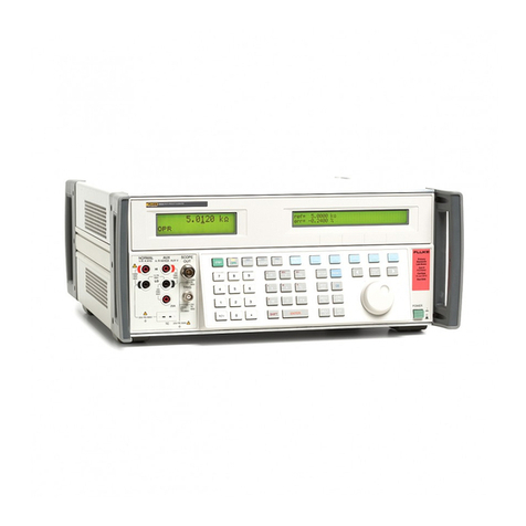
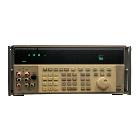
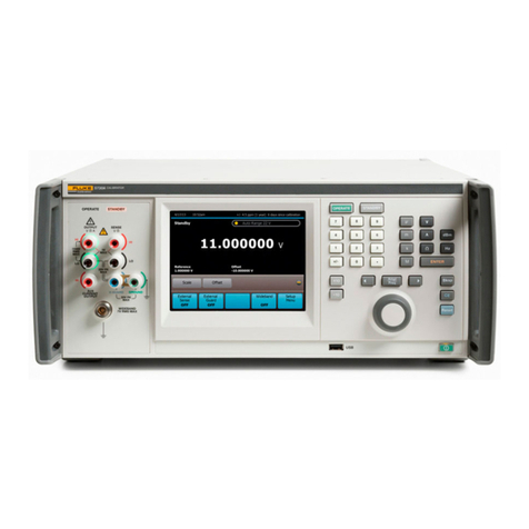
Fluke 5790A User manual

®
5790A
AC Measurement Standard
Operators Manual
PN 893284
January 1992 Rev.4, 1/06
© 1992-2006 Fluke Corporation. All rights reserved. Printed in USA
All product names are trademarks of their respective companies.

LIMITED WARRANTY AND LIMITATION OF LIABILITY
Each Fluke product is warranted to be free from defects in material and workmanship under normal use and
service. The warranty period is one year and begins on the date of shipment. Parts, product repairs, and
services are warranted for 90 days. This warranty extends only to the original buyer or end-user customer of
a Fluke authorized reseller, and does not apply to fuses, disposable batteries, or to any product which, in
Fluke's opinion, has been misused, altered, neglected, contaminated, or damaged by accident or abnormal
conditions of operation or handling. Fluke warrants that software will operate substantially in accordance with
its functional specifications for 90 days and that it has been properly recorded on non-defective media. Fluke
does not warrant that software will be error free or operate without interruption.
Fluke authorized resellers shall extend this warranty on new and unused products to end-user customers
only but have no authority to extend a greater or different warranty on behalf of Fluke. Warranty support is
available only if product is purchased through a Fluke authorized sales outlet or Buyer has paid the
applicable international price. Fluke reserves the right to invoice Buyer for importation costs of
repair/replacement parts when product purchased in one country is submitted for repair in another country.
Fluke's warranty obligation is limited, at Fluke's option, to refund of the purchase price, free of charge repair,
or replacement of a defective product which is returned to a Fluke authorized service center within the
warranty period.
To obtain warranty service, contact your nearest Fluke authorized service center to obtain return
authorization information, then send the product to that service center, with a description of the difficulty,
postage and insurance prepaid (FOB Destination). Fluke assumes no risk for damage in transit. Following
warranty repair, the product will be returned to Buyer, transportation prepaid (FOB Destination). If Fluke
determines that failure was caused by neglect, misuse, contamination, alteration, accident, or abnormal
condition of operation or handling, including overvoltage failures caused by use outside the product’s
specified rating, or normal wear and tear of mechanical components, Fluke will provide an estimate of repair
costs and obtain authorization before commencing the work. Following repair, the product will be returned to
the Buyer transportation prepaid and the Buyer will be billed for the repair and return transportation charges
(FOB Shipping Point).
THIS WARRANTY IS BUYER'S SOLE AND EXCLUSIVE REMEDY AND IS IN LIEU OF ALL OTHER
WARRANTIES, EXPRESS OR IMPLIED, INCLUDING BUT NOT LIMITED TO ANY IMPLIED WARRANTY
OF MERCHANTABILITY OR FITNESS FOR A PARTICULAR PURPOSE. FLUKE SHALL NOT BE LIABLE
FOR ANY SPECIAL, INDIRECT, INCIDENTAL, OR CONSEQUENTIAL DAMAGES OR LOSSES,
INCLUDING LOSS OF DATA, ARISING FROM ANY CAUSE OR THEORY.
Since some countries or states do not allow limitation of the term of an implied warranty, or exclusion or
limitation of incidental or consequential damages, the limitations and exclusions of this warranty may not
apply to every buyer. If any provision of this Warranty is held invalid or unenforceable by a court or other
decision-maker of competent jurisdiction, such holding will not affect the validity or enforceability of any other
provision.
Fluke Corporation
P.O. Box 9090
Everett, WA 98206-9090
U.S.A.
Fluke Europe B.V.
P.O. Box 1186
5602 BD Eindhoven
The Netherlands
11/99
To register your product online, visit register.fluke.com

Declaration of the Manufacturer or Importer
We hereby certify that the Fluke Model 5790A is in compliance with BMPT Vfg 243/1991 and is RFI
suppressed. The marketing and sale of the equipment was reported to the Central Office for
Telecommunication Permits (ZZF). The right to retest this equipment or verify compliance with the
regulation was given to the ZZF.
Bescheinigung des Herstellers/Importeurs
Hiermit wird bescheinigt, daB Fluke Modell 5790A in Übereinstimmung mit den Bestimmungen
der BMPTAmtsblVfg 243/1991 funk-entstört ist. Dem Zentralamt fur Zulassungen im
Femmeldewesen wurde das Inverkehrbringen dieses Gerätes angezeigt und die Berechtigung zur
Überprüfung der Serie auf die Einhaltung der Bestimmungen eingeräumt.
Fluke Corporation
INTERFERENCE INFORMATION
This equipment generates and uses radio frequency energy and if not installed and used in strict
accordance with the manufacturer's instructions, may cause interference to radio and television
reception. It has been type tested and found to comply with the limits for a Class B digital device in
accordance with the specifications of Part 15 of FCC Rules, which are designed to provide
reasonable protection against such interference in a residential installation.
Operation is subject to the following two conditions:
•This device may not cause harmful interference.
•This device must accept any interference received, including interference that may cause
undesired operation.
There is no guarantee the interference will not occur in a particular installation. If this equipment
does cause interference to radio or television reception, which can be determined by turning the
equipment off and on, the user is encouraged to try to correct the interference by one or more of
the following measures:
•Reorient the receiving antenna
•Relocate the equipment with respect to the receiver
•Move the equipment away from the receiver
•Plug the equipment into a different outlet so that the computer and receive are on different
branch circuits
If necessary, the user should consult the dealer or an experienced radio/television technician for
additional suggestions. The user may find the following booklet prepared by the Federal
Communications Commission helpful: How to Identify and Resolve Radio-TV Interference
Problems. This booklet is available from the U.S. Government Printing Office, Washington, DC
20402. Stock No. 004-000-00345-4.


SAFETY TERMS IN THIS MANUAL
This instrument has been designed and tested in accordance with IEC publication
1010-1 (1992-1), Safety Requirements for Electrical Measuring, Control and Laboratory
Equipment, and ANSI/ISA-S82.01-1994, and CAN/CSA-C22.2 No. 1010.1-92. This User
Manual contains information, warning, and cautions that must be followed to ensure safe
operation and to maintain the instrument in a safe condition. Use of this equipment in a
manner not specified herein may impair the protection provided by the equipment.
This instrument is designed for IEC 1010-1 Installation Category II use. It is not designed
for connection to circuits rated over 4800 VA.
WARNING statements identify conditions or practices that could result in personal injury
or loss of life.
CAUTION statements identify conditions or practices that could result in damage to
equipment.
SYMBOLS MARKED ON EQUIPMENT
WARNING Risk of electric shock. Refer to the manual (see the Index for
references).
GROUND Ground terminal to chassis (earth).
Attention Refer to the manual (see the Index for references). This
symbol indicates that information about usage of a feature is contained in
the manual.
AC POWER SOURCE
The instrument is intended to operate from an ac power source that will not apply more
than 264V ac rms between the supply conductors or between either supply conductor
and ground. A protective ground connection by way of the grounding conductor in the
power cord is required for safe operation.
USE THE PROPER FUSE
To avoid fire hazard, for fuse replacement use only the specified unit: 100 or 120 V
operation, 2 ampere/250 volt time delay; 200 or 240 V operation, 1 ampere/250 volt time
delay.
GROUNDING THE INSTRUMENT
The instrument utilizes controlled overvoltage techniques that require the instrument to
be grounded whenever normal mode or common mode ac voltages or transient voltages
may occur. The enclosure must be grounded through the grounding conductor of the
power cord, or through the rear panel ground binding post.

USE THE PROPER POWER CORD
Use only the power cord and connector appropriate for the voltage and plug
configuration in your country.
Use only a power cord that is in good condition.
Refer power cord and connector changes to qualified service personnel.
DO NOT OPERATE IN EXPLOSIVE ATMOSPHERES
To avoid explosion, do not operate the instrument in an atmosphere of explosive gas.
DO NOT REMOVE COVER DURING OPERATION
To avoid personal injury or death, do not remove the instrument cover without first
removing the power source connected to the rear panel. Do not operate the instrument
without the cover properly installed. Normal calibration is accomplished with the cover
closed. Access procedures and the warnings for such procedures are contained both in
this manual and in the Service Manual. Service procedures are for qualified service
personnel only.
DO NOT ATTEMPT TO OPERATE IF PROTECTION MAY BE IMPAIRED
If the instrument appears damaged or operates abnormally, protection may be impaired.
Do not attempt to operate the instrument under these conditions. Refer all questions of
proper instrument operation to qualified service personnel.

i
Table of Contents
Chapter Title Page
1 Introduction and Specifications......................................................... 1-1
1-1. Introduction........................................................................................... 1-3
1-2. Inside the 5790A .............................................................................. 1-3
1-3. Measurement and Transfer Modes ................................................... 1-3
1-4. An Overview of the Features............................................................ 1-4
1-5. Instruction Manuals .............................................................................. 1-5
1-6. 5790A Operators Manual ................................................................. 1-5
1-7. 5790A Remote Programming Reference Guide............................... 1-5
1-8. 5790A Service Manual ..................................................................... 1-5
1-9. Wideband Module (Option 5790A-03)................................................. 1-5
1-10. Current Shunt Adapters ........................................................................ 1-6
1-11. Warranty and Service Information........................................................ 1-6
1-12. Specifications........................................................................................ 1-6
2 Installation ........................................................................................... 2-1
2-1. Introduction........................................................................................... 2-3
2-2. Unpacking and Inspection .................................................................... 2-3
2-3. Environmental and Input Requirements ............................................... 2-4
2-4. Cooling Considerations......................................................................... 2-4
2-5. Placement and Rack Mounting ............................................................. 2-5
2-6. Accessing the Fuse................................................................................ 2-5
2-7. Selecting Line Voltage.......................................................................... 2-6
2-8. Connecting to Line Power .................................................................... 2-6
3 Features ............................................................................................... 3-1
3-1. Introduction........................................................................................... 3-3
3-2. Front Panel Features ............................................................................. 3-3
3-3. Rear Panel Features .............................................................................. 3-3
4 Front Panel Operation......................................................................... 4-1
4-1. Introduction........................................................................................... 4-3
4-2. Turning on the 5790A........................................................................... 4-3
4-3. Power-Up State................................................................................. 4-3

5790A
Operators Manual
ii
4-4. Warmup Requirements..................................................................... 4-4
4-5. Calibrating DC Zeros ....................................................................... 4-5
4-6. Connecting Sources to the 5790A ........................................................ 4-6
4-7. Test Leads and Connectors............................................................... 4-6
4-8. Coaxial Inputs .............................................................................. 4-6
4-9. Dual Banana Inputs...................................................................... 4-6
4-10. Connecting the Guard and Ground Binding Posts ........................... 4-7
4-11. Guard Theory ............................................................................... 4-8
4-12. Guard Connection ........................................................................ 4-8
4-13. External Guard Connection.......................................................... 4-10
4-14. Operating Instructions for all Modes .................................................... 4-11
4-15. Interpreting the Measurement Display ............................................. 4-11
4-16. Using the Measurement Control Menu ............................................ 4-12
4-17. Digital Filter Mode Softkey ......................................................... 4-13
4-18. Digital Filter Restart Softkey ....................................................... 4-13
4-19. Hi Res Softkey ............................................................................. 4-14
4-20. Selecting Auto or Locked Range...................................................... 4-14
4-21. Selecting Continuous or External (Single) Trigger .......................... 4-15
4-22. Instructions for Measurement Mode..................................................... 4-15
4-23. Instructions for Transfer Mode ............................................................. 4-16
4-24. Measuring Frequency Flatness with the Wideband Option.............. 4-16
4-25. Using the Shunt Input for Relative Current...................................... 4-17
4-26. Choosing Delta Units ....................................................................... 4-19
4-27. Establishing a Reference .................................................................. 4-19
4-28. Using the Top-Level Menu Keys.......................................................... 4-21
4-29. [VIEW REF] Key ............................................................................. 4-21
4-30. [UTIL MENUS] Key........................................................................ 4-22
4-31. Checking Instrument Configuration ................................................. 4-23
4-32. Setup Menu....................................................................................... 4-24
4-33. Format Eeprom Menu .................................................................. 4-25
4-34. Setting the Internal Clock............................................................. 4-26
4-35. [SPEC] Key ...................................................................................... 4-27
4-36. Techniques for Reducing Transfer Errors............................................. 4-27
4-37. DC Reversal...................................................................................... 4-27
4-38. Loading............................................................................................. 4-28
4-39. Mechanical Contact .......................................................................... 4-28
4-40. Thermal EMFs.................................................................................. 4-28
4-41. EMI................................................................................................... 4-28
5 Remote Operation ............................................................................... 5-1
5-1. Introduction........................................................................................... 5-3
5-2. Using the IEEE-488 Interface for Remote Control............................... 5-3
5-3. IEEE-488 Bus Restrictions............................................................... 5-3
5-4. IEEE-488 Bus Setup Procedure........................................................ 5-3
5-5. Using the Rs-232 Interface for Remote Control ................................... 5-4
5-6. Serial Remote Control Setup Procedure........................................... 5-4
5-7. Exceptions for Serial Remote Control.............................................. 5-6
5-8. Changing between Remote and Local Operation ................................. 5-6
5-9. Local State........................................................................................ 5-6
5-10. Local with Lockout State.................................................................. 5-6
5-11. Remote State..................................................................................... 5-7
5-12. Remote with Lockout State .............................................................. 5-7
5-13. Command Syntax Information.............................................................. 5-8
5-14. Parameter Syntax Rules.................................................................... 5-8
Contents (continued)
iii
5-15. Extra Space or Tab Characters ......................................................... 5-9
5-16. Terminators....................................................................................... 5-9
5-17. Incoming Character Processing........................................................ 5-10
5-18. Response Message Syntax................................................................ 5-10
5-19. Input Buffer Operation.......................................................................... 5-10
5-20. Using Commands.................................................................................. 5-12
5-21. Multiple Commands ......................................................................... 5-13
5-22. Sequential and Overlapped Commands............................................ 5-13
5-23. Commands that require the CALIBRATION STORE or MODE
Switch to be Enabled ....................................................................... 5-13
5-24. Long-Term Commands..................................................................... 5-13
5-25. Checking 5790A Status ........................................................................ 5-14
5-26. Serial Poll Status Byte (STB) ........................................................... 5-14
5-27. Service Request Line (SRQ) ........................................................ 5-14
5-28. Service Request Enable Register (SRE)....................................... 5-14
5-29. Programming the STB and SRE .................................................. 5-15
5-30. Event Status Register (ESR)............................................................. 5-17
5-31. Event Status Enable Register (ESE) ............................................ 5-17
5-32. Bit assignments for the ESR and ESE.......................................... 5-17
5-33. Programming the ESR and ESE................................................... 5-17
5-34. Instrument Status Register (ISR)...................................................... 5-19
5-35. Instrument Status Change Registers............................................. 5-19
5-36. Instrument Status Change Enable Registers................................. 5-19
5-37. Bit Assignments for the ISR, ISCR, and ISCE ............................ 5-19
5-38. Programming the ISR, ISCR, and ISCE ...................................... 5-20
5-39. Output Queue ................................................................................... 5-20
5-40. Error Queue ...................................................................................... 5-20
5-41. IEEE-488 Interface Configuration........................................................ 5-21
5-42. Bus Communication Overview............................................................. 5-22
5-43. Device-Dependent Commands ......................................................... 5-22
5-44. Common Commands ........................................................................ 5-22
5-45. Interface Messages ........................................................................... 5-22
5-46. Definition: Queries and Commands ................................................. 5-23
5-47. Functional Elements of Commands.................................................. 5-23
5-48. Interface Messages ........................................................................... 5-23
5-49. Remote Program Examples................................................................... 5-23
5-50. Writing an SRQ and Error Handler .................................................. 5-24
5-51. Taking a Measurement ..................................................................... 5-24
5-52. Efficiently Taking N Successive Readings ...................................... 5-25
5-53. Locking the 5790A Range................................................................ 5-25
5-54. Calibrating the 5790A Remotely...................................................... 5-25
5-55. The IEEE-488 Connector...................................................................... 5-27
6 Remote Commands............................................................................. 6-1
6-1. Introduction........................................................................................... 6-3
6-2. Alphabetical List of IEEE-488.2 Common Commands........................ 6-7
6-3. Alphabetical List of 5790A Device-Dependent Commands................. 6-13
7 Using the RS-232 Interface................................................................. 7-1
7-1. Introduction........................................................................................... 7-3
7-2. Serial Interface Specifications .............................................................. 7-3
7-3. Setting Up and Connecting the Serial Interface.................................... 7-4
7-4. Printing Calibration Reports ................................................................. 7-5
7-5. Sample Measurement Shifts Report ................................................. 7-6

5790A
Operators Manual
iv
7-6. Sample Calibration Constants Report............................................... 7-12
8 Operator Maintenance......................................................................... 8-1
8-1. Introduction........................................................................................... 8-3
8-2. Accessing the Fuse................................................................................ 8-3
8-3. Cleaning the Air Filter .......................................................................... 8-4
8-4. General Cleaning .................................................................................. 8-4
8-5. Calibration ............................................................................................ 8-5
9 Options and Accessories ................................................................... 9-1
9-1. Introduction........................................................................................... 9-3
9-2. Wideband Module (Option 5790A-03)................................................. 9-3
9-3. Accessories ........................................................................................... 9-3
9-4. Fluke A40 and A40A Current Shunt Adapter (5790A-7001) .......... 9-3
9-5. Fluke A40A Current Shunt Adapter for Input 1 (792A-7004)......... 9-3
9-6. Low Thermal EMF Test Leads (5440A-7002)................................. 9-4
9-7. Rack Mount Kit (Y5737).................................................................. 9-4
9-8. Shielded IEEE-488 Interface Cables (Y8021, Y8022, and Y8023) . 9-4
9-9. RS-232-C Null-Modem Cables (Y1702 and Y1703) ....................... 9-4
Appendices
A Glossary of AC-DC Transfer Related Terms .............................................. A-1
B ASCII and IEEE-488 Bus Codes................................................................. B-1
C Calibration Constant Information................................................................ C-1
D 5790A Error Codes...................................................................................... D-1
E 5200A Verification and Calibration ............................................................ E-1

v
List of Tables
Table Title Page
2-1. Standard Equipment ............................................................................................... 2-3
2-2. Line Power Cord Types Available from Fluke ...................................................... 2-3
3-1. Front Panel Features............................................................................................... 3-4
4-1. Power-Up State Defaults and Volatility................................................................. 4-4
4-2. Nonvolatile Setup Parameter Factory Defaults ...................................................... 4-5
4-3. Input Test Lead Summary...................................................................................... 4-7
4-4. Input Impedance Summary .................................................................................... 4-7
4-5. Measurement Display Amplitude Resolution ........................................................ 4-11
4-6. Measurement Display Frequency Resolution......................................................... 4-11
5-1. Operating State Transitions.................................................................................... 5-8
5-2. Units Accepted in Parameters and Used in Responses .......................................... 5-9
5-3. Response Data Types ............................................................................................. 5-11
5-4. Status Register Summary ....................................................................................... 5-17
5-5. IEEE-488 Interface Function Subsets Supported................................................... 5-22
5-6. Functional Elements of Commands ....................................................................... 5-27
5-7. Interface Messages that the 5790A Accepts........................................................... 5-28
5-8. Interface Messages that the 5790A Sends.............................................................. 5-29
6-1. Command Summary by Function .......................................................................... 6-3
7-1. Serial Interface Parameter Choices ........................................................................ 7-4
9-1. Accessories............................................................................................................. 9-3

5790A
Operators Manual
vi

vii
List of Figures
Figure Title Page
1-1. Dimensions............................................................................................................. 1-7
2-1. Line Power Cord Types Available from Fluke ...................................................... 2-4
2-2. Accessing the Fuse................................................................................................. 2-5
2-3. Line Power Label and Switch Location ................................................................. 2-7
3-1. Accessing the Fuse................................................................................................. 3-3
4-1. Recommended Test Lead Connections to Test a Voltmeter .................................. 4-9
4-2. Recommended Test Lead Connections to Test a Source ....................................... 4-10
5-1. Status Register Overview ....................................................................................... 5-16
5-2. Status Byte and SRE Bit Definitions...................................................................... 5-18
5-3. Bit Assignments for ESE and ESE......................................................................... 5-19
5-4. Bit Assignments for the ISR, ISCEs and ISCRs .................................................... 5-21
5-5. IEEE-488 connector pinout (Rear Panel View) ..................................................... 5-30
7-1. RS-232 Connector Pinout ...................................................................................... 7-3
8-1. Accessing the Fuse................................................................................................. 8-3
8-2. Accessing the Air Filter.......................................................................................... 8-4

5790A
Operators Manual
viii

1-1
Chapter 1
Introduction and Specifications
Title Page
1-1. Introduction........................................................................................... 1-3
1-2. Inside the 5790A .............................................................................. 1-3
1-3. Measurement and Transfer Modes ................................................... 1-3
1-4. An Overview of the Features............................................................ 1-4
1-5. Instruction Manuals .............................................................................. 1-5
1-6. 5790A Operators Manual ................................................................. 1-5
1-7. 5790A Remote Programming Reference Guide............................... 1-5
1-8. 5790A Service Manual ..................................................................... 1-5
1-9. Wideband Module (Option 5790A-03)................................................. 1-5
1-10. Current Shunt Adapters ........................................................................ 1-6
1-11. Warranty and Service Information........................................................ 1-6
1-12. Specifications........................................................................................ 1-6

5790A
Operators Manual
1-2

Introduction and Specifications
Introduction 1
1-3
1-1. Introduction
The 5790A AC Measurement Standard is a systems instrument that measures ac voltage
with the uncertainty of a thermal transfer standard. You control the 5790A's operation
from the front panel or remotely over the serial or IEEE-488 interface.
You can operate the 5790A in measurement mode or transfer mode. In measurement
mode, the 5790A operates as a digital ac voltmeter with up to 8 digits of resolution.
Measurement mode uses an internal dc reference. In transfer mode, you apply an external
dc or ac reference source. The 5790A automatically performs switching and calculations,
and displays the resulting ac-dc or ac-ac difference on the vacuum fluorescent Control
Display.
The 5790A covers a voltage range of 700 µV to 1000 V (70 mV minimum in transfer
mode), and a frequency range of 10 Hz to 1 MHz. A wideband voltage option extends
frequency range to 30 MHz. The 5790A is also compatible with Fluke A40 current
shunts, which permit you to make ac-dc or ac-ac current transfer measurements up to
20 A. Refer to the Specifications for details.
A variety of input connections allows you to use the one that best suits your application.
There are four sets of input terminals on the 5790A, two 50ΩType "N" connectors and
two sets of five-way binding posts. One 50ΩType "N" and one set of binding posts is
dedicated to the ac measurement and transfer modes. AC or DC voltages can be applied
to either input connection, allowing you to perform automated ac-dc transfer
measurements. The second Type "N" input connection supports the optional wideband
mode, and the SHUNT binding posts are for Fluke A40 Series current shunts.
1-2. Inside the 5790A
Two patented internal standards contribute the most to the 5790A's ability to measure rms
ac voltage with such low uncertainty. These two standards are a stable and precisely
variable dc source similar to the one in the Fluke 5700A Calibrator and a high-
performance thermal rms sensor similar to the one in the Fluke 792A AC/DC Transfer
Standard.
Reference amplifiers establish the accuracy and stability of the internal dc source. A
patented 26-bit digital-to-analog converter (dac) provides the 5790A with the ability to
precisely vary its internal dc source. This is a pulse-width modulated dac with linearity
typically better than 0.2 ppm of full scale.
On the ac side, the Fluke rms sensor is similar in principle to a thermal voltage converter
(thermocouple), but has faster settling time, low dc reversal error, higher signal-to-noise
ratio, and excellent frequency performance.
1-3. Measurement and Transfer Modes
With the 5790A you can measure an ac or dc voltage just as you would with a voltmeter
(measurement mode), or you can connect an external dc standard for comparison to an
applied ac voltage as you would do with an ac-dc transfer standard (transfer mode).
When in measurement mode, among many other things the 5790A automatically does the
following:
1. Compares the heating effect of the incoming signal to that of the 5790A internal dc
source, through the Fluke rms sensor. This results in direct detection of true rms
value.
2. Adjusts its internal dc source for a null at the output of the rms sensor, in the process
eliminating many sources of error.

5790A
Operators Manual
1-4
3. Applies correction factors saved at time of calibration.
4. Presents the results of the ac-dc transfer on the Measurement Display, showing rms
amplitude and frequency of the signal being applied, accurate to within the
uncertainty of the internal dc standard combined with the transfer uncertainty. (See
the Specifications.)
Pressing a softkey (a key whose function is defined on the Control Display) sets an
incoming signal as a reference, activating transfer mode. In transfer mode, the 5790A
automatically does the following:
1. Displays the reference source, the formula it is using to compute ac-dc or ac-ac
difference, and the results of the formula.
2. Provides you with a softkey to easily correct for dc reversal error. You apply both
polarities of dc and the 5790A computes the average of the absolute values of the
applied dc.
3. Continuously shows the results of comparisons of the heating effect of the incoming
signal to that of the stored reference.
4. Applies correction factors saved at time of calibration as necessary.
5. Presents the results of the transfer on the Control Display, accurate to within the
uncertainty of the transfer device. (See the Specifications.)
6. Always displays the measured amplitude and frequency of the input signal on the
Measurement Display, no matter what other processes are taking place.
1-4. An Overview of the Features
See Section 3 for detailed descriptions of front panel connectors, controls, and displays.
Features of the 5790A include the following:
•Two main input choices: 50ΩType "N" coaxial or five-way binding posts
•A dedicated SHUNT input terminal that provides current transfer capability.
•WIDEBAND 50ΩType "N" coaxial connector for measuring signals up to 30 MHz.
(Requires Option 5790A-03 Wideband Module.)
•Closed-case periodic calibration in which no physical adjustments are necessary.
•The ability to print or upload calibration reports. For reporting purposes, the 5790A
maintains in nonvolatile memory a database of the calibration shifts from the
previous calibration as well as from the most recent calibration. Calibration reports
provide a way to develop a performance history of each 5790A.
•Real-time clock for date and time stamping reports, recording the time and date of
calibration, and calculating specifications.
•Standard IEEE-488 (GPIB) interface, complying with ANSI/IEEE Standards 488.1-
1987 and 488.2-1987.
•EIA Standard RS-232-C serial data interface for printing, displaying, or transferring
internally stored calibration constants, and for remote control of the 5790A.
•Extensive internal software-controlled self testing and diagnostics of analog and
digital functions.

Introduction and Specifications
Instruction Manuals 1
1-5
1-5. Instruction Manuals
This Operators Manual contains operating instructions for the 5790A. The 5790A
Manual Set provides complete information for the Operators and service or maintenance
personnel. The set includes the following manuals:
•5790A Operators Manual, pn 893284
•5790A Remote Programming Reference Guide, pn 893375
•5790A Service Manual, pn 893292
1-6. 5790A Operators Manual
This 5790A Operators Manual provides complete information for installing the 5790A
and operating it from the front panel and from the remote interface. The manual also
provides a glossary of terms related to ac-dc transfers as well as other information for the
Operators and programmer, such as specifications, operating parameter setup procedures,
and remote programming examples.
1-7. 5790A Remote Programming Reference Guide
The 5790A Remote Programming Reference Guide contains a summary of remote
commands for the 5790A. It also contains information needed to determine system status
using the status byte and registers.
1-8. 5790A Service Manual
The 5790A Service Manual is a maintenance guide for the 5790A. The following topics
are included in the 5790A Service Manual:
Theory of operation
•Performance testing
•Maintenance
•Calibration
•Troubleshooting
•Parts lists
•Schematics
1-9. Wideband Module (Option 5790A-03)
To measure ac voltage in the 1 to 30 MHz range, the 5790A requires the 5790A-03
Wideband Module. Instructions for operating the 5790A in wideband mode are provided
in Section 4, and specifications for wideband operation are provided at the end of this
section.
The WIDEBAND input presents a 50Ωload to the source. Signals accepted are from
700 µV to 7 V over a frequency range of 10 Hz to 30 MHz. Only the lower eight 5790A
voltage ranges are used by the WIDEBAND input.
Use the WIDEBAND input to measure the frequency flatness of 50Ωsignal sources such
as the 5700A WIDEBAND output. You can use the delta display to show the error of the
source in ppm as you sweep the source through the WIDEBAND input frequency range.

5790A
Operators Manual
1-6
1-10. Current Shunt Adapters
Accessory 5790A-7001 allows you to connect Fluke A40 or A40A Current Shunts the
5790A SHUNT input for making current transfers up to 20 A. Accessory 792A-7004
allows you to connect Fluke A40 Current Shunts to the INPUT 1 Type "N" connector for
making current transfers up to 5 A.
1-11. Warranty and Service Information
Each 5790A is warranted for a period of 1 year on delivery to the original purchaser. The
warranty is printed on the reverse side of the title page of this manual.
Factory authorized service for the 5790A is available at selected Technical Service
Centers. For warranty or after-warranty service, contact the nearest Technical Service
Center for instructions. A complete list of Technical Service Centers is provided in
Appendix D.
To reship the 5790A, use its original shipping carton. If the original carton is not
available, use a container that provides adequate protection during shipment. Protect the
5790A with at least three inches of shock-absorbing material on all sides of the container.
Do not use loose fill to pad the shipping container. Loose fill allows the instrument to
settle to one corner of the shipping container, which could result in damage during
shipment.
1-12. Specifications
Specifications are valid after allowing a warm-up period of 30 minutes, or twice the time
the 5790A has been turned off, whichever is less. For example, if the 5790A has been
turned off for 5 minutes, the warm-up period is 10 minutes. To simplify evaluation of
how the 5790A covers you workload, use the Absolute Uncertainty Specification. Those
include stability, temperature coefficient, linearity, and traceability to external standards.
Note
When you use the 5790A within ±5 °C of the temperature of the last
calibration, you do not need to add anything to the Absolute Uncertainty
Specifications to determine the ratios between 5790A uncertainties and the
uncertainties of a unit under test. The initial calibration at Fluke is done at
23 °C. (You can verify the temperature of the last calibration at any time by
pressing the [SPEC] key.)
Use the Relative Uncertainty Specifications if you use a different procedure to calibrate
the 5790A than is specified in the 5790A Service Manual. To calculate absolute
uncertainty specifications under such conditions, combine the absolute uncertainty
associated with your external equipment and calibration procedures with the Relative
Uncertainty Specifications. Secondary Performance and Operating Characteristics are
provided for special calibration requirements such as stability or operation at temperature
extremes.
Other manuals for 5790A
1
Table of contents
Other Fluke Test Equipment manuals

Fluke
Fluke 2700G Use and care manual

Fluke
Fluke 190 Series II User manual

Fluke
Fluke ScopeMeter 190B Series User manual

Fluke
Fluke 714 User manual

Fluke
Fluke IT100 IntelliTone Toner User manual

Fluke
Fluke 725Ex Use and care manual

Fluke
Fluke 729 Pro User manual

Fluke
Fluke 5320A Parts list manual

Fluke
Fluke 717 1G User manual

Fluke
Fluke 1662 User manual

Fluke
Fluke CableAnalyzer DSX-500 User manual

Fluke
Fluke RUSKA 7252 User manual

Fluke
Fluke DTX-PC S Series User manual

Fluke
Fluke DTX-PCU6S User manual

Fluke
Fluke 5730A User manual

Fluke
Fluke TS 44 PRO Parts list manual

Fluke
Fluke TS 120 User manual

Fluke
Fluke T50 User manual

Fluke
Fluke P3100 Series User manual

Fluke
Fluke 714 User manual