FLUVO 27222-C User manual
Side channel blower
Operator’s Manual
Translation of the Original
27222-C
GB

SchmalenbergerGmbH+Co.KG
D-72072 Tübingen / Germany
SKV
Version: 27222 - C
2

EG-Konformitätserklärung
Déclaration de conformité CE / EC declaration of conformity /
Declaración CE de conformidad / Dichiarazione CE di conformità
Hersteller / Fabricant / Manufacturer / Fabricante / Produttore
Schmalenberger GmbH+Co KG
Flow technology
Im Schelmen 9-11
D-72072 Tübingen / Germany
Produkt / Produit / Product / Producto / Prodotto
Seitenkanalverdichter / Soufflante à canal latéral / Side channel blower / Soplador de canal lateral /
Compressore a canale laterale
Typ / Modèle / Model / Modelo / Tipo
SKV 45 / SKV 105 / SKV 135 / SKV 255 / SKV 360 / SKV 600
Hiermit erklären wir, dass die spezifische Bauart in Übereinstimmung mit den folgenden Richtlinien hergestellt worden ist:
Par la présente, nous declarons, que le type de est produit conforme aux dispositions des directives européenne sci après:
We hereby declare that the specific type has been produced in accordance with the following standards:
Por la presente les confirmamos que lo abajo especificado ha sido fabrico en conformidad con las siguientes normas:
Si dichiara che il modello della costruzione specifica è stato realizzato in conformità alle sequenti norme:
EG-Richtlinien / Directives de la CE / EC Directives / Normativas de la CE / Direttive CE
• 2006/42/EC
• 2006/95/EC
• 2004/108/EC
Zur sachgerechten Umsetzung der in der EG-Richtlinie genannten Sicherheits- und Gesundheitsanforderungen wurde(n)
folgende Norm(en) herangezogen:
Pour mettre en partique dans les règles de l'art les prescritions en matière de sécurité et de santé stipulées dans les Directives
de la CE, il a été tenu compte de la /des norme(s):
For the relevant implementation of the safety and health requirements mentioned in the Directives, the following standard(s)
must be required:
Con el fin de realizar de forma adecuada las exigencias referentes a la seguridad y a la snidad mencionadas en las
normativas de la CE fuè(ron) consultada(s) la(s) siguiente(s) normativa(s):
Per la verifica della Conformità di cui alle Direttive sopra menzionate, sono state consultate le seguenti, norme Armonizzate
EN:
Harmonisierte Normen / Normes harmonisées / Harmonised Standards / Normas armonizadas / Norme armonizzate
EN ISO 12100-1, EN ISO 12100-2, EN 61000-6-2, EN 61000-6-3, EN 809, EN ISO 14121-1
Tübingen, December 21, 2009
-------------------------------------------------------------------------------------------------
Leiter Qualitätssicherung / Directeur d’assurance de la qualité /
Manager of quality assurance / Director del aseguramiento de calidad /
Direzione assicurazione qualità / Tel. +49(0)7071 7008-18
3
SKV
Version: 27222 - C Schmalenberger GmbH + Co. KG
D-72072 Tübingen / Germany

TABLE OF CONTENTS
4
Side channel blower
Version: 27222-C
Schmalenberger GmbH + Co. KG
D-72072 Tübingen / Germany
Table of Contents
1 General information.......................................................................... 6
1.1 User information.............................................................................................................. 6
1.2 Proper use ...................................................................................................................... 8
1.3 Other applicable documents ........................................................................................... 8
1.4 Technical data / specification.......................................................................................... 9
2 Safety instructions.......................................................................... 10
2.1 General information ...................................................................................................... 10
2.2 Signs and symbols........................................................................................................ 10
2.3 Responsibilities of the operator..................................................................................... 11
2.4 Safety instructions for installation ................................................................................. 11
2.5 Safety instructions for connection................................................................................. 11
2.6 Safety instructions for commissioning........................................................................... 12
2.7 Safety instructions for operation ................................................................................... 12
2.7.1 Suction effect ................................................................................................................. 12
2.7.2 Blowing effect................................................................................................................. 12
2.7.3 Temperature .................................................................................................................. 12
2.8 Safety instructions for maintenance and repair work.................................................... 13
2.9 Potential sources of danger from the side channel blower........................................... 13
3 Transport, storage and assembly.................................................. 15
3.1 Transport and storage................................................................................................... 15
3.1.1 Transport........................................................................................................................ 15
3.1.2 Storage .......................................................................................................................... 16
3.1.3 Preservation................................................................................................................... 16
3.2 Unpacking, cleaning and assembly .............................................................................. 17
3.2.1 Unpacking...................................................................................................................... 17
3.2.2 Cleaning......................................................................................................................... 17
3.2.3 Assembly ....................................................................................................................... 17
3.3 Setting up and connecting ............................................................................................ 17
3.3.1 Before starting to set up, check the following ................................................................ 18
3.3.2 Installation and set-up of the side channel blower......................................................... 19
3.3.3 Connecting the pipelines................................................................................................ 19
3.3.4 Electrical connection - general....................................................................................... 20
3.3.5 Electrical connection - three-phase current ................................................................... 22
4 Operation of the side channel blower........................................... 24
4.1 Initial commissioning .................................................................................................... 24
4.1.1 Start the side channel blower......................................................................................... 24
5 Operation......................................................................................... 24
5.1 Operation monitoring .................................................................................................... 24
5.1.1 Piping diagram ............................................................................................................. 25
5.1.2 Blower accessories ..................................................................................................... 26
6 Notices of incorrect operation....................................................... 27
6.1 General information ...................................................................................................... 27

TABLE OF CONTENTS
5
Side channel blower
Version: 27222-C
Schmalenberger GmbH + Co. KG
D-72072 Tübingen / Germany
6.1.1 Faults............................................................................................................................. 27
6.2 Shutdown...................................................................................................................... 27
7 Maintenance / repair........................................................................ 28
7.1 General information...................................................................................................... 28
7.2 Maintenance / inspection.............................................................................................. 28
7.2.1 Checks........................................................................................................................... 28
7.2.2 Lubrication and change of lubricant............................................................................... 29
7.3 Repair........................................................................................................................... 29
7.3.1 General information....................................................................................................... 29
7.3.2 Preparations for disassembly ........................................................................................ 29
7.3.3 Disassembly / removal of the side channel blower........................................................ 29
7.3.4 Disassembly / dismantling the side channel blower ...................................................... 30
8 Spare parts list / drawing................................................................ 31
9 Appendix.......................................................................................... 34
9.1 Decommissioning / placing in storage / preservation ................................................... 34
9.1.1 Placing new side channel blowers in storage................................................................ 34
9.1.2 Recommissioning after being placed in storage............................................................ 34
9.2 Disposal........................................................................................................................ 35
9.3 Documents for operation .............................................................................................. 35
9.4 Dimension sheet........................................................................................................... 36
9.5 Ordering spare parts..................................................................................................... 38

OPERATING INSTRUCTIONS
6
Side channel blower
Version: 27222 - C
Schmalenberger GmbH + Co. KG
D-72072 Tübingen / Germany
1 General information
1.1 User information
This Operator's Manual will make it easier for you to become familiar with the side channel
blower and make full use of its range of options.
The Operator’s Manual contains important information to ensure the side channel blower
is operated safely, properly and economically. Observing the instructions helps to avoid
dangers, avoid repair costs and downtimes, and increase the reliability and service life of
the side channel blower.
The Operator's Manual does not take into consideration requirements for specific location.
The operator is responsible for observing these requirements.
The nameplate indicates the series and frame size, the most important operating data and
the factory number. Please specify this information if you have questions, a subsequent
order, or especially when ordering spare parts.
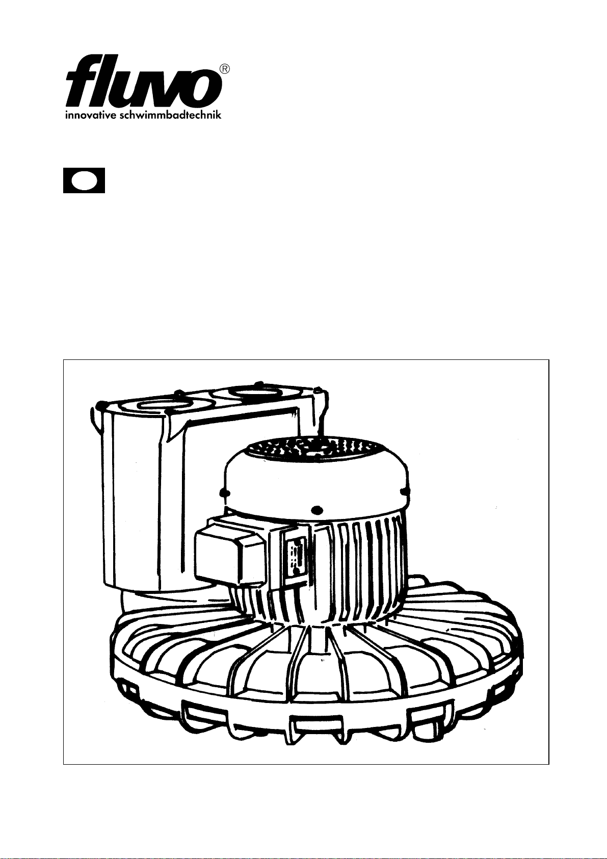
Fig. 1: Side channel blower
S1 Blower housing
S2 Drive motor
S3 Pressure connection
S4 Suction connection
S5 Sound absorber housing
S6 Terminal box

OPERATING INSTRUCTIONS
7
Side channel blower
Version: 27222 - C
Schmalenberger GmbH + Co. KG
D-72072 Tübingen / Germany
Fig. 2: Blower nameplate
1 Blower type 6 Order number
2 Flow rate 7 Medium temperature
3 Operating voltage 8 Power output
4 Frequency / protection type 9 Delivery pressure
5 Item number
The blower nameplate (Fig. 2/ shows an example) is located on the fan hood of the blower.
Fig. 3: Motor nameplate
1 Blower type 4 Frequency / speed
2 Motor protection type /heat class5 Voltage / current
3 Power output/
Power factor
The motor nameplate (Fig. 3 / shows an example) is located on the electric motor.
1
2
3
4
5
6
7
8
9
1
2
3
4
5
10,0 / 5,8
10,0 / 5,8

OPERATING INSTRUCTIONS
8
Side channel blower
Version: 27222 - C
Schmalenberger GmbH + Co. KG
D-72072 Tübingen / Germany
1.2 Proper use
The side channel blower is intended exclusively for conveying clean air and must only be
used in accordance with the original specification. It must only be operated with the values
defined in this Technical Documentation regarding conveying medium, flow rate, speed,
density, pressure, temperature, motor power or other data defined in the specification. Any
other or more extensive use is considered improper use. The manufacturer shall not be
liable for any resulting damage.
The permissible conveying medium temperature for the standard design is -30° to +40°C.
Solids or other impurities contained in the conveying medium must be filtered out before
the medium enters the side channel blower.
The maximum ambient temperature must not exceed +40°C. The minimum ambient
temperature must be at least -20°C.
The side channel blower isnot suitable for setting up ina potentially explosive atmosphere.
If the side channel blower will be used for any purpose other than what is prescribed in the
specification, always consult with the manufacturer. We will be pleased to determine what
adjustments would be required for the new intended use.
Conversions and changes to the side channel blower are not permitted!
Proper use also includes observing the Operator's Manual.
1.3 Other applicable documents
Each side channel blower has various documents which belong together with the
Technical Documentation for the side channel blower. They are:
• The Operator's Manual for the side channel blower
• The Operator's Manual for the drive
• The Operator's Manual for the accessories listed in the specification
• Acceptance reports from TÜV, etc.
• Test run report
• Performance run report
• Assembly drawing (dimension sheet)
• Test certificate for (ex) design
• Declaration of Conformity
• Specification with all information
Not all the documents named above exist or are included in every case. Observe the
information in the specification in this regard.

OPERATING INSTRUCTIONS
9
Side channel blower
Version: 27222 - C
Schmalenberger GmbH + Co. KG
D-72072 Tübingen / Germany
1.4 Technical data / specification
• The system meets the requirements of the VDE regulations.
• The electric motor corresponds to protection type IP 54.
• The side channel blower as a whole meets the requirements of protection class 1.
The specification of the delivered side channel blower is the most important document for
every Operator's Manual. It contains a summary of all factual and technical data for the
side channel blower. It is the side channel blower's "birth certificate" and must be treated
as such.
The confirmation of order together with the delivery slip can be used as a replacement for
proof of technical data.
Blower type SKV 45 SKV 105 SKV 135 SKV 255 SKV 360 SKV 600
Output 0.95 kW 1.2 kW 2.3 kW 2.9 kW 5.5 kW 7.0 kW
Voltage 230 / 400 V 230 / 400 V 230 / 400 V 230 / 400 V 400 V 400 V
Frequency 50 Hz 50 Hz 50 Hz 50 Hz 50 Hz 50 Hz
Current 4,0 / 2,3 A 4,35 / 2,5 A 7,4 / 5,6 A 10,0 / 5,8 A 10,2 A 13,4 A
Speed 2730 rpm 2800 rpm 2870 rpm 2860 rpm 2910 rpm 2890 rpm
Delivery 45 m
3
/h 105 m
3
/h 135 m
3
/h 255 m
3
/h 360 m
3
/h 600 m
3
/h
Discharge
pressure 150 mbar 150 mbar 150 mbar 150 mbar 150 mbar 150 mbar
Weight 22,0 kg 22,0 kg 36.0 kg 56,0 kg 88.0 kg 107.0 kg

OPERATING INSTRUCTIONS
10
Side channel blower
Version: 27222 - C
Schmalenberger GmbH + Co. KG
D-72072 Tübingen / Germany
2 Safety instructions
2.1 General information
• Make certain before commissioning that the operating personnel have read and
understood the Operator's Manual. It is the owner rather than the operator who
is responsible for safety!
• Make certain the safety requirements and laws for the use of side channel blowers
which apply to the operating company and/or country in which the system is operated
are observed.
• Use the side channel blower only when it is in flawless condition technically and only
according to its intended purpose. Be conscious of safety and dangers and observe all
the instructions of this Operator’s Manual!
Eliminate all malfunctions that could have a detrimental effect on safety immediately.
2.2 Signs and symbols
We warn you of sources of danger in this Operator's Manual through corresponding
notices. The use of symbols is designed to direct your attention at these notices.
Notices placed directly on the side channel blower, such as the arrow for direction of
rotation and identification of fluid connections, must always be observed and must be
maintained in legible condition.
Caution - risk of injury!
This symbol warns you of dangers due to mechanical effects.
Caution - danger of death!
This symbol warns you of dangers due to electrical current.
Note!
This symbol warns you of actions that may damage or destroy the side channel
blower. It provides information about financially efficient use of the side
channel blower.

OPERATING INSTRUCTIONS
11
Side channel blower
Version: 27222 - C
Schmalenberger GmbH + Co. KG
D-72072 Tübingen / Germany
2.3 Responsibilities of the operator
• The side channel blower is built according to the state of the art and recognised safety
engineering rules. Nevertheless, danger to life and limb of the operator or third parties,
or damage to other property may arise during use.
• The owner / operator must therefore take care to heed the safety instructions in this
Operator's Manual.
2.4 Safety instructions for installation
• The side channel blower is designed for installation in a complete machine or system.
The side channel blower is delivered without a contact safety device. If a contact safety
device is required (for example when conveying gaseous media above 60°C) it must
be provided by the system manufacturer when the side channel blower is installed in
the system.
• If the side channel blower is installed in a shaft, the shaft must have sufficient
ventilation (motor cooling).
2.5 Safety instructions for connection
• Electrical equipment must only be installed and serviced by qualified personnel.
Applicable safety regulations and equipment requirements at the installation site must
be observed. The term qualified professional (Fachkraft) is defined in VDE 0105 and
IEC364. This Operator's Manual does not contain any information for non-qualified
persons. We explicitly draw to your attention that the stipulations of the EC prohibit the
use of non-qualified persons on electrical systems.
• Work on the side channel blower's electrical equipment must only be performed by a
professional electrician or persons instructed by and under the direction and
supervision of an electrician in accordance with electrical regulations.
• Hazards due to electrical energy must be excluded (for specific details, see country-
specific regulations and/or your local energy supply company).
• The information on the nameplate and the conditions for electrical connection must
match.
The side channel blower must only be operated with an FI circuit breaker.
OPERATING INSTRUCTIONS
12
Side channel blower
Version: 27222 - C
Schmalenberger GmbH + Co. KG
D-72072 Tübingen / Germany
2.6 Safety instructions for commissioning
• Before turning on the side channel blower or placing it in operation, make certain no
one can be endangered by the side channel blower starting up!
2.7 Safety instructions for operation
2.7.1 Suction effect
Side channel blowers produce a powerful suction effect
2.7.2 Blowing effect
2.7.3 Temperature
Caution - risk of injury!
• Object including articles of clothing as well as hair can be sucked in at the
suction connection.
• Do not remain near the suction opening during operation.
• The side channel blower must never be operated with the suction opening
open. The open suction opening must be covered with a protective grating
in accordance with DIN EN 294.
• Do not reach into the suction opening.
Caution - risk of injury!
• Very strong blowing effect on the blowing connection. Objects that are
drawn in may be forcibly ejected at high speed.
• The side channel blower is intended exclusively for conveying clean air.
Foreign objects or impurities that are drawn in must be filtered out before
the medium enters the side channel blower.
• The side channel blower must never be operated with an open blowing
connection and must therefore be covered with a protective grating in
accordance with DIN EN 294.
• Do not reach into the blower opening.
Caution - risk of injury!
The blower housing heats up during operation. If the temperature increases
above +50°C, the side channel blower must be protectedagainst direct contact
by the operator.
OPERATING INSTRUCTIONS
13
Side channel blower
Version: 27222 - C
Schmalenberger GmbH + Co. KG
D-72072 Tübingen / Germany
2.8 Safety instructions for maintenance and repair work
• Repairs of any nature must only be made by qualified professionals.
• Before making repairs to the side channel blower, disconnect it from its electrical power
source and prevent it from being turned on again.
2.9 Potential sources of danger from the side channel blower
Side channel blower are built according to the state of the art and recognised safety
engineering rules. Nevertheless, danger to life and limb of the operator or third parties, or
damage to other property may arise during use.
A residual risk still remains!
Potential danger zones of the side channel blower are:
• the suction connection
• the blowing connection
• the blower housing
Danger of entanglement!
A powerful suction effect is present on the suction connection.
Danger of impact!
Objects which have been drawn in may be forcibly ejected at high speed.
Caution - risk of injury!
• Make certain to wear close fitting clothes and keep long hair covered.
Remove jewellery before starting work.
• Do not reach into the suction connection.
• Always operate the side channel blower with a protective grating in
accordance with DIN EN 294!
Caution - risk of injury!
• Position a filter upstream from the side channel blower to filter out objects
that have been drawn in.
• Always operate the side channel blower with a protective grating in
accordance with DIN EN 294!
OPERATING INSTRUCTIONS
14
Side channel blower
Version: 27222 - C
Schmalenberger GmbH + Co. KG
D-72072 Tübingen / Germany
Danger of burns!
The blower housing heats up during operation and must therefore be protected against
direct access.
Electrical equipment
Caution - risk of injury!
Protect the user from contact with the side channel blower!
Install a guard to prevent contact.
Allow the side channel blower to cool off before starting maintenance and
repair work.
Caution! Electrical voltage!
Work on the side channel blower must only be performed by properly trained
and qualified professionals and must be performed in accordance with
electrical rules.

OPERATING INSTRUCTIONS
15
Side channel blower
Version: 27222 - C
Schmalenberger GmbH + Co. KG
D-72072 Tübingen / Germany
3 Transport, storage and assembly
3.1 Transport and storage
3.1.1 Transport
Fig. 4: T1 Side channel blower
T2 Crate
T3 Conveyor belt
T4 Pallet
Side channel blowers (T1) must be transported lying down!
The side channel blower (T1) is secured on a pallet (T4) with bands (T3) for transport. For
transport over extended distances it is packed in cases or crates (T2).
Note!
The lifting lugs on the motor are only designed for the weight of the motor
alone. A unit consisting of a motor and side channel blower must be attached
on both the motor and side channel sides. If necessary, the position of the
centre of gravity is identified on the side channel blower unit itself and the
positions for inserting lifting equipment are marked on the packaging.
Caution - risk of injury!
Use only suitable lifting equipment and load holding devices which are in
perfect working order and have adequate load-bearing capacity!

OPERATING INSTRUCTIONS
16
Side channel blower
Version: 27222 - C
Schmalenberger GmbH + Co. KG
D-72072 Tübingen / Germany
3.1.2 Storage
Temporary storage
Even for temporary storage of short duration, store in a dry, well ventilated location free of
vibration on wooden supports at a temperature that is as constant as possible.
Unsuitable storage
If storage conditions are unsuitable (for example high relative humidity), or if the side
channel blower will be in storage for longer than 6 weeks, the housing of the side channel
blower must be filled with oil.
Storage for extended duration
If the storage time exceeds 2 years, the roller bearings in the motor must be regreased or
completely replaced.
3.1.3 Preservation
The side channel blowers we deliver are provided with preservation according to the
storage time specified in the order. This preservation must be removed before
commissioning; see Section 3.2.2 "Cleaning".
If the side channel blower will be taken out of operation for an extended time or if the
storage time originally planned before commissioning will be considerably exceeded,
preservation should be performed as corrosion protection.
The procedure to follow is described in detail in Section 9.1 "Decommissioning / placing in
storage / preservation".
OPERATING INSTRUCTIONS
17
Side channel blower
Version: 27222 - C
Schmalenberger GmbH + Co. KG
D-72072 Tübingen / Germany
3.2 Unpacking, cleaning and assembly
3.2.1 Unpacking
The side channel blower is secured on a pallet with bands for transport. For transport over
extended distances it is packed in cases or crates.
After the retaining bands are loosened, lift the side channel blower out of the packaging
with auxiliary equipment (lifting tackle).
3.2.2 Cleaning
Various measures are provided for protection against transport damage or corrosion. Find
out which ones have been selected for your side channel blower.
1. Cover plates on the connections
2. Shaft protection, for delivery without motor
3. Protective paint on bare metal parts
Before set-up or installation of the side channel blower, these protective devices must be
removed. No contamination can be allowed to remain inside the side channel blower.
3.2.3 Assembly
The side channel blower generally comes premounted and is therefore ready for delivery.
3.3 Setting up and connecting
Note!
If possible do not use steam jet cleaners.
If you do, make certain not to damage the electric motor and bearings during
use.
Note!
Check to ensure the side channel blower is running easily and freely before
starting assembly
Other external accessories such as air chambers, etc., that are not
premounted on the side channel blower in the factory should not be connected
until after the side channel blower is installed in the system or on the foundation
of the side channel blower.
Explosion protection / safety instructions!
Electrical equipment that will be operated in areas subject to the risk of
explosion must meet explosion protection requirements. These are identified
by the factory plate on the motor. For installation in areas subject to the danger
of explosion, applicable local regulations for explosion protection and
requirements of the test certificate included with delivery, which was issued by
the office responsible for testing, must be observed. The test certificate
included with delivery must be kept in a safe place at the installation location
(for example in the supervisor's office, etc.).
OPERATING INSTRUCTIONS
18
Side channel blower
Version: 27222 - C
Schmalenberger GmbH + Co. KG
D-72072 Tübingen / Germany
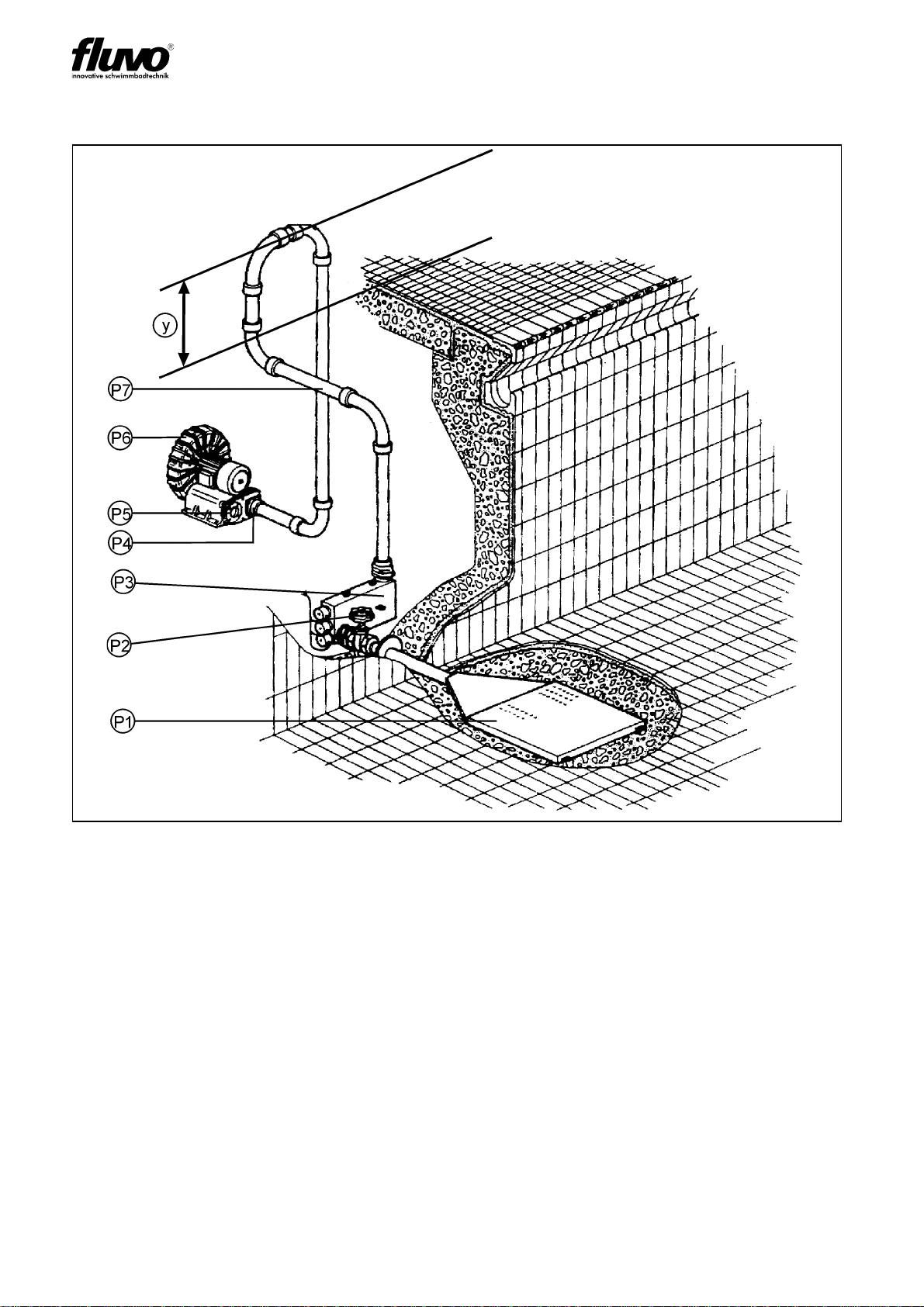
Installation situation
Fig. 5: P1 Air pad
P2 Pressure-end shut-off unit
P3 Heater (additional accessory)
P4 Pressure end
P5 Suction end
P6 Side channel blower
P7 Pipeline
Y Air loop y= min. 50 cm
The side channel blower must be installed so that the air loop is always at least y= 0.5 m
above the water level.
One side channel blower can supply several air pads with compressed air.
The air pad can be installed in the bottom. It can also be built into a bench or reclining
recess.
3.3.1 Before starting to set up, check the following

OPERATING INSTRUCTIONS
19
Side channel blower
Version: 27222 - C
Schmalenberger GmbH + Co. KG
D-72072 Tübingen / Germany
• Is the machine / system / container connection prepared according to the dimensions
of the dimension sheet / installation diagram?
• Do the concrete foundations have sufficient concrete strength (min. B 15) per
DIN 1045?
• Is the concrete foundation hardened?
• Is the surface horizontal and even?
3.3.2 Installation and set-up of the side channel blower
Side channel blowers are always placed with their feet on a base plate and are fastened
with screws.
For assembly on a foundation, the side channel blower must be aligned with a spirit level.
3.3.3 Connecting the pipelines
• For short pipelines, the nominal widths should at least match those of the side channel
blower connections. For longer pipelines, determine the most cost-effective nominal
width from case to case.
• Transition pieces to larger nominal widths should be designed with an expansion angle
of about 8° to prevent increased pressure loss.
• The suction line rises continuously to the side channel blower. Lay pipelines
continuously falling for the supply to prevent air lock from forming.
• Depending on the type of system and side channel blower, installation of backflow
prevention valves and shut-off elements is recommended.
• Expansion of pipelines due to temperature must be countered by suitable measures.
We recommend installing compensators directly between the side channel blower and
the pipeline.
Stability - risk of injury!
Side channel blowers with large drives that are installed vertically are top-
heavy. These side channel blowers must be secured against tipping during
assembly or disassembly, for example by using retaining ropes.
Note!
The side channel blower must never under any circumstances be used as a
point for securing the pipeline. No forces or moments (for example caused by
warping or heat expansion) from the pipelines may be allowed to affect the side
channel blower. Pipes must be intercepted directly before the side channel
blower and connected with no tension. Suitable compensators should be used
when doing this.
Caution - risk of injury!
If pipeline forces are exceeded, points with faulty seals may develop on the
side channel blower itself or on the flange connections, which may result in
powerful ejection of conveying medium.

OPERATING INSTRUCTIONS
20
Side channel blower
Version: 27222 - C
Schmalenberger GmbH + Co. KG
D-72072 Tübingen / Germany
• Always avoid fittings in pipelines that close suddenly (rapidly). Pressure peaks which
occur as a result of these fittings may exceed the maximum permissible housing
pressure of the side channel blower several times over! To avoid strong pressure
peaks, install pressure absorbers or air chambers
3.3.4 Electrical connection - general
The electrical connection for the side channel blower should only be made by a company
specialising in electrical systems that is approved by the power provider, taking into
consideration the technical connection requirements.
Note!
After assembly is complete or before starting up the system, the containers,
pipelines and connections must be thoroughly cleaned, rinsed and blown out
with air.
Often welding beads, pipe scale and other impurities do not come loose until
some time has passed. They must be kept out of the pipe by installing a sieve
in the suction line of the side channel blower. The open cross-section of the
sieve must be at least three times the cross-section of the pipeline to prevent
too much resistance from building up due to trapped foreign objects.
Experience shows that hat-shaped sieves containing a mesh wire net with a
mesh size of 2.0 mm and a wire diameter of 0.5 mm and made of corrosion
resistant material are effective.
Connection tasks must only be performed by a certified installation electrician,
who is approved by the responsible power provider as a specialist in electrical
installation.
For additional details, see the TAB of EVS, VBG 4 (§3) and DIN VDE 1000-10
/ 1995-5.
Applicable DIN VDE regulations 0100 and for explosion protection 0165 must
be observed.
Danger of lethal electrical shock!
Danger of electrical shock if the installation is not performed properly!
Table of contents


