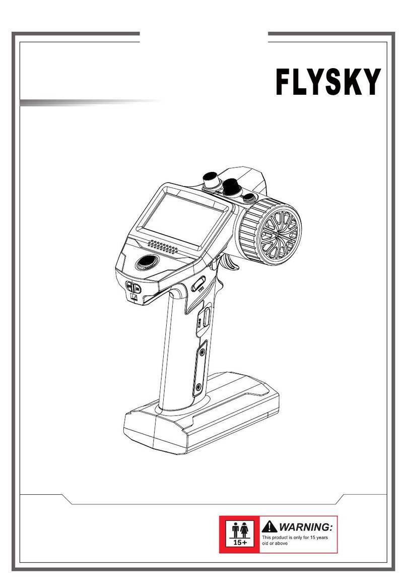
Fly Sky FS-MG7 User manual

FS-MG7
USER MANUALUSER MANUAL
Automatic Frequency Hopping
Digital System
Website

Thank you for purchasing our products.
Read the manual carefully to ensure your personal safety as well as the safety of your
equipment.
If you encounter any problems during using, please refer to this manual rst. If the
problem is still not resolved, please contact the local dealer directly or contact the
customer service sta via the website below:
http://www.ysky-cn.com

1.Safety ....................................................................................... 1
1.1 Safety Symbols ........................................................................................................................ 1
1.2 Safety Guide ............................................................................................................................. 1
2.Introduction ............................................................................... 2
2.1 Transmitter Overview .............................................................................................................. 2
2.2 Receiver Overview ���������������������������������������������������������������������������������������������������������������3
2.2.1 The LED Status of the Receiver .............................................................................................................. 3
2.2.2 Interface .................................................................................................................................................... 3
2.2.3 Antenna ..................................................................................................................................................... 3
3.Getting Started ........................................................................... 4
3.1 Transmitter Anttena ................................................................................................................. 4
3.2 Receiver and Servo Installation .............................................................................................. 4
3.3 Installing Transmitter Battery ................................................................................................. 5
4. Operation Guide ........................................................................ 6
4.1 Power-on .................................................................................................................................. 6
4.2 The LED Status of the Transmitter .......................................................................................... 6
4.3 Binding ..................................................................................................................................... 7
4.4 One-way And Two-way Switching .......................................................................................... 7
4.5 Stick Calibration ....................................................................................................................... 8
4.6 Ambient Light ........................................................................................................................... 8
4.7 Power O ................................................................................................................................. 8
5.System Functions ....................................................................... 9
5.1 Channel Description ................................................................................................................ 9
5.2 Channel Switching ................................................................................................................... 9
5.3 Channel Reverse .................................................................................................................... 10
5.4 Trim Setting ............................................................................................................................ 10
5.5 D/R Setting ............................................................................................................................. 10
5.6 Switching Model .................................................................................................................... 11
5.7 2-in-1 Mode ............................................................................................................................ 11
5.8 Beginner Mode ....................................................................................................................... 11
5.9 Failsafe .................................................................................................................................... 12
5.10 Reset Data ............................................................................................................................ 12
5.11 Idle Alarm ............................................................................................................................. 12
5.12 Sleep Mode ........................................................................................................................... 13
5.13 Oine Prompt...................................................................................................................... 13
5.14 Transmitter Voltage Alarm .................................................................................................. 13
5.15 Receiver Voltage Alarm ........................................................................................................ 13
Contents

5.16 Factory Reset ........................................................................................................................ 13
6. FS-R7D Function Instructions ................................................... 14
6.1 Attentions ............................................................................................................................... 14
6.2 Binding Instruction ................................................................................................................ 14
6.3 Car Light Control .................................................................................................................... 14
6.4 Firmware Update ................................................................................................................... 15
6.5 Failsafe .................................................................................................................................... 15
7. Customized Denition ............................................................. 16
7.1 Steering Wheel Angle Adjustment Instruction ..................................................................... 16
8. Specications .......................................................................... 18
8.1 Transmitter Specications .................................................................................................... 18
8.2 Receiver Specications ......................................................................................................... 19
9. Package Contents .................................................................... 20
10. Certications ......................................................................... 21
10.1 DoC Declaration ................................................................................................................... 21
10.2 CE Warning ........................................................................................................................... 21
10.3 FCC Statement ..................................................................................................................... 21
10.4 Environmentally friendly disposal ..................................................................................... 22

Website
1
• Misuse of this product may lead to serious injury or death. To ensure the safety of you
and your equipment, read this manual and follow the instructions.
• Make sure the product is properly installed in your model. Failure to do so may result in
serious injury.
• Make sure to disconnect the receiver battery before turning o the transmitter. Failure to
do so may lead to unintended operation and cause an accident.
• Ensure that all motors operate in the correct direction. If not, adjust the direction rst.
• Make sure the model stays within the systems maximum range to prevent loss of control.
• Do not use the product at night or in bad weather like rain or thunderstorm. It can cause
erratic operation or loss of control.
• Do not use the product when visibility is limited.
• Do not use the product on rain or snow days. Any exposure to moisture (water or snow)
may cause erratic operation or loss of control.
• Interference may cause loss of control. To ensure the safety of you and others, do not
operate in the following places:
• Near any site where other radio control activity may occur
• Near power lines or communication broadcasting antennas
• Near people or roads
• On any body of water when passenger boats are present
• Do not use this product when you are tired, uncomfortable, or under the inuence of
alcohol or drugs. Doing so may cause serious injury to yourself or others.
• The 2.4GHz radio band is limited to line of sight. Always keep your model in sight as a
large object can block the RF signal and lead to loss of control.
Prohibited Mandatory
1.Safety
1.1 Safety Symbols
Pay close attention to the following symbols and their meanings� Failure to follow these warnings could cause damage,
injury or death�
1.2 Safety Guide
Warning • Not following these instructions may lead to major injuries.
Danger • Not following these instructions may lead to serious injuries or death.
Attention • Not following these instructions may lead to minor injuries.

FS-MG7
Automatic Frequency Hopping Digital System
Website
2
2.Introduction
The FS-MG7 is a 7-channel transmitter which is compatible with the 2.4GHz ANT Automatic Frequency Hopping
Digital System, featuring compact design, comfortable to the hand, ergonomic. In addition, the ESC parameters can
be set at the transmitter side. The transmitter also has a beginner mode for beginners.
2.1 Transmitter Overview
Steering Wheel (CH1)
Switch CH4 (CH4)
REV Button
D1 LED
D2 LED
Switch CH3 (CH3)
Switch CH5 (CH5)
ST- Button
BIND Button
TH- Button
LOGO Sticker
ST+ Button
TH+ Button
Power Switch
Throttle Trigger (CH2)
Battery Compartment
4*AAA Batteries inside
Lanyard Hole
CH6 Button (CH6)
CH7 Button (CH7)
Ambient Light
RGB Color
Type-C USB Port

Website
3
2.2.1 The LED Status of the Receiver
2.2.2 Interface
2.2.3 Antenna
All the channel interfaces are 2.54mm*3 standard pins, and all light interfaces are 2.54mm*2 standard pins, they are
used for connecting the receiver to each terminal part of the model.
It is an external antenna.
The LED status indicates the power supply state of the receiver and its working state.
O: The receiver is not powered on.
Light on in red: The receiver is connected to the power supply. It works normally.
Fast ashing: The receiver is in the bind mode.
In three- ash-one-o mode: It is waiting for rmware updating or in rmware updating progress.
Slow ashing: The LED ashes slowly when the transmitter is powered o, unbound, or no signal.
2.2 Receiver Overview
Attention
• Do not put the antenna close to the metal materials, because this will aect the signal strength
of the receiver. Keep the receiver's antenna at least 1cm away from conductive materials such
as carbon or metal.
Caution • Do not pull the antenna of the receiver. Do not tie the antenna and the servo cable together.
[1] CH1(PPM) [12] Right turn signal light interface
[2] CH2 [13] Left turn signal light interface
[3] CH3 [14] LED
[4] CH4 [15] Antenna
[5] CH5 [16] Bind button
[6] CH6 [17] + (Power anode for light interface)
[7] CH7 [18] - (Power cathode for light interface)
[8] Flash(Strobe) light interface [19] S (Signal pin )
[9] Backup light interface [20] + (Power anode for channel interface)
[10] Tail light interface [21] - (Power cathode for channel interface)
[11] Headlight interface
Take FS-R7D receiver as an expample.
[1]
[2]
[3]
[4]
[5]
[6]
[7]
[8][9][10]
[15]
[11] [12] [13]
[16]
[14]
[18]
[17] [20] [21][19]

FS-MG7
Automatic Frequency Hopping Digital System
Website
4
3.Getting Started
Prior to operations, please install the battery and connect devices according to the sequence and guide as described
in this chapter.
3.1 Transmitter Anttena
3.2 Receiver and Servo Installation
The transmitter has a built-in antenna. When the transmitter starts to work, the antenna automatically
operate, without additional operations.
Make sure that the receiver is mounted in an appropriate location within the model, to ensure a stable signal,
maximum range and to mitigate external interference, follow these guidelines:
Pay attention to the following when installing the receiver:
1. Make sure the receiver is not installed near motors or other sources of electrical noise.
2. Keep the receivers antenna away from conductive materials such as carbon or metal. To ensure normal function
make sure there is a gap of at least 1cm between the antenna and the conductive material.
Caution • To prevent damage do not power on the receiver during installation.
Steering Servo
Throttle Servo
Aux Channel Servo
Aux Channel Servo
Aux Channel Servo
Aux Channel Servo
Aux Channel Servo
CH1
CH3
CH2
CH4
CH5
CH6
CH7
Connect the servos to the receiver according to the digram below.

Website
5
3.3 Installing Transmitter Battery
Danger • Only use specied battery (X4 AAA batteries).
Danger • Do not open, disassemble, or attempt to repair the battery.
Danger • Do not crush/puncture the battery, or short the external contacts.
Danger • Do not expose to excessive heat or liquids.
Danger • Do not drop the battery or expose to strong shocks or vibrations.
Danger • Always store the battery in a cool, dry place.
Danger • Do not use the battery if damaged.
Battery Type: AAA
Follow the steps below to install the batteries:
1. Open the battery compartment cover.
2. Insert 4 AAA batteries with the correct polarity. Make sure it is
connected with the correct polarity to avoid damage.
3. Replace battery compartment cover.
Press to slide the cover as illusrtated
to open the cover.

FS-MG7
Automatic Frequency Hopping Digital System
Website
6
4. Operation Guide
After setting up, follow the instructions below to use the product.
Follow the steps below to turn on the transmitter:
1. Check to make sure that the batteries are fully charged and installed correctly.
2. Toggle the Power Switch to the ON position.
4.1 Power-on
4.2 The LED Status of the Transmitter
Attention • Operate with caution in order to avoid damage or injury.
The D1 LED of this transmitter is used to indicate the status of the transmitter, and the D2 LED is used to indicate the
status of the receiver which is in two-way binding with the transmitter, as shown in the following table:
Note: For safety always power on the transmitter before the receiver.
LED LED Status Transmitter Status Note
D1
Flash in green, orange and red
repeatedly for 2S
Standby mode (The transmitter is in normal mode
after powering on without toggling any control)
Slow ash once in red Switch to CH1
Switch channels (1 to 3~7),
used to adjust the positive
and negative direction,
Trim, and travel of CH3-
CH7 channels.
Slow ash three times in red Switch to CH3
Slow ash four times in red Switch to CH4
Slow ash ve times in red Switch to CH5
Slow ash six times in red Switch to CH6
Slow ash seven times in red Switch to CH7
Solid on in green High voltage
Transmitter voltageSolid on in orange Medium voltage
Slow ash in red Low voltage
Slow ash in green for 3S 2-in-1 mode switching 2-in-1 mode
Slow ash in green for 3S 2-in-1 mode after powering on
Two-ash-one-o in green for 3S Switching beginner mode Beginner mode
Two-ash-one-o in green for 3S Beginner mode after powering on
Fast ash in red In binding Binding (or Calibration,
refer to funtion description)
Solid on in red Binding is successful (or in calibration mode)
Fast ash in red & green
alternately for 2S
From one-way mode to two-way mode
One-way mode or two-way
mode switching
Fast ash in red & green
alternately for 2S
From two-way mode to one-way mode
Fast ash in red & green
alternately for 3S
In one-way after powering on
Three-ash-one-o in red Receiver is not bound or disconnected TX and RX disconnect
Red gradual light In Idle state Idle alarm
Orange gradual light In Sleep state Sleep mode
Fast ash in red for 3S Factory reset Factory reset

Website
7
4.3 Binding
The transmitter and receiver have been pre-bound before delivery. If you are going to rebind, follow the steps below
to rebind. The transmitter supports two-way binding and one-way binding. The receiver will ruturn information
after the two-way binding is nished.
1. Turn on the transmitter while pressing the BIND button, the transmitter will enter bind mode, at the time, the D1
LED ash fast in red.
2. Put the receiver to enter bind mode.
3. The binding process is completed when the LED of the receiver stops ashing and is solid on (The transmitter will
exit the bind mode automatically).
4. Check to make sure the transmitter and receiver are working correctly, if there are any issues or unexpected
operation arise, follow the steps above to bind again.
Notes:
1. If the transmitter enters bind mode with one-way mode, the LED of the receiver will be in slow ashing state.
After the receiver LED becomes slow ashing, then restart the transmitter. At this time, the receiver LED is solid
on, indicating the binding is successful.
2. The binding steps may vary according to the receiver model. Visit the Flysky ocial website to check the manual
of the receiver or other relevant information.
Notes:
1. After the switching between one-way and two-way, you need to re-bind the receiver.
2. In the 2-in-1 mode, the switching between one-way and two-way is not allowed.
D2
Slow ash in red Standard receiver voltage: Low
Voltage state of the receiver
connected
Slow ash in red 2-in-1 receiver with voltage level: Ultra-low
Solid on in green 2-in-1 receiver voltage level: High
Solid on in orange 2-in-1 receiver voltage level: Medium
Solid on in red 2-in-1 receiver voltage level: Low
The transmitter supports two communication modes: one-way and two-way. Please select the appropriate
communication mode as required (two-way by default).
To switch from two-way to one-way, do as follows:
• Press the REV button, turn the steering wheel of the transmitter clockwise to the maximum travel, and power it on.
At this time, the D1 LED ashes red and green alternately, and the buzzer sounds twice shortly in Tone 1 cyclically.
It indicates that the transmitter has switched to one-way.
When the transmitter is powered on in one-way mode, the D1 LED will ash red and green alternately for 3S, and the
buzzer will sound once shortly in Tone 2.
When switching from one-way to two-way, adopt the same steps as above.
When the transmitter is powered on in two-way mode, the D1 LED ashes green, orange and red alternately for 2S.
4.4 One-way And Two-way Switching

FS-MG7
Automatic Frequency Hopping Digital System
Website
8
4.5 Stick Calibration
Calibrate the maximum and minimum travel of the steering wheel and throttle trigger. The factory calibration is
completed. If you need to recalibrate the transmitter, follow the steps below:
4.6 Ambient Light
The ambient light may be in any of the following states: o, blue solid on, blue gradual light, dazzling gradual light,
throttle trigger position indication state, and transmitter voltage indication state. By default, it is o. The switching
step is as follows:
• Press and hold the CH7 button of the transmitter for 2S to switch the state. To switch once, press it once. You can
perform this operation cyclically.
1. Turn the transmitter steering wheel clockwise to the maximum travel, push the throttle trigger forward to the
maximum travel, and power it on. That is, enter the stick calibration mode. At this time, the D1 LED is solid on in
red and the buzzer sounds once shortly with Tone 1 cyclically.
2. Steering wheel calibration: Turn the steering wheel to the maximum and minimum travel in clockwise and
counterclockwise respectively, then return to the neutral position.
3. Throttle trigger calibration: Push the throttle trigger forward and backward to the maximum and minimum travel,
respectively, then return to the neutral position.
4. Press the BIND button to save and exit the calibration mode.
• If the calibration is successful, you can press the BIND button to exit the calibration mode, and the buzzer can
sound once shortly with Tone 2 cyclically.
• If the calibration fails, pressing the BIND button is invalid. That is, it is unable to exit the calibration mode.
4.7 Power O
Danger • Make sure to disconnect the receiver power before turning o the transmitter. Failure to
do so may lead to damage or serious injury.
Follow the steps below to turn o the system:
1. Disconnect the receiver power.
2. Toggle the transmitter's Power Switch to the OFF position.
Notes:
1. For the throttle trigger position indication state, the ambient light is blue when the throttle trigger is in the
neutral position, and the light turns from blue to red while in other positions. Perform the stick calibration rst
prior to using ambient light.
2. For the transmitter voltage indication state, the ambient light color is the same as the D1 LED color of the LED
indicating transmitter voltage, refer to 4.2 The LED Status of the Transmitter.

Website
9
Channel Assigned Control Function(Normal mode) Function (2-in-1 mode)
CH1 Steering Wheel
Steering, to control the left/right steering.
Turn the steering wheel in clockwise or counterclockwise to
control the left/right steering and light signals.
Same as Normal mode
CH2 Thottle Trigger
Thottle, to make the model car forward and backward.
Push or pull the throttle trigger to control the model car forward
or backward, as well as light signals.
Same as Normal mode
CH3 Switch CH3 Switch the model car speed level.
Toggle the control to switch. Same as Normal mode
CH4 Switch CH4 Switch the model car speed level.
Toggle the control to switch.
Switch the ESC battery
type
CH5 Switch CH5
Enable/disable the winch function, or switch the model car
speed level.
Toggle the control to enable/disable the winch function, or
switch the speed.
Set the operate mode of
ESC
CH6 CH6 Button Switch the model car speed level.
Toggle the control to switch. Control light signals
CH7 CH7 Button
Four-wheel steering switching channel
It is used to set the wheels that control the model car steering,
i.e., front wheel steering, front and rear wheels reversal steering,
front and rear wheels in the same steering, and rear wheel
steering. You can press the control to switch. It is suitable
for partial crawler types with steering on both front and rear
wheels. Switch one state per press of the control. By default, it
is front wheel steering.
Note: When switching, the buzzer's states are indicated by
the number of beeps with Tone 1: front wheel steering (beep
once), front and rear wheels reversal steering (beep twice),
front and rear wheels in the same steering (beep 3 times), and
rear wheel steering (beep 4 times).
Switch the drag brake
strength of ESC
5.System Functions
This section focuses on the functions and how to use them.
The transmitter outputs a total of 7 channels, the function assignment and settings are as follows.
5.1 Channel Description
Note: For details function in 2-in-1 mode, refer to 5.7 2-in-1 mode.
Note: Allowed to switch cyclically.
To switch among CH1 and CH3 to CH7. Follow the step below:
• In case of power-on, press the BIND button twice quickly within 1S. The number of ashes of D1 LED indicates the
switch to a specic channel. See 4.2 The LED Status of the Transmitter.
5.2 Channel Switching

FS-MG7
Automatic Frequency Hopping Digital System
Website
10
This function is used to adjust the travel range value of the channel.
For 2-in-1 mode, only CH1-CH4 travel range value can be adjusted. For non-2-in-1 mode, CH1-CH7 travel range value
can be adjusted.
• When the steering wheel is located in the maximum travel or minimum travel, press the ST+/- button to adjust CH1
and CH3-CH7 travel range value. By default, the CH1 travel range value is adjusted. To adjust CH3-CH7, rst switch
to the corresponding channel. When CH7 is set to rear wheel steering only, CH7 travel range value can be adjusted
by pressing the ST+/- button in CH1.
• When the throttle trigger is at the maximum or minimum travel, press the TH+/- button to adjust CH2 travel range
value.
ST+/TH+: Increase the travel value. ST-/TH-: Decrease the travel value. Travel range: 0-120%, by default, it is 100%,
the step is 5%.
When the servo setting action takes eect, the buzzer will beep once shortly in Tone 2. You can press and hold it for
quick adjustment. The buzzer will sound for seconds when it reaches the end.
5.5 D/R Setting
To reverse the output direction of the channel.
For 2-in-1 mode, it can adjust the direction of CH1 and CH2 only. For non-2-in-1 mode, it can adjust the direction of
CH1-CH7.
• When the steering wheel is at the maximum or minimum travel, press the REV button to adjust CH1 and CH3-CH7
reverse steering. Press once to switch once. By default, it adjusts the steering of CH1. To adjust the steering of CH3-
CH7, switch to the corresponding channel rstly. When only CH7 is set to rear wheel steering mode, CH7 can be
reversed by pressing the REV button under CH1. When the reverse steering action takes eect, the buzzer will beep
once shortly in Tone 1.
• When the throttle trigger is at maximum or minimum travel and the steering wheel is in the neutral position, press
the REV button to reverse CH2. To switch once, press once. When the channel reverse steering action takes eect,
the buzzer will beep once shortly in Tone 2.
This function is used to adjust the channel trim.
For 2-in-1 mode, only CH1-CH4 trim can be adjusted. For non-2-in-1 mode, CH1-CH7 trim can be adjusted.
• When the steering wheel is in the neutral position, press the ST+/- button to adjust CH1 and CH3-CH7 trim. By
default, the CH1 trim is adjusted. To adjust CH3-CH7, rst switch to the corresponding channel. When CH7 is set to
rear wheel steering only, CH7 trim can be adjusted by pressing the ST+/- button in CH1.
• When the throttle trigger is in the neutral position, press the TH+/- button to adjust the CH2 trim.
ST+/TH+: Press to increase the trim value. ST-/TH-: Press to decrease the trim value. The trim range: -120 us~120 us.
The step is 4us. By default, it is 0.
When the trim setting action takes eect, the buzzer will beep once shortly in Tone 1. You can press and hold it for
quick adjustment. The buzzer will beep twice shortly when the trim is over Neutral. The buzzer will sound once for
seconds when it reaches the end.
5.3 Channel Reverse
5.4 Trim Setting

Website
11
The transmitter supports two modes in two-way communications: 2-in-1 mode and normal mode. By default, it is
normal mode.
• Press and hold the BIND and CH6 buttons of the transmitter, and power it on. At this time, the D1 LED ashes
slowly for 3S, and the buzzer beeps twice in Tone 2, and the transmitter will be in 2-in-1 mode or normal mode.
You can power it o and save the settings. In case of power-on, if the D1 LED ashes slowly in green for 3S and the
buzzer beeps twice in Tone 2, this is 2-in-1 mode; if the D1 LED ashes green, orange and red quickly for 2S, this is
normal mode.
In 2-in-1 mode, the function settings are as follows:
• Control the model car lights by pressing the CH6 button. It is reversed once when you press once.
• Set the ESC operation mode through the CH5 switch: Forward/backward/brake mode or forward/backward mode.
By default, it is forward/backward/brake mode. It is switched once when you toggle the CH5 switch once. When
the mode is switched to forward/backward, the buzzer will beep once in Tone 1. Otherwise, it beeps twice.
• Toggle the CH4 switch to switch the ESC battery type: Li-ion and Ni-MH. By default, it is Li-ion. It is switched once
when you toggle the CH4 switch once. When switching to Li-ion battery, the buzzer will beep twice in Tone 2.
Otherwise, it beeps once.
• Switch the ESC drag brake strength by pressing CH7 button: 0%, 50%, 75% and 100%. By default, it is 0%. The drag
brake strength is switched once when you press it once. When the strength is switched to 0%, the buzzer beeps
once in Tone 1. When the strength is switched to 50%, the buzzer beeps twice. When the strength is switched to
75%, the buzzer beeps for three times. When the strength is switched to 100%, the buzzer beeps for four times.
The transmitter supports ve sets of models.
• Press and hold the CH6 and CH7 buttons of the transmitter and power it on. That is, it enters the mode of
switching model. When the switching is successful, the buzzer will sound at dierent times in prompt tones. See
the following table.
Model Buzzer(Sound in Tone 2)
Model1 Sound once shortly
Model2 Sound twice shortly
Model3 Sound three times shortly
Model4 Sound four times shortly
Model5 Sound ve times shortly
5.7 2-in-1 Mode
5.6 Switching Model
Notes:
1. After the model is switched successfully, the RF module changes into two-way mode, and the transmitter enters
standby mode.
2. Allowed to switch cyclically.
This transmitter supports the beginner mode.
• Press and hold the CH6 button of the transmitter, turn the steering wheel to the maximum travel in
counterclockwise, and power it on, the transmitter will be the beginner mode or the normal mode. If the switching
5.8 Beginner Mode

FS-MG7
Automatic Frequency Hopping Digital System
Website
12
The transmitter will go into idle alarm state when there is no operation over 10 minutes.
• When the transimitter is in idle alarm state, the D1 LED will be in red gradual light state, and the buzzer will sound
twice quickly in cycle with Tone 1 and Tone 2 for prompt. Operations of any control on the transmitter will cancel
the alarm, as a result of the exit of the idle alarm state.
To reset the function data of the model using currently to default value.
• Press and hold the BIND and CH7 buttons of the transmitter, and power it on, to reset the data. When the setting is
successful, the buzzer will sound once for seconds with Tone 2.
Note: These will not be reset, such as the failsafe setting, binding information, 2-in-1 mode and one-way/two-way
data.
5.11 Idle Alarm
5.10 Reset Data
It is used for the safety of the model and the operator when the receiver cannot receive signals from the transmitter
normally (out-of-control).
By default, it is not set. In this case, the receiver channel has no output.
• In the normal power-on state, set the control corresponding to the channel to be congured with failsafe to the
preset position. Then, press and hold the Bind button for 3S to set the channel value of the current output to the
failsafe value. When the setting is successful, the buzzer will sound once for seconds with Tone 1.
5.9 Failsafe
Notes:
1. If the transmitter binds with a 2-in-1 ESC receiver, the receiver will automatically enter the brake mode after out-
of-control.
2. Restore to the default setting in case of re-binding.
Notes:
1. After switching to the beginner mode, the throttle D/R is a half of normal mode.
2. The setting will be save when the transmitter turns o.
is successful, The D1 LED works in two-ash-one-o mode in green for 3S cyclically and the buzzer will sound once
shortly with Tone 2.
In case of power-on, you can judge the mode of the transmitter according to the D1 LED status and buzzer sound: If
the D1 LED works in two-ash-one-o mode in green for 3S cyclically and the buzzer sounds once shortly with Tone 2,
it is the beginner mode; if the D1 LED quickly ashes green, orange and red for 2S, it is the normal mode.

Website
13
When a 2-in-1 receiver has connected and the transmitter has been in idle alarm state over 2 minutes, it will enter
the sleep mode.
• In this mode, the D1 LED will be in orange gradual light state, the buzzer and RF will turn o. The transmitter is not
responsive in case of operations of any control. To exit the sleep mode, power o the transmitter and restart it.
When the transmitter is in two-way mode, once it detects the bound receiver has turned o, or disconnected over
2S, the D1 LED will work in three-ash-one-o mode for prompt.
It is used to indicate the transmitter voltage state. It gives an alarm when the voltage is medium or low.
• Transmitter Voltage > 5 V: The D1 LED is solid on in green. 4.2 V < Transmitter Voltage < 5 V: The D1 LED is solid on
in orange. Transmitter Voltage < 4.2 V: The D1 LED ashes slowly in red and the buzzer beeps once shortly in Tone 1
cyclically.
It is used to indicate the voltage state of the connected receiver and alarm.
• For standard receivers, when the voltage is lower than 4.2 V, the D2 LED ashes slowly in red and the buzzer beeps
once in Tone 1 cyclically.
• For 2-in-1 receivers, when the voltage is high, the D2 LED is solid on in green; when the voltage is medium, the D2
LED is solid on in orange; when the voltage is low, the D2 LED is solid on in red and the buzzer beeps twice shortly
in Tone 1 cyclically; when the voltage is ultra-low, the D2 LED ashes slowly in red and the buzzer beeps for three
times shortly in Tone 1 cyclically.
This function is used to restore the transmitter to the factory default state.
• Press and hold REV and CH7 buttons of the transmitter and power it on. That is, restore to the factory default state.
When the setting is successful, the D1 LED quickly ashes in red for 3S and the buzzer sounds twice for seconds
with Tone 2.
5.12 Sleep Mode
5.13 Oine Prompt
5.16 Factory Reset
5.14 Transmitter Voltage Alarm
5.15 Receiver Voltage Alarm

FS-MG7
Automatic Frequency Hopping Digital System
Website
14
6. FS-R7D Function Instructions
Note: Refer to 2.2 receiver overview for the information of the receiver's interfaces.
6.1 Attentions
6.2 Binding Instruction
6.3 Car Light Control
This section instruct how to use FS-R7D receiver and the attentions.
FS-R7D is a light group 7-channel receiver in compliance with the ANT protocol with a single external antenna, two-
way transfer-back function. It can output PWM signals and light control signals, featuring the compact design. It can
adapte to a variety of car models.
If needs to rebind the receiver and the transmitter, refer to 4.3 Binding for details.
• Make sure the product is installed and calibrated correctly, failure to do so may result in serious injury.
• Make sure the receiver's battery is disconnected before turning o the transmitter, failure to do so can result out
of control. Unreasonable setting of the Failsafe may cause accidents.
• Make sure the receiver is mounted away from motors, electronic speed controllers or any device that emits
excessive electrical noise.
• Keep the receiver's antenna at least 1cm away from conductive materials such as carbon or metal.
• Do not power on the receiver during the setup process to prevent loss of control.
The lights are mainly controlled through CH1 and CH2, i.e. the working status of the lights is controlled by hand
wheel and trigger.
The details are as follows:
Name Working Mode Trigger Condition Remarks
Left Turn Light Slow ash Left turn
Right Turn Light Slow ash Right turn
Headlight Solid ON Steering wheel clockwise fast rotation
for three times
After setting the channel reverse, it
is counterclockwise.
Strobe Light Fast Flash Steering wheel counterclockwise fast
rotation for three times
After setting the channel reverse, it
is clockwise.
Tail Light Solid ON Brake
Backup Light Solid ON Back up
Notes:
1. After the receiver is powered on, all lights perform self-test immediately. After the lights are on for 1 second, they
are o.
2. By default, the headlights and strobe lights are o.
3. Steering CH1 and throttle CH2 can automatically identify the neutral position.

Website
15
6.4 Firmware Update
6.5 Failsafe
This receiver supports two failsafe modes: ON and OFF. You can set it at transmitter side. Please refer to Failsafe in
the previous description.
The rmware of this receiver is updated through the FlyskyAssistant (Only version 3.0 or later is supported. The
rmware of FlyskyAssistant is available on the Flysky ocial website).
This receiver can be updated via the following two ways:
1. After the binding between the transmitter and the receiver (the LED of the receiver is solid on), connect the
transmitter to the computer, then open the FlyskyAssistant on the computer to update the rmware.
2. Connect the transmitter to the computer. Then put the receiver to enter the forced update mode by referring to
the followingway (The LED of the receiver works in three-ash-one-o mode repeatedly). Afterwards, open the
FlyskyAssistant on thecomputer to update the rmware.
• Power on the receiver rst, then press and hold the BIND button for more than ten seconds, when the LED of
the receiver works in three-ash-one-o mode repeatedly, then release the BIND button.

FS-MG7
Automatic Frequency Hopping Digital System
Website
16
7. Customized Denition
7.1 Steering Wheel Angle Adjustment Instruction
1 2 3
4 5 6
First insert a hexagonal
screwdriver into the screw hole
used to secure the steering
wheel.
Hold the side of the steering
wheel, and at the same time
turn the hexagonal screwdriver
counterclockwise until the
screw is completely loose and
remove it.
Hold the transmitter body, and
pull out the steering wheel to
remover the wheel.
Pinch the brake pad with two
ngers and take out upwardly.
As shown, put two screws into
the screw holes on both ends of
the brake pad. Use a hexagonal
screwdriver to x the screws in
turn.
Carefully remove the sponge
from the steering wheel.
Fllow the steps below to adjust the angle of the steering wheel.
Table of contents
Other Fly Sky Remote Control manuals
Fly Sky
Fly Sky FS-i6X User manual
Fly Sky
Fly Sky FS-HW-G4P User manual
Fly Sky
Fly Sky FS-i6 User manual

Fly Sky
Fly Sky FS-GT2B User manual
Fly Sky
Fly Sky Paladin PL18 EV User manual
Fly Sky
Fly Sky Noble NB4+ User manual
Fly Sky
Fly Sky Noble NB4 User manual
Fly Sky
Fly Sky FS-VK-G4P User manual

Fly Sky
Fly Sky FS-MG41 User manual

Fly Sky
Fly Sky FS-IT4 User manual
Fly Sky
Fly Sky FS-i6S User manual

Fly Sky
Fly Sky Noble NB4 User manual
Fly Sky
Fly Sky FS-i10 User manual

Fly Sky
Fly Sky FS-i6 User manual

Fly Sky
Fly Sky FS-VK-G4P User manual
Fly Sky
Fly Sky FS-lT4S User manual
Fly Sky
Fly Sky FS-i6X User manual
Fly Sky
Fly Sky VK-R4A User manual
Fly Sky
Fly Sky FS-GT3B User manual
Fly Sky
Fly Sky FS-CT6A User manual
