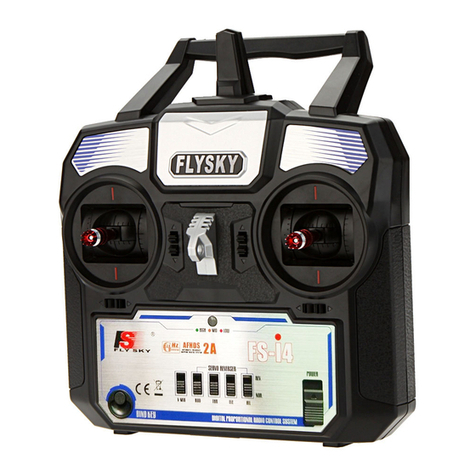
Fly Sky Eurgle th9x User manual

Th9x
M A N U A L E U R G L E T H 9 X N G

Author: Thomas Husterer, Josef Glatthaar
Version: V1.1
V1.2 Firmware r46
V1.3 Firmware r5
©2010 Thomas Husterer

Contents
Chapter 1: Introduction 5
Chapter 2: Performance 6
Chapter 3: Menu structure 7
3.1 Basic concepts .................................................................................. 7
3.2 Main screen .................................................................................... 8
3.3 Model-specific Setup ........................................................................... 9
Model selection 1/7 ............................................................................. 9
Model basic setup 2/7 ......................................................................... 10
Expo function 3/7 ............................................................................. 11
Expo function etails ......................................................................... 12
setup trim values 4/7 .......................................................................... 12
Mixer 5/7 ..................................................................................... 13
Edit Mixer ................................................................................... 14
Curve 6/7 ..................................................................................... 15
Edit Curve .................................................................................... 15
Limits 7/7 .................................................................................... 15
3.4 Global setup, diagnosis and calibrating ......................................................... 16
Global Setup I ................................................................................ 16
Global Setup II (Options) ...................................................................... 17
Trainer Mode ................................................................................. 17
Software Version .............................................................................. 18
key diagnosis ................................................................................. 18
iagnosis of Analogue inputs and calibrating of battery voltage measurement .................... 19
Calibrating the sticks .......................................................................... 19
Chapter 4: unction 21
4.1 Power on sequence ............................................................................ 21
4.2 ata flow ..................................................................................... 21
Calibrating ................................................................................... 22
Expo ......................................................................................... 22
Trim ......................................................................................... 24
Mixer ........................................................................................ 24
Curves ........................................................................................ 24
Limits ........................................................................................ 25
4.3 Trainer mode ................................................................................. 25
4.4 Flash programming ........................................................................... 25
Programming plug connections ................................................................ 25
Fuse Bits ..................................................................................... 26
4.5 LC Back light ............................................................................... 26
Chapter 5: Programming examples 28
3

5.1 Glider or powered plane with rudder, elevator and aileron ....................................... 28
Assignment of the channels .................................................................... 28
Special control functions: ..................................................................... 28
Explanation .................................................................................. 29
5.2 Glider with 4 flaps ............................................................................ 29
Assignment of the channels: ................................................................... 29
Special control functions: ..................................................................... 30
Explanation ................................................................................... 30
5.3 Powered plane with retractable landing gear and landing gear doors ............................. 31
5.4 Helicopter with 120° Swash Plate .............................................................. 31
5.5 Helicopter with 120° Swash Plate and Pitch .................................................... 32
5.6 Phase switch .................................................................................. 32
4

1Introduction
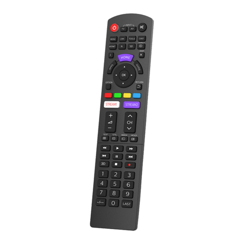
he remote control Eurgle th x, also sold under some other labels like Imax,
Turborix or Turnigy manufactured by FlySky is a very low cost 2.4GHz radio
with impressive hardware-features but with a less convincing firmware.
T
5

2 Performance
2Performance
16 model memories
two stage mixer allows any combination of input-channels to form output
signals
adjustable signal delay for each mixer line even with different values for up
and down movement
4 pitch curves with 5 or nodes
dynamic memory management
servo reverse feature and tunable servo range limits
expo and dual rate features
tunable battery warning
support for lighted display (hardware upgrade necessary)
trainer mode with selectable channel behavior
stick calibration
timer with three modes
option-switches for several features.
6

3Menu structure
3.1 Basic concepts
six buttons are available for operator interface.
key function
key left move to previous menu
ore move cursor left, or decrease a value
key right move to next menu
or move cursor right or increase a value
key up move cursor up
or increase a value
key
down
move cursor down
or decrease a value
key
menu
open a sub menu
or confirm an action
key exit
exit current menu and return to the calling menu. This is only valid
when the cursor is positioned at the top right edge
else move the cursor to the top right edge
LONG
key exit
return immediately to the uppermost screen
Key can be pressed short or long or very long and each time another
action can be triggered
Most actions appear immediately after a sort key-press.
When a key is pressed for long time, then an action is repeated
In some cases a long-time key press is required to trigger the action. This
behavior is used for preventing unintentional operations in the standard
screen.
7

3 Menu structure
There is no undo functionality. If you change a value or remove something
by mistake then you have to re-edit the former values manually.
Attention!! Values are stored to the EEPROM-Memory with a short time-
delay after the last key press. The storage procedure is announced by
some buzzer-beeps
3.2 Main screen
Screen contents:
the current model name (NURI)
a cursor selection either at Th x or at the model name
the battery voltage (6. V)
the remaining timer value
the output values by numbers..
..or in a graphical representation
the trimmer values in a graphical representation.
key function
LONG Open menu set 'Global Setup'
LONG Open menu set 'Model-specific Setup'
LONG Move to menu 'Timing statistic'
Change output view mode from graphical view to numeric view
8

Trim
keys
Change the Trim Values.
Attention!! the values are evaluated in a non linear manner.
move cursor left
move cursor right
LONG Open menu set 'Global Setup'
or Open menu set 'Model-specific Setup'
LONG reset timer
stop timer alarm.
3.3 Model-specific Setup
This set of menus does handle any settings which are related to one unique
model. All menus are consecutively numbered and they are cycled by pressing the
left or right key. The menu 1/7 is used to select one of 16 memory slots which holds
any setup-data related to one model.
key function
cycle through the model menus
3.3.1 Model selection 1/7
Select one of 16 memory-slots by cursor movement up or down. Then activate this
slot by pressing exit or by cycling to the next model-menu.
Please notice the free memory value in the title line. If this value gets lower than
about 200 bytes then you should remove some model slots. Properly storage opera-
tion is only guaranteed if enough memory is available.

3 Menu structure
key function
Select memory slot by cursor movement.
cycle to next menu
back to main screen
select current line for edit commands.(model name is blinking)
move current line up or down.
duplicate the selected model into next free memory slot.
3.3.2 Model basic setup 2/7
In edit field 'Name' you can change the model name. Move the cursor right
to a character position and then change the value.
In field 'Proto' you can select one of several transmitter protocols. Normally
you select PPM here.
In field Timer you can preset a count down start value and a count down
mode. This value is then decremented according to the selected mode
OFF / ABS / THR / THR%.
OFF: no decrementing.
ABS: always count down.
THR: only count down when the Throttle Stick is not in its neutral position.
THR%: like before, but count down more or less fast dependent to the
THR-position.
When the cursor is positioned to RM then the whole model memory can
be removed by pressing menu
key function
10

1. move cursor up and down
2. move cursor left right
3.
oder
change values
4. reset cursor to the upper right edge
5a leave this menu
5b cycle to the next menu
LONG Remove this model memory. Only valid if Cursor is positioned at RM.
3.3.3 Expo function 3/7
In this menu you can set up an exponential behavior for each of the four sticks. Select
a value between -100 up to +100.
You can open a sub menu 'Expo function Details' to see even more settings like
a dual-Rate-switch and a dual rate expo function.
key function
1. move cursor up and down
2. change values
3a open menu Expo function Details
3b reset cursor to the upper right edge
4a leave this menu
4b cycle to the next menu
11

3 Menu structure
3.3.4 Expo function Details
You can change the two expo values and the expo switch in this menu. In the diagram
you see the shape of the expo function.
.
3.3. setup trim values 4/7
Here you can swap the trim values to a base value. After this operation, the trim val-
ues in the main screen are repositioned to zero.
key function
1. move cursor up and down
2a
.
add the trim value to the base value and reset the trim value to zero
2b. reset the base value,
3. reset cursor to the upper right edge
4a leave this menu
4b cycle to the next menu
12

3.3.6 Mixer /7
This menu is the most important menu of the whole arrangement. You can combine
here several Inputs like stick values, pots-values or constants into each one of the
output channels. Additionally there are four Helper channels which are used as tem-
porary values X1-X4. These values are calculated first, and can then be used as
inputs.
Each mixer line can contain a weight, an input channel, an optional switch, a curve
and some delay values. Switches are available in a normal or in an inverted style.
Curves:
There are 8 kinds of curves: -- , >0 , <0 , |x| , cv1, cv2, cv3 and cv4
- : no curve, or y=x
>0 : y=x | x>0, else y=0
<0 : y=x | x<0 else y=0
|x| y=|x|
Cv1..Cv4 Use one of four user defined curves.
Cv1 and Cv2 have 5 nodes at x=-100, -50, 0, 50, 100;
Cv3 and Cv4 have nodes at x=-100, -75, -50, -25, 0, 25, 50, 75, 100
key function
1. move cursor at or between two lines
2a
.
change weight value.
2b. Open menu 'Edit-Mixer'. if the cursor was positioned between two lines,
then a new line is generated, else the current line is edited.
3. reset cursor to the upper right edge
4a leave this menu
4b cycle to the next menu
13

3 Menu structure
3.3.7 Edit Mixer
In this menu you can adjust all the details of one single mixer line.
SRC: select the input channel R D, THR, ELE, AIL, P1, P2, P3, X1, X2, X3, X4,
MAX F L.
with MAX you can emit a constant value 0 or +100%
with F L you can emit a constant value 100% or +100%
PRC: weight from -125% to +125%
CURVE: one of eight curve types.
SWTCH: a switch. Dependent from the SRC-Value the switch acts in two different
manners.
When SRC=MAX or FUL then the switch selects one of two fixed values as input
values and the line is calculated with the whole set of parameters.
When SRC!=MAX or FUL then the switch can switch on the whole line or it can
switch off the whole line. In the last case none of the remaining parameter has any
effect.
SPEED: These two values determine the speed in which rising or falling input val-
ues are propagated to the output channel
RM: This field is used to remove the whole mixer-line.
key function
1. move cursor up and down
2a
.
change values
2b remove whole line,. Tis is only valid when cursor is at RM.
2c edit curve. This is only valid when cursor is at CV1 CV4
3. leave menu
14

3.3.8 Curve 6/7
3.3.9 Edit Curve
key function
1. move cursor up / down
3. change value.
select predefined curve. This is only valid if cursor is at PRESET
4 leave menu
3.3.10 Limits 7/7
In this menu you can revert output channels and you set up the output value limits.
15

3 Menu structure
key function
1. move cursor up / down
2. move cursor to a column.
3. change value.
4 reset cursor to the upper right edge
5a leave menu
5b cycle to the next menu
3.4 Global setup, diagnosis and calibrating
In this group of menus is combined any setups that are not model specific.
The menus are numbered as well and can be cycled with the left and right keys as
the group above.
key function
Cycle through the menus. This is only valid if the cursor is positioned at the upper
right edge.
3.4.1 Global Setup I
In this menu you can change some global values.
Screen contents:
The contrast value.
The warning level for the battery voltage alarm.
16

A switch which is used to control the lcd-back light.
Attention! This feature requires a hardware extension..
The mode selection is used to assign a specific function to any input stick.
At the end it changes the labels which are shown in all other menus where
input values are selected.
key function
1. move cursor up / down
2. change values
3. reset cursor to the upper right edge
4a
.
leave this menu
4b cycle to the next menu
3.4.2 Global Setup II (Options)
In this menu you can select several options like warnings or the key-beep.
3.4.3 Trainer Mode
Here you can decide how each Input stick is handled in trainer mode.
Each line shows:
RUD the input channel in the trainer radio
off no student activity
17

3 Menu structure
+= trainer and student values are both added and then used as input
signal
:= only the student controls this channel
8 the students values are weighted by this value
ch1 this is the channel number which is received from the students
radio. In the students radio this channel has to be connected to
one single stick.
RUD Here you can define a switch which controls this trainer line
Cal: This line shows the input values which are received from the stu-
dents radio. If you press Menu, then the current values are defined
as reference values for the student inputs.
3.4.4 Software Version
Shows the current software version
key function
1a
.
leave this menu
1b cycle to the next menu
3.4. key diagnosis
18

Show the current levels of any key,switch or trim-switch
key function
1a
.
leave this menu
1b cycle to the next menu
3.4.6 Diagnosis of Analogue inputs and calibrating of battery voltage
measurement
Shows the values of all analogue inputs with 10 bit resolution. The stick-values are
also shown in %.
Value number eight shows the battery voltage. Here you can also calibrate the
shown voltage level.
key function
1. move cursor up and down
2. change shown battery voltage.
3. reset cursor to the upper right edge
4a
.
leave this menu
4b cycle to the next menu
3.4.7 Calibrating the sticks
1

3 Menu structure
With the help of this menu you can calibrate the values of all four sticks in a four step
procedure.
The procedure requires moving the sticks to a given position and then press cursor
down while holding the sticks in this position ..
key function
1. move cursor to SetMid
move all sticks into the center position and hold them
2. move cursor to SetLow
move all sticks to the lower left edge and hold them.
3. move cursor to SetHigh
move all sticks to the upper right edge and hold them.
4. move cursor to Ready
now its finished
5 change to previous menu and check the shown percentage values.
20
Table of contents
Other Fly Sky Remote Control manuals
Fly Sky
Fly Sky FS-VK-G4P User manual

Fly Sky
Fly Sky FS-i6 User manual
Fly Sky
Fly Sky Nirvana NV14 User manual
Fly Sky
Fly Sky FS-T6 User manual
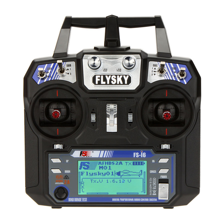
Fly Sky
Fly Sky FS-i6 User manual
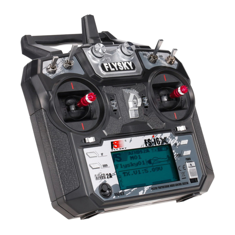
Fly Sky
Fly Sky FS-i6X User manual

Fly Sky
Fly Sky FS-T6 User manual
Fly Sky
Fly Sky FS-TH9X User manual
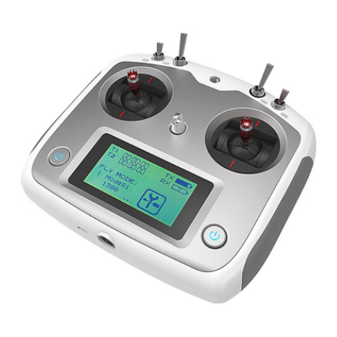
Fly Sky
Fly Sky FS-i6S User manual
Fly Sky
Fly Sky FS-lT4S User manual

Fly Sky
Fly Sky SM001 User manual
Fly Sky
Fly Sky FS-G7P User manual

Fly Sky
Fly Sky FS-IT4 User manual

Fly Sky
Fly Sky Noble NB4 User manual

Fly Sky
Fly Sky FS-GT3 User manual

Fly Sky
Fly Sky FS-VK-G4P User manual
Fly Sky
Fly Sky VK-R4A User manual
Fly Sky
Fly Sky Noble NB4 User manual

Fly Sky
Fly Sky FS-GT3 User manual

Fly Sky
Fly Sky FS-i10 User manual
