Fly Sky Paladin PL18EV User manual

User Manual
Copyright ©2021 Flysky Technology co., ltd

Thank you for purchasing our product, an ideal radio system for beginners or experienced
users alike.
Read this manual carefully before operation in order to ensure your safety, and the safety
of others or the safe operation of your system.
If you encounter any problem during use, refer to this manual rst. If the problem persists,
contact your local dealer or visit our service and support website for help:
http://www.ysky-cn.com

Table of Contents
目录
1. Safety ........................................................1
1.1 Safety Icons .......................................................................1
1.2 Safety Guide ......................................................................1
2. Battery Safety Instructions ......................2
3. Product Description .................................3
3.1 System Features ................................................................3
3.2 Transmitter Overview .......................................................4
3.2.1 Transmitter Antenna ...........................................................6
3.2.2 Status Indicator ....................................................................6
3.2.3 Trim Switch ...........................................................................6
3.2.4 Adjustment of Multiplex Stick Assembly ..........................6
3.2.5 Power Buttons .....................................................................7
3.2.6 Charging Modes ..................................................................7
3.3 Receiver Overview (Take FGR12B as an example) .....8
3.3.1 Receiver Antenna .................................................................8
3.3.2 Status Indicator ...................................................................8
3.3.3 Ports ......................................................................................8
4. Pre-operation Setup .................................9
4.1 Receiver and Servo Installation .......................................9
5. Operation Guidelines .............................10
5.1 Power On .........................................................................10
5.2 Binding ............................................................................10
5.3 Pre-operation Checks .....................................................11
5.4 Power O .........................................................................11
6. UI .............................................................12
6.1 UI Overview .....................................................................12
6.1.1 Status Bar (Top) ..................................................................12
6.1.2 Quick Access .......................................................................13
6.2 Menu UI ............................................................................13
6.2.1 Function Icons ....................................................................13
6.3 Gimbal, Knob and Switch Assignment ..........................13
7. Function Settings ...................................14
7.1 Reverse ...........................................................................14
7.2 End Points .......................................................................14
7.3 Subtrim ............................................................................15
7.4 Conditions .......................................................................15
7.5 Trims ................................................................................16
7.6 Rate and EXP (Exponential Function) ............................16
7.7 Channels Oset ...............................................................17
7.8 Channels Delay ...............................................................17
7.9 Mixs ..................................................................................18
7.10 Track mixing ..................................................................18
7.11 A.B.S. ..............................................................................19
7.12 Logic Switches ..............................................................20
7.13 Timers ...........................................................................21
7.14 Throttle curve ................................................................21
7.15 Function assignment ....................................................22
7.16 Display Servos ...............................................................22
7.17 Model setting .................................................................23
7.18 Sensors ..........................................................................25
7.18.1 Display Sensor ..................................................................25
7.18.2 Choose Sensors ...............................................................27
7.18.3 Air Pressure Sensor..........................................................27
7.19 Help Center ...................................................................27
8. RX Setup ..................................................28
8.1 Bind with a receiver ........................................................28
8.2 Failsafe .............................................................................28
8.3 Range test ........................................................................28
8.4 RX protocol .....................................................................29
8.5 Set to PWM conv .............................................................29
8.6 i-BUS setup ......................................................................30
8.7 Low voltage voice alarm .................................................30
8.8 Low signal voice alarm ...................................................31
8.9 Servo frequency ..............................................................31
8.10 Servo midpoint .............................................................31
8.11 RX update .....................................................................31
8.12 About Receiver ..............................................................32
9. RF setup ..................................................33
10. System ..................................................34
10.1 Language .......................................................................34
10.2 Units ...............................................................................34
10.3 Sound ............................................................................34
10.4 Vibration ........................................................................34
10.5 Backlight Timeout ........................................................34
10.6 Backlight Brightness .....................................................35
10.7 Standby timeout ..........................................................35
10.8 Auto Shutdown .............................................................35
10.9 Screen quick access ......................................................35
10.10 Switches setup ...........................................................35
10.11 Calibration ...................................................................36
10.12 Factory Reset ...............................................................36
10.13 TX Firmware Update ...................................................36
10.14 About Paladin EV.........................................................36
11. Product Specication ...........................37
11.1 Transmitter Specications(PL18 EV) .........................37
11.2 Receiver Specications (FGr12B) ............................38
12. Package Contents .................................39
13. Certication ..........................................40
13.1 DoC ................................................................................40
13.2 CE Warning ....................................................................40
13.3 Appendix 1 FCC Statement ..........................................40
14. Environmentally friendly disposal .......41
1
• Improper use of this product may lead to serious injury or death to the user and others.
To ensure the safety of yourself and others read and follow the instructions set out in
the user manual.
• To avoid damage to the model, make sure that the product and model are installed
correctly before use.
• Always power o the receiver before the transmitter. Powering o the receiver before
the transmitter could lead to loss of control.
• Before use make sure that all the servos and motors are moving in the correct direction.
• Make sure to remain within range to prevent loss of control.
• Do not y at night or in bad weather like rain or thunderstorm. It can cause erratic
operation or loss of control.
• Do not use the product when the visibility is limited.
• Do not use the product on rainy or snowy days. Should any type of moisture (water or
snow) enter any component of the system, erratic operation and loss of control may
occur.
• Interference could cause loss of control. To ensure the safety of you and others, do not
operate in the following places:
• Near any site where other radio control activity may occur.
• Near high voltage power lines or communication broadcasting antennas.
• Near water with passenger boats nearby.
• Near high voltage wires or communication/broadcast antennas.
• Do not use this product if you are tired, uncomfortable or when using substances that
may impair your ability to use the product safely.
• The 2.4GHz frequency band requires line of sight from the transmitter to receiver at all
times. Avoid large obstacles that could block or interfere with the signal.
• In order to ensure good signal quality, do not hold the transmitters antenna during use.
• Parts of the model, such as motors or ESC’s may remain hot for a period of time after
use and can cause severe burns.
Prohibited Mandatory
1. Safety
1.1 Safety Icons
Pay attention to the following icons and their meanings. Failure to follow these guidelines can result in equipment
damage or personal injury.
1.2 Safety Guide
CAUTION • Not following these instructions may lead to major injuries.
WARNING • Not following these instructions may lead to minor injuries.
DANGER • Notfollowingtheseinstructionsmayleadtoseriousinjuriesordeath.
2
2. Battery Safety Instructions
Danger
This products battery is rechargeable
and non-removable. Do not remove
the battery from the product.
Do not charge the battery in direct
sunlight, in a hot car or near
anything hot such as cookers etc.
Do not charge without ventilation.
Do not use near ammable liquids or
gasses.
Charge before use.
Failure to charge the battery before use may
lead to a crash.
Do not solder, repair, modify or
disassemble the battery.
Do not touch the charger or battery
during charging.
May cause burns
Keep the battery away from any
heat source if it is leaking or causing
strange smells.
May catch re or explode.
WARNING
Do not charge batteries that show
any evidence of damage, aging,
leakage or exposure to liquids.
Do not expose the battery to liquids.
Do not use a damp battery. Keep your hands
try during use and do not leave batteries in areas
with lots of moisture.
Do not touch the positive and
negative terminals of the battery
together.
Do not throw the battery into a re.
Do not throw or impact the battery.
May cause re or an explosion.
Put some tape on the battery's
terminals before recycling.
If the short circuit causes re, heat, rupture, etc.
Do not store the battery in dusty or
humid environments.
Remove dust from the power connector before
plugging in.
Do not charger the battery when
exposed to extreme heat or cold.
May lead to a drop in battery performance.
To ensure maximum performance always charge
the battery within the temperature range of
10℃ ~30℃ .

3
3. Product Description
PL18EV is an 18-channel transmitter dedicated to engineering vehicles, equipped with 2.4GHz AFHDS
3 (third-generation automatic frequency hopping digital system). The standard conguration is an FGr12B
receiver!
3.1 System Features
AFHDS3 (third-generation automatic frequency hopping digital system) is a newly developed digital wireless
system. It is compatible with single antenna bidirectional real-time data packet transmission and data stream
transmission. With the advantages that come with the WS2A wireless system and the new 2.4GHz chip, the system
can dynamically set: number of channels, channel resolution, range, anti-interference requirements and latency to
meet the needs of dierent users.
Single Antenna
Bidirectional
Real-time Data
Transmission
The receiver can receive data from the transmitter and the transmitter can receive data from the
receiver, this includes data from sensors, such as temperature and speed and support the i-BUS.
This gives more control over the aircraft and constant information on its current status.
Uncorrected Data
Transmission
The independent uncorrected data transmission module is built into RF system; it can send
many dierent types of data including ight control data.
Intelligent RF
conguration
Depending on hardware, certication, the amount of data to be transmitted, anti-interference,
latency and distance requirements, the system intelligently adapts the corresponding RF
conguration to meet the requirements of the user.
Multi-channel
Frequency
Hopping
This systems bandwidth ranges from 2.402GHz to 2.480GHz. This band is divided in 140
channels. Each transmitter hops between 16 channels (32 for Japanese and Korean versions) in
order to reduce interference from other transmitters.
Unique ID
Recognition
System
Each transmitter and receiver has it's own unique ID. Once the transmitter and receiver have
been paired, they will only communicate with each other, preventing other systems accidentally
connecting to or interfering with the systems operation.
Low Power
Consumption The system is built using highly sensitive low power consumption components, maintaining
high receiver sensitivity, while consuming as little as one tenth the power of a standard FM
system, dramatically extending battery life.
4
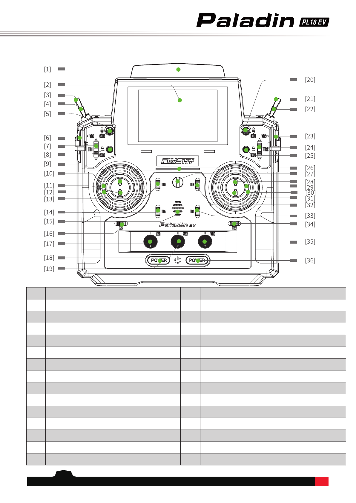
3.2 Transmitter Overview
Front View:
[1] Antenna [16] TR7 Trim
[2] 320*480px Screen [17] VRA Knob
[3] SWF 2 Position Switch [18] VRB Knob
[4] SWE 3 position switch [19] Power Button
[5] SWB 3 Position Switch with Self-return [20] SWD 3 Position Switch with Self-return
[6] VRD Knob [21] SWH 3 Position Switch with Self-return
[7] TR1 Trim [22] SWG 3 Position Switch with Self-return
[8] SWA Button [23] VRE Knob
[9] SWJ Button [24] TR2 Trim
[10] Left Gimbal [25] SWC Button
[11] SWI Button [26] Transmitter Status Indicator
[12] VRF Knob [27] Lanyard Eye
[13] TR3 Trim [28] SWL Button
[14] TR5 Trim [29] VRG Knob
[15] Speaker [30] Right Gimbal
5
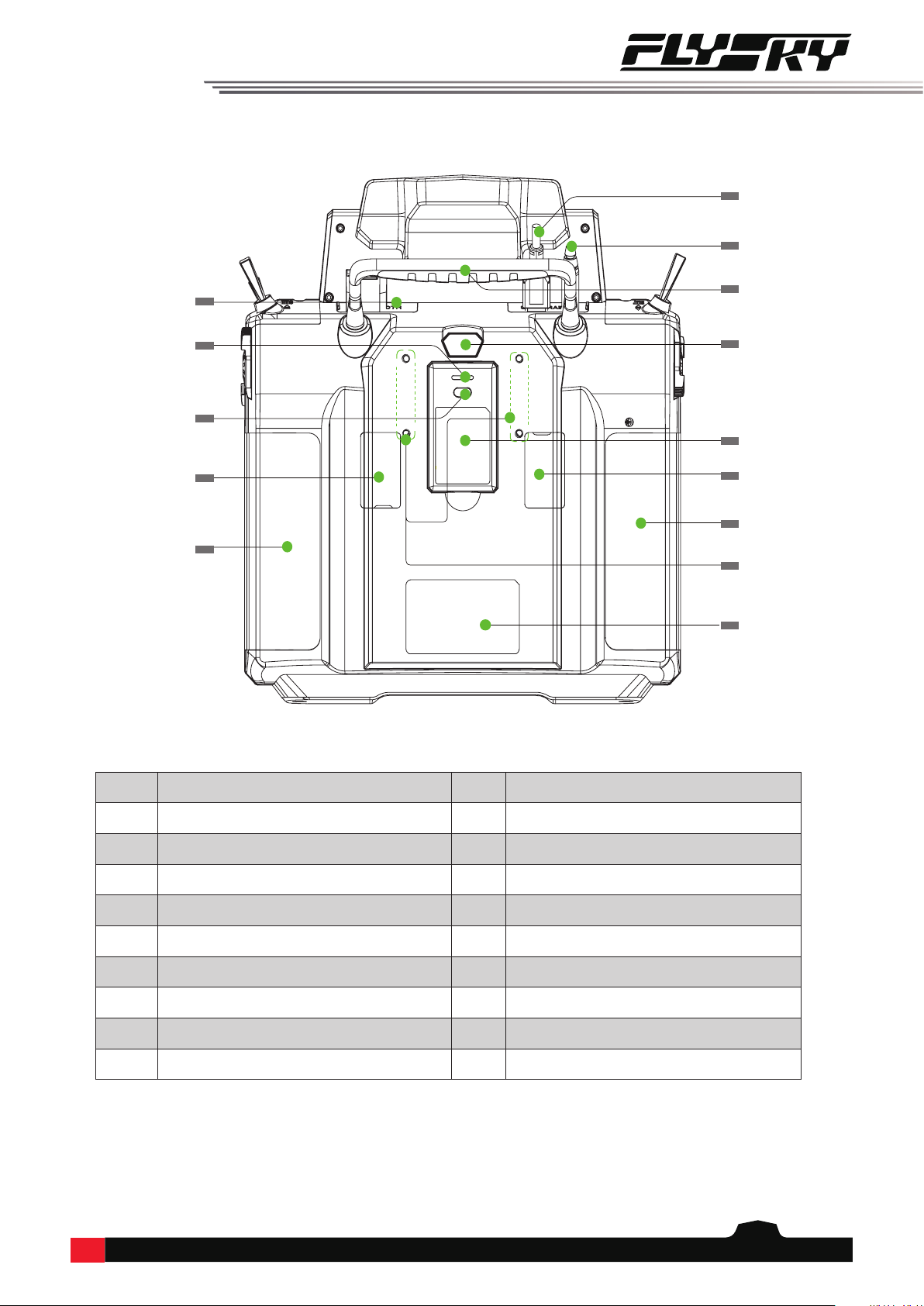
Back View:
[31] SWK Button [41] Grip
[32] TR4 Trim [42] Micro USB Port
[33] TR6 Trim [43] Trainer Port
[34] TR8 Trim [44] Grip
[35] VRC Knob [45] FRM301 Press to release FRM301
[36] Power Button [46] FRM301 RF Module
[37] Bluetooth Module Port [47] Gimbal Tension Adjustment
[38] FRM301 Status Indicator [48] Grip
[39] FRM301 Button [49] RF Module Port
[40] Gimble Tension Adjustment [50] Wireless Charging Area
[37]
[38]
[39]
[41]
[42]
[43]
[44]
[46]
[48]
[45]
[50]
[40] [47]
[49]

6
3.2.1 Transmitter Antenna
PL18 EV transmitter has a built-in antenna. When the transmitter starts the work, the antenna operates
automatically, without being operated separately!
3.2.2 Status Indicator
The status indicator displays the transmitter's power and operating status.
When the screen is on:
• If RF is enabled without connecting the receiver (one-way bind receiver), the blue indicator is on.
• If RF is disabled, the yellow indicator is on.
• If the receiver is connected bi-directionally, the green indicator is on.
When the screen is o:
1. If RF is enabled without connecting the receiver (one-way bind receiver), the breathing indicator can change to
cyan, magenta, and yellow.
2. If RF is disabled, the breathing indicator is yellow.
3. If the receiver is connected bi-directionally, the breathing indicator can change to red, green, and blue:
• in case of bind: the green indicator is on (fast ashing).
• in case of an alarm: the red indicator is on (slow ashing).
• in case of power-on: the blue is on until the power-on is successful.
• in case of power-o: the current color is not changed until the product is shut down successfully and the LED
is o.
3.2.3 Trim Switch
There are 8 groups of trims in the transmitter for adjusting the center point of the device. Each toggle of the trim
corresponds to a change in value that can be set to 5 units by default. If you keep pressing, the trim position starts to
change rapidly.
3.2.4 Adjustment of Multiplex Stick Assembly
①
②
③
④
⑤
⑥
⑦
⑧
Note • To ensure a good signal do not cover or block the antenna.
Multiplex Stick Assembly Front View Stick
Used to adjust the centering state and resilience of the 5D multiplex stick.

7
Function Settings:
By adjusting the tension screws on the back of the radio, gimbal stick can be either self-centering or non self-centering, as well as changing
stick tension preference.
Available options:
Left gimbal as example:
Non Self-returning
Self-return and
Non self-return
①.⑤ left & right side gimbal sticks automatic self centering ②.⑥ left & right side gimbal stick vertical
tension
③.⑦ left & right side gimbal stick horizontal tension ④.⑧ throttle stick vertical friction
1. Use a Phillips screwdriver to adjust the screw ① counterclockwise until the gimbal reaches its center point.
2. Adjust screw ④ counterclockwise to adjust the Frictional strength.
3. If you need to adjust the strength of the return, adjust screw ② to the middle, and strengthen the clockwise force,
and vice versa as needed.
1. Use a Phillips screwdriver to adjust the screw ① clockwise so that the gimbal is no longer at its center point.
2. Adjust the screw ④ clockwise to strengthen or reduce the Frictional strength.
3. If you need to adjust the strength of the return, adjust screw ② to the middle, and strengthen the clockwise force,
and vice versa as needed.
• After adjusting clockwise to the tightest, the counterclockwise adjustment range should be controlled under 5
rounds. Over-adjustment will cause the screw to come out.
3.2.5 Power Buttons
To prevent false triggering, there are two switches on the lower part of the transmitter. The power-on/-o is
triggered when both switches are pressed.
3.2.6 Charging Modes
PL18EV can be charged in two ways:
1. Plug the standard USB cable into the charging port
for charging
2. Use the wireless charging dock to charge it (as shown
in the gure)
Notes:
• Charge it within the safe range [4h@5V*2A/7h@5V*2A
(wireless charging)]. Overcharging may lead to
battery damage;
• To prolong the service life of the battery, properly
discharge if you want to store it for a long time (that
is, not fully charged). In addition, you need to charge
it regularly to prevent damage due to not-operation
for long term;
• Please use the standard charging cable of this
transmitter. Improper use may cause damage to the
battery and aect its service life.
8
3.3 Receiver Overview (Take FGR12B as an example)
CAUTION • Do not pull, bend or tie the receivers antenna or connect it to a servo.
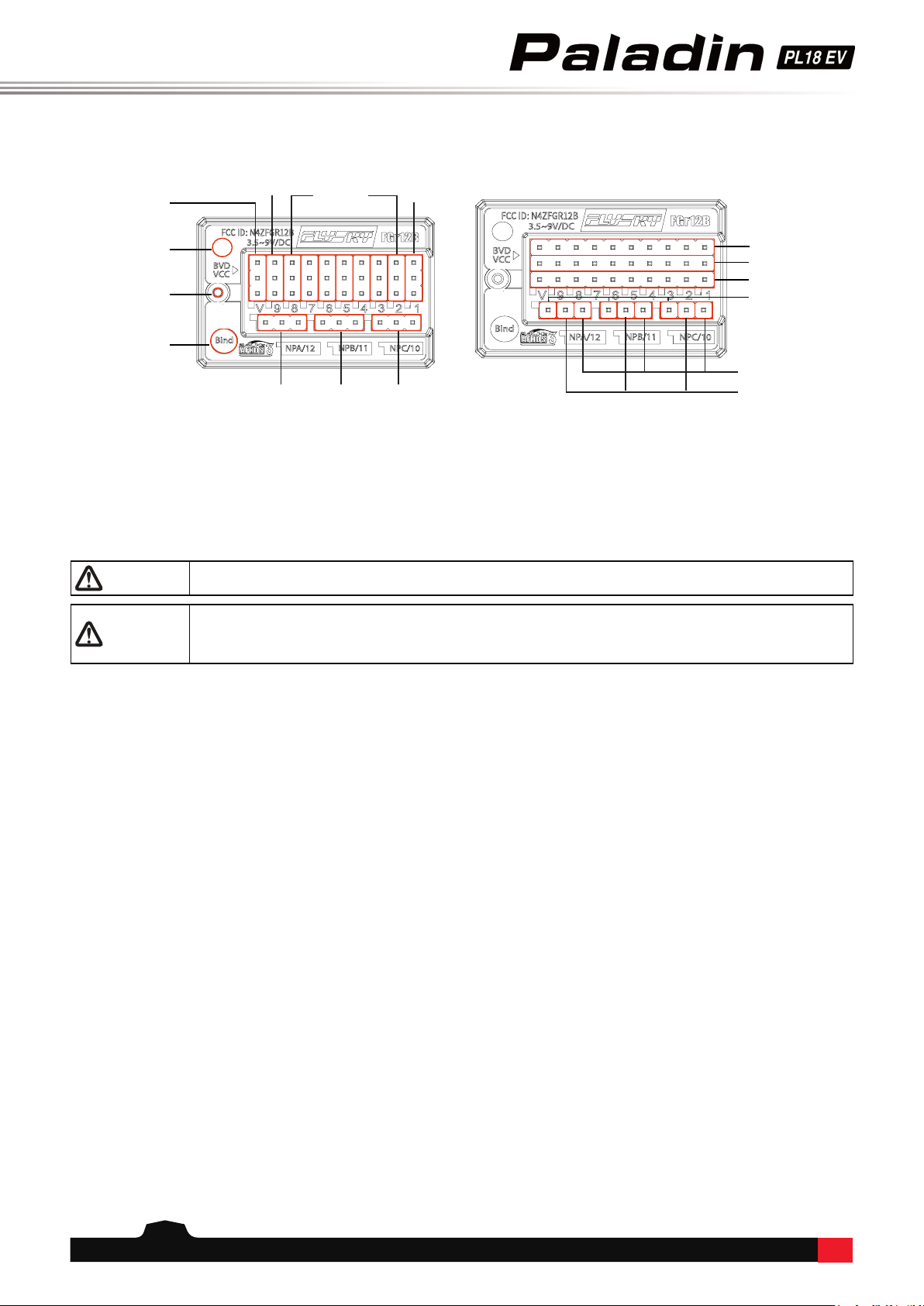
3.3.3 Ports
These ports are used to connect the receiver to the various components of the model.
• PPM/CH1: Connect to the servo, or output the PPM signal.
• CH1 - CH12: Can be connected to the servo, power supply or other components.
• BVD/VCC: Used to detect the battery voltage and connect the power cable.
• i-BUS in sensor interface (SENS/CH12/NPA): Used to connect each sensor.
• bind button: Used to realize the bind between receiver and transmitter.
• i-BUS out serial bus interface (SERVO/CH12/NPA): Connects i-BUS module to extend the channel and output i-BUS
or S-BUS signal.
• For denition of the NPA~NPD interface, see the receiver's manual.
Note:
• BVD function and NPA~NPD function will be implemented in the next version of rmware;
• For this transmitter matched with the receiver, see the matching table on the ocial website. For specic operation
mode matched with other receivers, refer to the above contents.
3.3.1 Receiver Antenna
The FGR12B uses AFHDS 3 (third generation automatic frequency hopping digital system), which enables bi-
directional transmission.
CAUTION
• Keep the receivers antenna away from conductive materials such as carbon or metal.
To ensure normal function make sure there is a gap of at least 1cm between the
antenna and the conductive material.
CH8-CH2 PPM/CH1
CH9(NPD)
VCC/BVD
LED
Antennav
BIND
(CH12/NPA) CH11(NPB) CH10(NPC)
S(Signal pin)
+(Power positive)
-(Power supply ground)
S(Signal pin)
+(Power positive)
-(Power supply ground)
3.3.2 Status Indicator
The status indicator is used to indicate the power and operating status of the receiver.
• O: The receiver power is not connected.
• Steady red: The receiver is connected to the power supply and is working properly.
• Fast ashing: The receiver is in bind mode.
• Slow ashing: The paired transmitter is powered o or signal is lost.
9
Make sure that the receiver is mounted in an appropriate location within the model, to ensure a stable signal,
maximum range and to mitigate external interference, follow these guidelines:
Pay attention to the following when installing the receiver:
1. Make sure the receiver is not installed near ESCs or other sources of electrical noise.
2. Keep the receivers antenna away from conductive materials such as carbon or metal. To ensure normal function
make sure there is a gap of at least 1cm between the antenna and the conductive material.
4. Pre-operation Setup
Follow the instructions and guidelines in this chapter before use.
4.1 Receiver and Servo Installation
Note • Topreventdamagedonotpoweronthereceiverduringinstallation.
10
1. Check to make sure the receiver is installed correctly and that the receiver is powered o.
2. Press and hold both power buttons until the screen lights up.
3. Power on the receiver.
5. Operation Guidelines
Follow these guidelines to set up the transmitter and receiver.
5.1 Power On
Follow the steps below to power on:
Note • The system is now active, be cautious to not cause damage or personal injury.
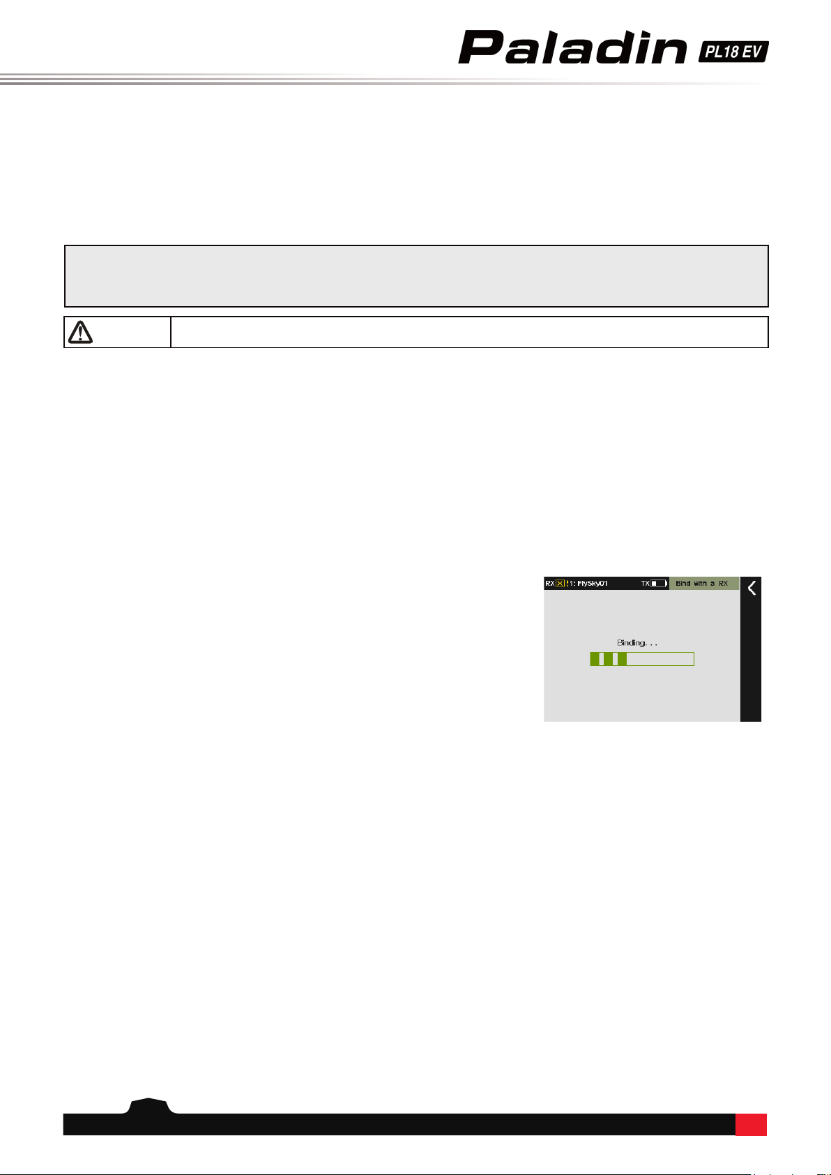
5.2 Binding
The transmitter and receiver have been pre-bound at the factory.
If you need to rebind or bind a new receiver follow the steps below:
1. Power on the transmitter, touch the function menu icon then enter the
RX setup menu.
• If you want to change the RF standard, please select [RF standard] in [RF
setup] menu. The system default standard is AFHDS3 2-way (for more
information about RF, see [9. RF Setup].
2. Make the receiver enter bind state; (For the specic bind modes, see the
manual of dierent models of receivers).
3. Touch [Bind with a receiver], to enter bind mode.
4. Dierence of successful bind under two specic RF standards:
• If you choose [AFHDS3 2-way], when the receiver indicator is on,
indicating a successful bind. The transmitter automatically exits
the bind interface.
• If you choose [AFHDS3 1-way], when the receiver indicator is slow
ashing, the transmitter manually exits the bind interface, and the
receiver indicator is on, indicating a successful bind.
5. Check that the transmitter, receiver and model are all working as
expected. If there are any abnormal movements, repeat the steps above.
11
1. Inspect the entire system to make sure that everything is working as expected.
2. Perform a range test as outlined in the [8.3 Range Test] section of the user manual.
DANGER • Do not use the model if there are any abnormal behaviors during the test.
DANGER • Do not exceed the maximum rated range during use.
CAUTION • Interference from other transmitting devices may reduce signal quality.
5.3 Pre-operation Checks
Always perform the following steps before each operating:
1. Power o the receiver.
2. Press and hold both of the transmitters power buttons until the screen powers o.
5.4 Power O
Follow these steps to power o the system:
DANGER • Toavoidanyriskofloosingcontrolofthemodel,alwayspoweroffthereceiver
beforepoweringoffthetransmitter.
12
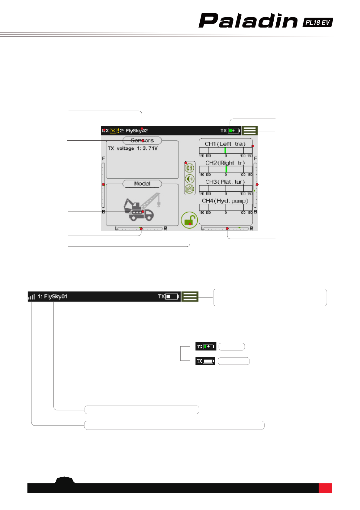
6.1 UI Overview
The main interface displays information related to the model such as sensor information and function status.
Signal strength (This bar is not displayed if a receiver is not connected)
Function menu icon: Touch this icon to
enter the function menu.
6.1.1 Status Bar (Top)
6. UI
This is an introduction to the transmitter's UI.
Model name
Transmitter power
status
Function menu icon
Sensor
information
Status Bar
TR5 trim value
Model type
TR7 trim value
Lock screen
button
Channel display
TR6 trim value
TR8 trim value
Charging
Battery Full
Currently selected model number and name
Signal strength

13
Screen Lock Screen unlocked
Function Disabled Function active
Restore to default Function select
Assign switches Set curve type
For all operating modes. For current operating mode.
Touch this area to access the [Display selection ] menu.
Up to 4 sensors can be displayed.
For more information refer to section [7.18] of this
manual.
Touch this area to select any four channels for display.
6.1.2 Quick Access
Touch this area to quickly access the [Models] setting
interface.
6.2 Menu UI
This section is a quick introduction on how to use the UI.
6.2.1 Function Icons
6.3 Gimbal, Knob and Switch Assignment
This interface can be used to assign the functions of all multiplex
sticks, knobs, switches and keys of the transmitter.
Path: [Func assign]-[click any channel, such as channel 1]-[Control] to
access the interface. For details, see [Func assign].
• Switches (SWA~SWK) dene turn-on/-o. You can dene the
downward/central/upward switch as turn-on.
• The stick can be used to simulate a linear change of the stick data.
• The knob (VRA~VRG) can be used to adjust data. The knob data
can be simulated as a linear change.
• Assign Logic Switch (LSW) to dene function turn-on/-o.

14
Function Settings:
This function can reverse the direction of travel for all 18 channels.
[Normal]: indicates that this channel output is the default direction;
[Reverse]: indicates that the channel's direction of travel has been
reversed.
• If a new model is connected make sure that all the servos
are moving in the right direction.
• Move each stick to make sure that the control surfaces are
moving in the correct directions.
Touch the box to the right of the channel name to toggle reverse for
that channel. If there is a tick in the box it means that the channel is
reversed.
7. Function Settings
This chapter introduces the main system functions.
Function Settings:
This function can be used to adjust the maximum servo volume of
18-channel servos, with the adjustment ranging from 0 to 150%.
[Up side]: range of movement above the channel center point.
[Down side]: range of movement below the channel center point.
Green box indicates the currently selected object.
Green progress bar indicates current real-time output of servo
position.
Steps:
1. Select the channel to be adjusted to enter the submenu.
2. Click the icon or toggle the sticker (switch/knob) corresponding to
the channel to select [High End] or [Low End].
3. Use the + and – icons to change the servo volume ratio.
7.1 Reverse
This function reverses the direction of motion for each channel.
7.2 End Points
This function changes the max range of movement for each channel.
Every model is different, as such many have different requirements when it comes to how far a control surface
should move, if a control surface moves too far it may damage the model. The End points function limits the range
of movement for each channel to prevent this.
Note: If the channels center point is not in the right position it will be impossible to set the outer limits of the
channel movement properly. If this is an issue use the Subtrim function to move the center point rst.
15
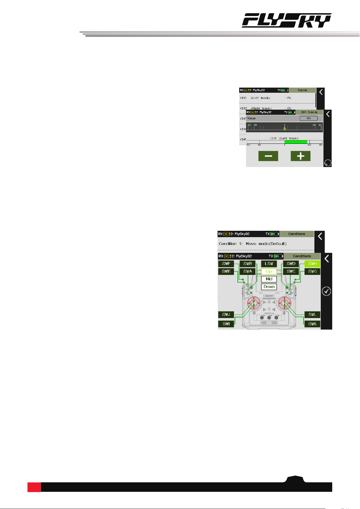
7.3 Subtrim
This function is used to adjust the center point of each channel.
Due to the structure of some models the servos center point may need to be adjusted so that when at rest all the
control surfaces line up properly.
When using this function make sure that the stick, knob etc. is at its center position.
7.4 Conditions
Conditions is divided into move mode and work mode. The two modes can be done with different settings to
achieve the same operation in dierent modes corresponding to dierent eects. When the same stick is used to
control the mobile mode or arm, this function can be used to assign the control mode in two working modes for
achieving the menu switch. The title shows the current conditions state. You can set the function parameters to
save the current conditions.
Function Settings:
This function adjusts the subtrim of the 18 channels in a range from
-120% to 120%, corresponding to a channel ratio of -24% to 24%.
Steps:
1. Select a channel.
2. Use the + and – icons to adjust the channels center point.
Function Settings:
Click on the conditions to select the move mode and work mode.
The move mode is the system default mode.
Steps:
1. Select the work mode, and click to enter the submenu;
2. Enable this function, and toggle the corresponding button or
switch. Click Return to save setting;
3. Toggle this switch to change the work mode.

16
Function Settings:
Different trim modes can be selected under different trim buttons,
mainly including horizontal movement (the trim value is limited
by the range of channel travel, the size of the trim value within the
range does not change with the channel value), center maximum
(maximum at the midpoint, positive and negative respectively
weakened to the maximum/minimum value of travel when the trim
is 0), high-end maximum (the highest point of travel is the normal
value of trim, go to the low end with the trim weakened, the other is
similar to horizontal movement), and low-end maximum (opposite
of high end maximum). Under the different trim modes, you can
set dierent [Trim rate] and [Step value]. The range of [Trim rate] is
between -150% and 150% and the default value is 45%. The range of
[Step value] is 1-100 and the default value is 5.
Steps:
1. Enter the trim menu to activate this function;
2. Toggle the corresponding trim button on the transmitter for
adjustment. Toggle the trim key. The current channel data change
value is the step value. Hold the trim key for seconds to quickly
adjust the value;
3. Adjust until the model posture is balanced. Release the button to
nish the adjustment.
• This function is mainly used in the process of model operation.
Please remember operation steps before you start to use it;
7.5 Trims
Under this menu, you can adjust the center position of the model function.
This function can be used to correct the model pose when the stick is shifted to the center position.The correction
ability of this function is limited. Please re-adjust the model because the overall excessive offset of the model
cannot be corrected.
7.6 Rate and EXP (Exponential Function)
This function allows you to set the relation curve between the input and output of each stick/knob and set
dierent ratios to switch the servo function.
You can adjust the curve/ratio to change the control sensitivity according to your skill level of stick/knob control or
application scenario.
The curve function is usually set after adjusting the maximum servo travel range.
Function Settings:
This function can allow you to set the ratio and curve of all channels. You can set respectively in dierent states.
[Rate] indicates the tilt of the curve. The range is between 0-100%. The larger the value, the more tilted the curve;
[EXP] indicates the curvature of the curve. The range is between -100% and 100%. The larger the value, the lower the
sensitivity near the midpoint of the curve.
• Green box indicates the currently selected object;
• The horizontal axis of the coordinate indicates the input value of this channel stick (or knob);
• The vertical axis of the coordinate indicates the output value of this channel after adjustment;
• The red line indicates the linear relationship between the input value and the output value;
Steps:
1. Select the channel to be set, enter the submenu and activate this function;

17
Switches, knobs etc. can be assigned to control the function by touching the icon.
[Dual switch]: A switch (or logical switch) can be selected to switch between two groups of Rates and Exponents.
a. Touch the icon to enable. Then select a switch and switch position.
b. Use the back icon to go back to the functions Rate and EXP menu and set the parameters as needed.
c. Toggle the switch (or logical switch) (SWB to the down position) to switch to the second group of rates and
exponent parameters, and set the parameter of the second group of rates and exponents;
d. Toggle the switch again to check whether the rst and second groups of rate and exponent parameters are set
successfully.
2. Select [Rate] or [EXP];
3. Click "+" "-" on the screen to adjust the tilt and curvature of the curve.
7.7 Channels Oset
This function allows you to adjust the overall oset of each channel data. The oset caused by the model can be
corrected using this function. If the oset is set too much, the control amount of one end of the channel is reduced.
If the model deviation is large, please try to adjust the model rst.
Function Settings
This function can be used for all 18 channels and has a range of
-150% and 150%.
1. Select a channel.
2. Use the + and – icons to adjust the oset.
7.8 Channels Delay
This function is generally used to prevent the model structure from being damaged by the instantaneous large
speed of the servo, or to achieve a certain eect by limiting the speed of activity.
Function Settings:
This function allows you to set the delay time for 18 channels.
Steps:
1. Select the channel to be set and access the submenu;
[Value] indicates the delay time of the whole process from
the lowest to the highest value of the current channel. The
adjustment range is between 0-10 seconds (every 0.1s is a unit).
The green in the coordinates indicates the real-time position of
the stick.
2. Use the + and – icons to change the delay time.
Table of contents
Other Fly Sky Transmitter manuals


