Uniphos 500DT User manual

1 of 33
UNIPHOS–500DT
Digital Transmitter
Uniphos Envirotronic Pvt. Ltd.
Readymoney Terrace,
167, Dr. Annie Besant Road,
Worli, Mumbai - 400 018.
India
INSTRUCTION MANUAL

2 of 33
INDEX
PG NO.
A. Introduction:
4
B. Installation:
6
Overview
6
Selecting Location
7
Mounting guideline
8
Installation
10
4-20mA Loop installation
12
Relay Cable guideline
12
Power Supply & Signal (4-20mA)
13
Settings
15
C. Operation:
19
Gas alarm Conditions & Advice
20
Fault alarm Conditions & Advice
21
D. Calibration:
22
Guidelines
22
Calibration procedure
22
Calibration Diagnostics Protection
24
Important Notes
25
E. Other Settings:
25
F. Maintenance:
26
Cleaning a Sensor
Clearing a Sensor
Caution Notes
G. Trouble shooting guide:
27
H. Specifications:
28
I. List of gases available:
30

3 of 33
Warning
Inappropriate use, maintenance or servicing may
affect the function of the device and thereby
seriously compromise the user's life.
Before use the product operability must be verified.
The product must not be used, if the function test is
unsuccessful, it is damaged, a competent
servicing/maintenance has not been made, genuine
UNIPHOS spare parts have not been used.
Remove and reinstall sensors carefully, ensuring that
the components are not damaged; otherwise the
approval may be adversely affected, wrong readings
could occur, and persons relying on this product for
their safety could sustain serious personal injury or
death.
Attention!
The device must be installed only in compliance with
the applicable regulations, otherwise the safe
operation of the instrument is not guaranteed.
Test gas concentration has to be checked and device
has to be calibrated, if the range is changed.
After completion of life cycle of this instrument,
dispose it in accordance with federal, state and
local environmental control regulations.

4 of 33
A.Introduction:
The UNIPHOS range of gas transmitters provide comprehensive
monitoring of flammable, toxic & Oxygen gas hazards in potentially
explosive atmosphere, both indoor & outdoor.
“Uniphos-500DT” KwikSense-Lite the gas transmitter provides
continuous monitoring of the atmosphere for hazardous gases in the
workplace and is virtually maintenance-free. Its revolutionary
design utilizes advanced microcontrollers and allows for enhanced
diagnostics and fault analysis. Advanced design features make
installation and operation simpler than ever, saving you time &
money. Sensor modules are available for variety of flammable gases,
toxic gases & Oxygen. Plug in sensor replacement is extremely easy
operation.
The transmitter provides 4-20mA output signal which can be connected
to any control system like DCS, PLC etc. Designed with non-volatile
memory, the transmitters have total memory retention capacity. There
is provision to have mute function of the internal relay contacts
during the maintenance.
Users can modify transmitter operation using the LCD/OLED & magnet
switches without ever needing to open the unit. Magnetically coupled
non-intrusive calibration can be easily performed by one person with
ease. Normally, only a periodic calibration check is needed to assure
dependable performance.
The LCD/OLED is an intuitive user interfaces, indicating the
following:
•Model name & Sr. No.
•Gas name being monitored and concentration level in ppm, %LEL
or % V/V unit etc.
•Alarm levels (which are user settable viz. Low and High).
•Date of last calibration.
•Prompt to apply the zero gas & span gas during the calibration
mode.
•Indication if a toxic or combustible gas sensor has “failed”
in the self test or sensor absent.

5 of 33
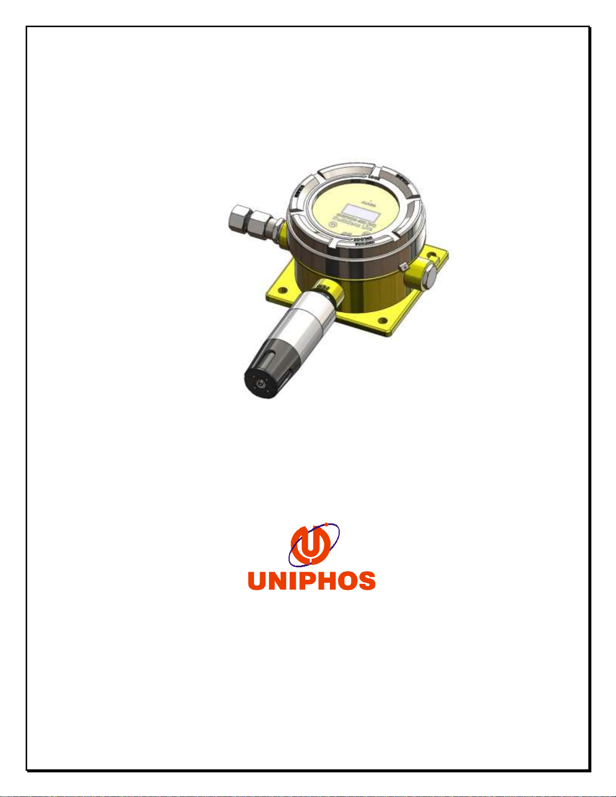
Modular design of this product helps user to have ease in
installation, operations & maintenance throughout the product life.
It has integral mounting plate consisting of four holes on the
transmitter body for easy mounting. The transmitter may be fixed
directly to a surface on the walls or similar support structure.
On activation of the power supply to the transmitter; within few
seconds it recognizes the sensor plugged into it, tests it and resume
operation.Incompatible sensors are detected by the intelligence
inside and appropriate user prompting is provided on the display.
All the transmitters are supplied pre-configured & optionally
include one alarm relays. The relay operation, alarm set points,
Date Time can be adjusted using the transmitter’s LCD/OLED and non-
intrusive magnetic switches. Outputs are automatically inhibited
during adjustments there by reducing the risk of false alarm at the
control panel during maintenance.
The transmitter unit ensures easy installation and the fastest
routine operation by removing the need for hot work permits in
hazardous areas. Using easy to replace plug-in* sensor modules,
downtime is also reduced and on-going costs are minimized.
The sensors have proven history of reliable, long term performance
and are relatively unaffected by ambient temperature & humidity
variations. Gas enters the transmitter‘s sensor by convection and
diffusion through a sintered stainless steel or wire mesh screen at
the opening of the sensor housing. The transmitter is capable of
responding to a momentary puff of gas that would otherwise remain
undetected.
The transmitter’s explosion proof design allows operation in areas
where the combustible gas concentration may exceed the lower
explosion limit (LEL). Its rugged construction ensures a long life
span in almost any environment.
The transmitter incorporates the best of both proven and new
technologies that offer versatility in addition to reliable safety
mechanism. It is most cost effective product for new and retrofit
applications.
Note: * KwikSense-Lite support smart sensor, however the
Swappability is limited only to the same Gas and its variant.

6 of 33
B. Installation
Various parts of the gas transmitter are shown in the following
diagram.
Figure 1. 500 DT Transmitter overview

7 of 33
Selecting Transmitter Location:
Select the most suitable locations for each transmitter. Several
factors should be considered when selecting location to install the
gas transmitter. The following general suggestions should be
considered.
•Air current: if there are fans, wind or other sources of air
movement, gases may tend to rise or collect in certain areas
of a facility. The local air currents should be assessed to aid
in selecting the sensor locations. Outdoor situation
considerations, such as prevailing winds, should be accounted
for. Air convection can often be more important in determining
gas concentrated areas than factors of vapor density.
•Vapor Density: When there are no air currents in the area, for
gases lighter than air we suggest placing the sensor
approximately 12” (30 cm) above the level of a potential leak
source or near the roof in indoor installation. For gases
heavier than air, we suggest placing the sensor 12”(30 cm)
below the level of a potential leak source or near the floor
or ground. Gases with density equal to air or slightly greater
than air tend to rise particularly when the air currents are
present.
•Gas emission source: as a rule, at least one sensor should be
located in close proximity to each point where leak is likely
to occur. This is particularly important when a liquid with low
volatility is being monitored.
•Environmental factors: Consider the following in selecting the
location
(i) Install sensors where they are protected from wind,
dust, snow, water, vibrations and shock.
(ii) Observe the temperate & pressure variation
surrounding the desired location. It should be within
the specified operating temperature & pressure of the
gas transmitter.

8 of 33
Mounting Guideline:
Modular design of the product simplifies the installation procedure.
The Transmitter unit has two electronic circuit boards Viz. main
processor board & relay board. Power supply & signal (4 -20 mA)
connector is located on the bottom Relay board. NO-C-NC contacts of
all the three Relays are provided on the green connectors located
on the one side of the bottom board. LCD/OLED display is plugged
on the top board & secured with screws. Certified Explosion proof
(Exd) enclosure of the unit is having provision for 3 openings for
cable entries & connections. They are to be used as following (Refer
fig.2)
•Opening on the Right hand side is equipped with 1/2” NPT/ M20
conduit fitting outlet. Use certified cable gland for cable
entry. This entry is to be used for the power supply & signal
cable connections.
•Opening on the Left hand side is equipped with 1/2” NPT/ M20
conduit fitting outlet. Use certified cable gland for cable
entry. It is to be used for the Relay cable entries.
•One opening on bottom side is occupied by the sensor housing
(sensor adaptor).
•If any one of the cable entries is not used, make sure to close
it by using certified stopper.
The transmitter may be disassembled by removing the Top Processor
board in order to get easy access to the bottom board, simplifying
the installation and field wiring.
Caution: Qualified personnel should perform the installation
according to applicable electrical codes, regulations and safety
standards. Ensure correct cabling and sealing, fitting practices
are implemented.
Install the transmitter on the predrilled mounting flange. It is
preferable to attach the transmitter to a wall or bracket, using
bolts through diagonal mounting holes, and ensure mounting is done
properly and there is no loose fitment.

9 of 33
Figure 2. Outline drawing. (Front & side views with outline
dimensions)

10 of 33
Installation:
Transmission Range: The distance that the 4-20 mA signal can travel
is dependent on several factors including the cable gauge. Maximum
cable resistance allowed is 600 ohm less the controller resistance.
Assume a constant 24 VDC power supply (at 20 Deg C), copper wire and
a controller resistance of 250 ohm. The signal range from the
controller to the transmitter takes into account the return loop.
Note: The Uniphos-500 Series Controllers have a resistance of 100
ohm maximum.
Maximum cable lengths between the controller & transmitter:
The table give below is for guidance only. Users should calculate
maximum distances using actual data for the cable being used.
Typical calculations assume minimum guaranteed controller supply of
24 VDC, minimum detector voltage of 18 VDC & maximum power supply
under full alarm.
Table: 01
Typical cable data
Maximum cable length
Cable size
(Cross section)
Cable
Resistance
Catalytic
EC
IR
Ω/km
meters
meters
meters
0.5 mm2 (20AWG)
36.8
356
478
420
1.0 mm2 (17AWG)
19.5
671
902
793
1.5 mm2 (16AWG)
12.7
1031
1384
1217
2.0 mm2 (14AWG)
10.1
1296
1741
1531
2.5 mm2 (13AWG)
8
1636
2197
1932

11 of 33
Wiring Schematic diagram:
UNIPHOS transmitter can be wired in current source mode as shown in
the below wiring schematic diagram.
Figure 3

12 of 33
4-20mA Loop Installation:
Cable Routing: Separate cables are required for each
Transmitter. In classified areas, the cable
should be in conduit or it should be an
Approved hazardous location cable
Power Supply: Ensure power supply meets the minimum
Requirements of all components of the
System. It is recommended to have a stable, clean,
regulated power supply.
Caution: Polarity must be observed. If the return & +24 Volt wires
are reversed, the transmitter will not work and may get damaged if
energized. Do not apply electrical power to the transmitter until
all connections are made, the sensor is in place and the transmitter
is completely closed.
Steps to follow: (Ref Figure-4)
Relay Cable Guideline: (Optional)
The transmitter is equipped with one potential free Relay (optional)
contacts.
Relay connections are labeled: NO (normally open), NC (normally
closed) & C (common). Attach wires as required on the field. For
wire connections, please follow the steps given below.
a. Remove the transmitter glass window cover & Top processor Board.
Top processor board is to be removed carefully & patiently as
shown in the demo video.
b. On left hand side of the Bottom board one can see three green
colored connectors viz. RLY1, RLY2 & RLY3. (Rly2 & Rly3 not
available in KwikSense-Lite version)
c. Relay Cable Installation: Attach the conduit, if applicable, pull
cable into the enclosure through the cable gland on the left hand
side of the enclosure as shown in the diagram. As per the
requirements you may take out three wires viz. NO, NC & C for each
Relay.

13 of 33
Power Supply & Signal (4-20mA) cable connections will be on the
Right hand side of processor board:
After removing the transmitter glass window cover and Top Processor
board, go for the power supply & 4-20mA signal wire connections as
given below.
Locate 3 pin Green connector CN7 on the bottom board. Pull cable
into the enclosure through the cable gland on the right hand side
of the enclosure as shown in the figure 4.
Connect 3 wires as following:
Positive Supply (+24V) : +24 VDC to the labeled terminal.
Signal (4-20mA):4-20mA loop signal to the labeled terminal
Negative Supply (AGND): Ground wire to the labeled terminal
Note: To avoid radio frequency interference (RFI), the shield
(including Mylar) must be grounded. Simply tying a bare drain wire
to ground does not ground a shield. Keep a shield as short as
possible, tie the shield to the external grounding screw. Also tie
any unused wires to the Ground.
Note:
➢3-wire connection shall be
done as below (CN7)
1. +VE (24V Dc)
2. 4-20mA (sourcing)
3. NC
4. -VE (GND)

14 of 33
Figure 4. System wiring diagram
Note:
The Armored cable Screen is to be terminated on to
the Earthing point provided on interior of the
Enclosure.

15 of 33
Settings:
The transmitter is calibrated & tested before shipping. Commonly
used parameter values are set at the factory.
Provision is made for the following settings on site
•Mute –Yes/No
This provision is given to mute the hooter. During the
calibration mode or during the routine test of the
transmitter one can select “Mute” option to mute the hooter
i.e. to disable the Relay activation.
•Alm1 –(threshold Level Value)
This is Low alarm activation level.
•Alm2 –(Short-term Threshold Level Value)
This is High alarm activation level.
•Mask –
This is factory setting. Please do not change it without
consulting with the factory.
•Relays/LED Test
This provision is given to test the Relays & alarm LED
operations site, when required.
To go into the parameter setting mode at any time, follow these
steps.
•Touch the magnetic wand on the glass window at the key “K2 “
•The transmitter display prompts for the “Password”.
(Setting Password = 0002)
•Follow the below prompt for parameter setting.

16 of 33
Table: 02 Prompts on LCD/OLED in Setting mode (Password=0002)
Sr.
No.
Display
prompts
Comment
1
Mute
XXX
To enable / disable the relay output.
XXX can be YES or NO. Key K1 is used to
change it and K2 is used to confirm the
change and go to the next prompt.
2
ALM1 =
Xxxx
To set the ALM1 of the target gas. Key
K2 is used to increment the digit where
the cursor is positioned and key K1 is
used to shift the cursor to the next
(towards left) position. After the last
digit, blinking cursor disappears,
press K2 to accept changes and go to
the next prompt.
3
ALM2 =
xxxx
In a similar fashion the set ALM2 and
move to the next prompt.
4
Tx Id=
Xx
Not Available (only for KwikSense)
5
Mask =
xx
Factory set
6
Testing
LED-RLYs
To check (activate-deactivate) the LEDs
and Relays. During this prompt, if key
K1 is pressed, it activates all the
LEDs and corresponding relays one by
one. After that if key K2 is pressed,
it comes-out from the setting mode.
Note: if the alarm condition exists, the transmitter does not allow
the user to reset a latched Low or High alarm relay.

17 of 33
Provision is made for the following settings on site
•Set Time –
This provision is given to set the Time in HH:MM:SS format.
•Set Date –
This provision is given to set the Date in DD/MM/YY format.
•Relay Selection –
This provision is given to activate / deactivate the Relays
operations site, when required.
•Oxygen Selection –
This provision is given to enable / disable the Relays &
Alarm logic for Oxygen gas.
To go into the parameter setting mode at any time, follow these
steps.
•Touch the magnetic wand on the glass window at the key “K2 “
•The transmitter display prompts for the “Password”.
(Setting Password = 0003)
•Follow the below prompt for parameter setting.

18 of 33
Table: 03 Prompts on LCD/OLED in Setting mode (Password=0003)
Sr.
No.
Display
prompts
Comment
1
Set Time
HH:MM:SS
To set the Time. Key K2 is used to
increment the digit where the cursor is
positioned and key K1 is used to shift
the cursor to the next (towards left)
position. After the last digit,
blinking cursor disappears, press K2 to
accept changes and go to the next
prompt.
2
Set Date
DD/MM/YY
To set the Date. Key K2 is used to
increment the digit where the cursor is
positioned and key K1 is used to shift
the cursor to the next (towards left)
position. After the last digit,
blinking cursor disappears, press K2 to
accept changes and go to the next
prompt.
3
RLY_SEL
xxxx
To activate / deactivate the relay
output. XXX can be HI or LO. Key K1 is
used to change it and K2 is used to
confirm the change and go to the next
prompt.
4
OXY_SEL
xxxx
To activate the relay output & alarm
logic for Oxygen gas selection. XXX can
be YES or NO. Key K1 is used to change
it and K2 is used to confirm the change
and go to the next prompt.

19 of 33
Operation
The transmitter provides continuous monitoring for the target gas.
In the event of power failure, the transmitter will automatically
reset itself back into the system loop after power is restored.
The Gas Sensor has non-volatile memory and is not be affected by
power disruptions. All programmed information is protected with
total memory retention.
At the time of power ON, the transmitter unit initializes and goes
into the warm up. Following prompts are displayed on the LCD
panel.
Table: 04Prompts on LCD/OLED during Initialization
Sr.
No.
Display
prompts
Interpretation
1
UNIPHOS
500(DT)
Model number of the product
2
KwkSense
Lite
Name of the product
3
VERSION
XX.XX.XXa
Current software version.
4
ERROR-NO
SENSOR
Error message if sensor is not connected.
5
CAL DATE
dd/mm/yy
Calibration date stored in the sensor, when
it was last time calibrated (e.g. –28/03/16)
6
XXXXXX
YYYY
Name of the target gas stored in the sensor
(e.g. O2) and gas concentration reading of
the target gas sensed by the sensor (e.g. –
20.9)
Display: The LCD/OLED displays the present target gas
concentration readings in ppm or % range. Backlight is always ON.
Note: It is recommended to calibrate the transmitter before first
time use.
Output:
The 4-20mA loop current is sent in normal conditions (from 4 to
20mA according to the calibrated values & target gas concentration
present on the site)

20 of 33
Gas Alarm conditions & Advice:
If the current gas concentration reading meets or exceeds either
alarm set points, the transmitter alarm function activates.
When the alarm condition no longer exists, the transmitter exits
alarm mode and enters normal mode operation.
The Oxygen Low and/or High gas alarm set points are user settable
for either enrichment and/or deficiency alarm as desired.
Table: 05 Alarms
Alarm
condition
Alarm Relay
Alarm LED
(Visual
Indicator)
LCD/OLED display
LOW GAS ALARM
The gas
concentration
meets or
exceeds the
low alarm set
point
If relay is
not muted,
alarm relay
triggers the
connected
device.
Visual
Indicator
(LED) turns to
blue color
Numeric LCD/OLED
display indicates
the gas
concentration
currently present
in ppm, % LEL or %
V/V.
HIGH GAS
ALARM
The gas
concentration
meets or
exceeds the
high alarm
set point
If relay is
not muted,
alarm relay
triggers the
connected
device.
Visual
Indicator
(LED) turns to
RED color
Numeric LCD/OLED
display indicates
the gas
concentration
currently present
in ppm, % LEL or %
V/V.
OVER RANGE
GAS ALARM
The gas
concentration
meets or
exceeds the
measuring
range
If relay is
not muted,
High alarm
relay remains
in activated
position.
Visual
Indicator
(LED) turns to
Red color
Numeric LCD/OLED
display indicates
“OVR“
Note: If Mute function is enabled the relay will not be activated
for alarm condition / fault condition.
Table of contents