Fly Sky FS-i6 Owner's manual

Copyright 2018, Mark Joerger
Programming the FlySky FS-i6 Transmitter for Combat Robotics
You bought a FlySky-i6 radio system because of its impressive list of features, its incredibly low price, and its
popularity with combat robot builders. It's what you call a 'no-brainer'. Then the box arrived and it contained a
transmitter, a receiver, and no manual. A quick search on the 'net and you have a FlySky manual -- half of it is in
Chinese and the other half might as well be. No problem, you head over to YouTube and soon have multiple
videos on how to setup the FS-i6... for airplanes, helicopters, and quads. What about your combat robot?
Not to worry -- I'm here to help. I'll try to avoid aircraft related names when describing the radio functions but
I'll leave them in where required to allow reference to the manual or labels on the transmitter.
There are multiple versions of the FS-i6 manual on-line. None are good, but the best is this all-English version
from the FlySky site: http://www.flysky-cn.com/download_detail/&downloadsId=4.html
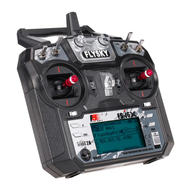
The FlySky i6X transmitter is functionally very similar to the FS-i6. There are some internal differences but almost
everything in this guide applies to the i6X as well. I've added 'i6X' notes where I have found differences.
The contents of this guide were tested and verified on a FlySky i6 running firmware version 2.0 dated 16-Aug-
2017.

Quick and Dirty Combat Set-up
You're in a hurry? Don't want any details? Grab four 'AA' cells and stuff them in the transmitter…
Throttle and rotation are on the right stick, left and right motor controllers plug into receiver ports 1 and 2, and
the stick channels all failsafe to 'off'. Test the throttle and rotation response of your drivetrain. If the response
isn't correct, step thru the ‘Troubleshooting Channel Mixing Problems’ checklist at the end of this guide.
If using channels 5 or 6: see ‘Aux Channels’ in the ‘Functions Menu Programming’ section below to assign an
appropriate switch or knob to each channel. Set the switches/knobs to ‘zero motion’ positions and return to
'Step 2' above to add failsafes to those channels.
Step 2: Set Correct Failsafe
Back at the 'MENU' screen:
•Tap the 'Down' key to highlight 'System setup' -- tap 'OK' to select.
•Use the 'Down' key to scroll down the list to 'RX Setup' -- tap 'OK' to select.
•Use the 'Down' key to scroll down the list to 'Failsafe' -- tap 'OK' to select.
•Pull the left stick all the way down, and leave the other stick axis spring centered.
•Tap 'OK' to select channel 1, tap 'Down' to turn failsafe 'On', then 'OK' to return to channel
selection. Tap 'Down' to the next channel and repeat.
•When you get to channels 5 and 6, adjust the two variable knobs (VrA, VrB) to positions
appropriate for failsafe: typically 0% for a forward/reverse ESC, -100% for an R/C switch or
unidirectional ESC. Turn failsafe 'On' and tap 'OK'.
•With all channels correctly set, press and hold 'Cancel' to exit and save the settings.
•Tap 'Cancel' three times to step back to the status display screen.
Step 1: Turn On Elevon Mixing
Flip all the toggle switches along the top of the transmitter 'up' and pull the left control stick all
the way 'down'. Push the power switch 'up'.
•Press and hold the 'OK' key 'til the 'MENU' screen appears.
•Tap the 'Down' key to highlight 'Functions setup' -- tap 'OK' to select.
•Use the 'Down' key to scroll down the list to 'Elevon' -- tap 'OK' to select.
•Tap the 'Down' key to turn Elevon 'On'.
•Use the 'OK' key to scroll to 'CH2', then the 'Up' key to set it to 100%. Leave 'CH1' at 50%.
•Press and hold 'Cancel' to exit and save the Elevon settings.
•Tap 'Cancel' to return to the 'MENU' screen.

Turning On the Transmitter
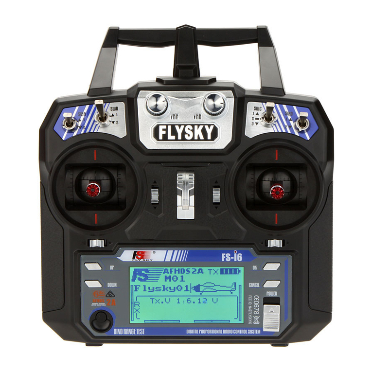
You'd think this part would be easy. Down in the lower right corner on the front of the transmitter there's a
shiny chrome slide switch with an up arrow icon labeled 'Power'. It's really tempting to slide that switch upward.
If you do, you're likely to set off a storm of alarms and cryptic alert messages. As a safety measure the
transmitter sticks and switches must be in 'safe' positions when the power is turned on to prevent unexpected
and possibly dangerous responses from your 'bot. Here's the drill:
•Flip the four toggle switches (SWA, SWB, SWC, SWD) along the top of the transmitter 'up';
•Pull the non-spring centered control stick (channel 3 'throttle') all the way 'down';
•Now you can slide the 'Power' switch 'up'.
If you try to turn it on and get a warning, you can correct the sticks and switches and it will power up; you don't
need to slide the switch back off and start over.
Menu Navigation
Menu navigation does not follow an entirely consistent method, but it starts to make sense after a while.
•At startup the transmitter display screen shows info about the currently selected 'model' (model
number, name, aircraft type, transmitter protocol) and the general state of the transmitter (battery
voltage, charge, trim tabs).
•Access the programming menus by pressing and holding the 'OK' button. Highlight either the 'System
Setup' or 'Functions Setup' with the 'Up/Down' keys and tap 'OK' to enter the selected menu. Each quick
tap on the 'Cancel' button will back you up one level thru the menu without saving any changes.
•The navigation process changes when you get to a menu screen with changeable items. On these
screens the 'OK' button will scroll downward thru the items and the 'Up/Down' buttons change the
value of the current item.
•If the screen backlight goes off, press any key to turn it back on. The menus will not accept any inputs
until the light is back on.
•A press and hold on 'Cancel' will save the changes (audible beep) and exit to the parent menu, while a
quick tap on 'Cancel' will exit without saving changes.
•Yes that's right; you hold down 'Cancel' to save your changes. You have to live with some strangeness if
you buy a cheap Chinese radio.
Warning
The transmitter does not check the positions of variable knobs VrA and VrB before
powering up. Channels 5 and 6 are assigned to those knobs by default -- do not assign weapons or
direct motion control to the FS-i6 variable knobs!

Transmitter Modes, Mixes, and Control Sticks
You have a lot of choice when it comes to how the controls for your robot are mapped to the various sticks,
switches, and knobs on the transmitter, but you need to know a little about the actual purpose for which the
transmitter was built. Twin-stick transmitters like the FS-i6 are made to control airplanes, helicopters, and
drones. If you learn a bit about aircraft terminology the manual will make much more sense.
The four axes of the dual control sticks are assigned to channels 1 thru 4 on your transmitter. These four
channels are traditionally assigned names related to the elements they control on model airplanes:
Ch 1: Aileron (Roll)
Ch 2: Elevator (Pitch)
Ch 3: Throttle (Thrust)
Ch 4: Rudder (Yaw)
Combat robots don't require pitch or roll controls, and the 'thrust' control on an airplane-style, forward-only,
non-centering control stick does not meet our need for forward/reverse drive motor control. We apply these
control functions very differently, but since we 'borrow' these radios from aircraft hobbyists we need to know
enough aircraft terminology to translate the radio manuals for our needs.
oTransmitter Modes:
There are two 'standard' ways to assign input channels to the two control sticks:
Transmitter Mode 1 is the European standard with Throttle channel 3 on the vertical axis of the right
stick, and Elevator channel 2 on the vertical axis of the left stick.
Transmitter Mode 2 is the U.S. standard which has the vertical sticks reversed: Throttle channel 3 on the
left stick and Elevator channel 2 on the right stick. The FS-i6 transmitter comes with Mode 2 enabled.
The FlySky FS-i6 allows switching between these two 'standard' modes and offers two additional modes, but
neither Mode 3 nor Mode 4 have any benefit in robot combat. See Stick Modes in the 'System Settings' section
of this guide.

oStandard Mixes
It is convenient to set-up a combat robot transmitter with one stick axis commanding both drive motors to
move forward/reverse, and another stick axis commanding the motors to move in opposite directions to turn
by 'rotation' of the robot. We are fortunate that airplane transmitters typically have that capability due to
some unusual airplane wing and tail designs that require two servos to move together to control the Elevator
function and to move opposite each other to control the Aileron or Rudder function.
•Elevon mixing (aka Delta Wing) places the robot throttle control on Elevator channel 1 and robot
rotation on Aileron channel 2.
•V-Tail mixing also places the robot throttle on Elevator channel 1, but moves robot rotation control to
Rudder channel 4.
By selecting the correct combination of transmitter mode and channel mixing type we have the option of
independently placing the throttle and rotation command axis on the left or right sticks to suit our preference.
oStick Assignments
Here is the basic setup matrix for mixes, modes, and receiver outputs to put the controls on the sticks you
want to use. Pick the control positions you want from the left columns and then implement the associated mix
and mode.
Throttle Stick
Rotation Stick
Mix Type
Mode
Receiver Ports
Right
Right
Elevon
2
1 and 2
Left
Right
Elevon
1
1 and 2
Right
Left
V-Tail
2
4 and 2
Left
Left
V-Tail
1
4 and 2
•Most builders set upinMode 2 with Elevon mixing: throttle and rotation on the right stick.
•Mode 1 will place robot throttle control on the vertical axis of the left stick, which is not spring-
centered. You can either transfer thespring-centering mechanism from one of the other axis or order
the parts needed to make all the stick axis spring centered.
•This video shows how toconvert an FS-i6 control stick to spring-centering:
https://www.youtube.com/watch?v=WxSoGHRH45k
•You can alsochange the FS-i6 firmware toallow a transmitter with channel 3centered tostartup
without setting off the safety lockout with a setting in the 'secret menu':
https://www.youtube.com/watch?v=hDRxZqklQbg&feature=youtu.be
Alternately, you might just pull down the channel 3stick atstartup.
FS-i6X Note: the 'secret menu' for the i6X has different options. Ignore the 'Sticks Adjust' function and just
turn 'Self Centering' on to allow startup with the throttle stick centered.

Functions Menu Programming
The FlySky FS-i6 and other twin-stick radios are designed to control a variety of fixed-wing and rotor-wing
aircraft. Many of the control functions available on the transmitter are of no use to combat robot applications.
The functions in this section have specific combat robot applications. They are listed in (almost) the order they
occur in the menu -- I moved a couple functions to the end for special attention.
To enter the 'Functions Menu': hold down 'OK' to open the 'MENU' screen, tap the 'Down' key to highlight
'Functions Setup', and tap 'OK'. Scroll thru the menu items with the 'Up/Down' keys, then tap 'OK' to select.
oReverse
When you push the throttle forward does your robot back up or spin in a circle? This function allows the
response of each receiver output channel to be reversed. If you spin in a circle, reverse the channel for the
motor output that is spinning backward -- if you back-up, reverse both motor output channels.
oEnd Points
Known on some other transmitters as 'Adjustable Travel Volume' (ATV) or 'Travel Adjust', this function sets the
range of response for a device plugged into a specific receiver output. Full transmitter stick input can be set to
produce anywhere between 0% and 120% of normal response at the receiver.
Response is set independently for each side of the center 'neutral' position -- move the stick/switch/knob for
the channel you're setting to the side you wish to set.
For many combat robot purposes it is more convenient to use the ‘Dual Rate’ function for this purpose, but
control functions operating on channels 3, 5, or 6 may find ‘End Points’ useful.
•Tap the 'OK' key until the desired channel is selected.
•Move the stick/switch/knob to switch between setting the high or low end of travel.
•Use the 'Up/Down' keys to increase/decrease the setting.
•Press and hold the 'CANCEL' key to save and return to the previous menu.
•Tap the 'OK' key until the desired channel is selected, then use the 'Up/Down' keys to change
setting: Nor = Normal, Rev = Reverse.
•Press and hold the 'CANCEL' key to save and return to the previous menu, or tap the “Cancel” key
to exit without saving the changes.

oDisplay
Why is this in the 'Functions' menu? 'Display' is a diagnostic tool that doesn't fit into a menu assigning control
functions. There are other diagnostics in the secret and well-hidden ‘Factory Menu’ -- maybe it should be
there? https://www.youtube.com/watch?v=hDRxZqklQbg&feature=youtu.be
'Display' pops up a graphic representation of the real-time output of signals being sent out to the receiver. It's
a very handy tool that saves a lot of time when sorting out transmitter function programming problems -- but
it's also potentially dangerous.
Holding down 'OK' in 'Display' starts 'Channel Scrub Mode' which sweeps all channels back and forth thru their
full range. This continues until you tap 'Cancel'. You don't want your 'bot to run erratically around your
workshop cycling its weapon on and off, so: Keep the 'Bot Power Off!
oAux Channels
The two control sticks use channels 1 thru 4 on the transmitter, but this is a six-channel transmitter. What
about those other two channels? The Auxiliary Channels function can assign radio channels 5 and 6 to any of
the four switches (SWA, SWB, SWC, SWD) or two variable knobs (VrA, VrB). Most versions of the FS-i6
transmitter firmware default to assigning radio channels 5 and 6 to variable knobs VrA and VrB.
•Switches SWA, SWB, and SWD are simple two-position toggles. A radio channel assigned to one of
these switches the device controlled by that channel will have two possible command states. In model
airplanes channel 5 is often assigned to a two-position toggle for the up/down actuation of retractable
landing gear, aka ‘retracts’. In a robot you might use a two-way toggle channel to turn on a hardware
'invert' function, or to turn a piezo gyro on/off.
•Switch SWC is a three-position toggle. An ESC with reverse on a channel assigned to SWC can provide
'forward/off/reverse' control of a motor. A forward-only ESC on SWC can provide 'fast/slow/off' motor
control. If a servo is on the channel you will have left/center/right control.
Move each stick/switch/knob to verify the effects of Channel Reversing, End Points, Auxiliary Channel
Positions, Dual Rates, Switch Assignments, and Mixes.

•Variable knobs VrA and VrB provide continuous range control to a channel assigned to them, like a
stick axis. In model airplanes channel 6 is often assigned to the control of Flaps which modify the lift
properties of the wing at slow flight speeds. See the warning about assigning robot weapon control to
the FS-i6 knobs in the ‘Turning On the Transmitter’ section of this guide.
FS-i6X Note The FS-i6X has an extra function in its 'System Menu' called 'Aux Switches' that can activate and
deactivate individual switches and knobs. If you have a FS-i6X and you do not see all of the switches and knobs
that should be available to you in the 'Aux Channels' functions, check the 'Aux Switches' function to make sure
they are all activated.
oSubtrim
The trim buttons by the sticks on the transmitter adjust the center position of each stick axis. If multiple
output channels are ‘mixed’ on that stick axis they will all be affected. ‘Subtrim’ lets us adjust the center
positions of individual receiver outputs. Two motor controllers mixed to a single transmitter stick axis can be
individually adjusted so that both motors power up together at slow speed rather than one motor turning on
first resulting in a very slow turn instead of a slow forward crawl.
To set subtrims: prop the drive wheels off the ground and push the throttle forward slowly 'til one motor just
starts to turn. Select the receiver channel port the other motor is plugged into and slowly increase the
'Subtrim' setting 'til both motors turn.
•Tap the 'OK' key until the desired channel is selected.
•Use the 'Up/Down' keys to change the subtrim position.
•Holding the 'OK' key down for 2 seconds will zero all subtrims.
•Press and hold the 'CANCEL' key to save and return to the previous menu, or tap the 'CANCEL' key
to exit without saving the changes.
•Tap the 'OK' to change between channels 5 and 6.
•Use the 'Up/Down' keys to select a specific switch or knob. Select 'None' to deactivate all controls
for that channel.
•Press and hold the 'CANCEL' key to save and return to the previous menu.

oDual Rate/Exp
'Dual Rate' and 'Exponential Response' are typically addressed separately in transmitter function settings, but
FlySky has opted to combine them into a single setting. Both functions are switched between their two
settings the same time by switch SWA.
These functions can only be applied to stick channels 1, 2, and 4 -- but channel 3 has its own switchable
functions: see 'Throttle Curve' and 'Throttle Hold' at the end of this functions setup section.
Dual Rate offers a switchable reduction or increase in the influence that movement of a specific transmitter
stick has on receiver output, effectively limiting the response of the stick. For a combat robot a dual rate is
commonly used to adjust 'Rotation' sensitivity. A robot with a full-range response on the 'Rotation' channel
can be difficult to control in the ‘heat of battle’ – overcorrecting and zigzagging across the arena. Setting a
dual rate on the 'Rotation' channel can keep your ‘bot composed under normal conditions and still allow a full-
rate 'righting spin' or 'victory dance' at the flip of a switch.
•Try setting up your Elevon or V-Tail mix with both channels at 100%. Then set a dual rate on the
‘Rotation’ channel (Ch 1 for Elevon, Ch 4 for V-Tail) to 50% ‘Normal’ and 100% ‘Sport’. This gives good
rotation control under normal operation, but allows a high spin rate for special conditions at a flick of
switch 'SWA'.
Exponential Response affects fine-level control, but in a different way than dual rate. Entering negative
values here will reduce the sensitivity of the control stick near the center of stick motion to allow for fine
control, but increase sensitivity as stick motion approaches the limit of travel to ‘squeeze in’ full response
range. Useful on the 'Rotation' channel, you may also like a little 'expo' on the robot throttle channel to give
more precise low speed control.
•Start with 'Rotation' and 'Throttle' (channels 1 and 2 on an Elevon mix) set to minus 50% for 'normal' /
0% sport.
•Tap the 'Up/Down' keys to select the desired channel.
•Flip switch 'SWA' up to set 'normal' response settings.
•Tap 'OK' to change between setting types.
•Use the 'Up/Down' keys to change the selected setting.
•When all settings are in place for 'normal' response, flip 'SWA' down to enter 'sport' response
settings.
•Press and hold the 'CANCEL' key to save and return to the previous menu, or tap the 'Cancel' key
to exit without saving the changes

oMix
In R/C aircraft it's common for a change in one control to have an undesired effect on stability that must be
countered by a second control. For example, actuating Flaps may require a change in Elevator to keep the
plane level. The 'Mix' function allows you to program a custom response in a 'slave' channel whenever the
'master' channel actuates to offset these undesired effects. You may have up to three of these custom mixes.
•The preset 'Elevon' and 'V Tail' mixes (below) are all you need to setup single-stick control of your
differential drive motors. The custom mixes can be saved for other uses.
•The FS-i6 does not allow custom mixes to be assigned to a transmitter switch to turn them on/off in
combat; they must be turned on/off from within the menu system. This severely limits their use in
combat robot control. For example, they cannot be used to create a 'invert switch' that corrects the
reversal of the forward/reverse stick axis when the robot is flipped upside-down.
oElevon
'Elevon' is the standard channel mix for single-stick combat robot control. In the default 'Transmitter Mode 2',
Elevon mixing places both throttle and rotation control on the right-hand stick, leaving the left stick open for
other uses.
Vertical stick axis #2 Elevator commands both speed controllers in the same direction for forward/reverse
motion, while horizontal stick axis #1 Aileron commands the speed controllers in opposite directions for
left/right rotation. Left and right side speed controllers plug into receiver ports 1 and 2.
Change both ‘percentage’ settings to 100%; that will be too much rotation authority for stick #1, but we will
correct that with a ‘Dual Rate’. If not using a dual rate, leave channel 1 at the default 50% and set channel 2 at
100%.
•Use the 'Up/Down' keys to turn the function on/off.
•Tap the 'OK' key to move down thru the percentage settings.
•The 'Up/Down' keys change the selected percentage setting.
•Press and hold the 'CANCEL' key to save and return to the previous menu, or tap the 'Cancel' key
to exit without saving the changes.

oV-Tail
V-tail is used less frequently than Elevon as a combat robot drive mix. It moves the rotation control axis from
the generally preferred right stick Aileron location to the left stick Rudder location. Right and left side speed
controllers plug into receiver ports 4 and 2. Setup is the same as the Elevon mix.
oSwitches Assign
The 'Switches Assign' function controls which switches control 'Fly Mode', 'Idle Mode', and 'Throttle Hold'
selection.
Fly Mode Switch On many radios this is called the 'Dual Rate Switch' because it controls which 'Dual Rate' is
active. Switch SWA is the default assignment.
Idle Mode Switch A flip of this switch selects which of the two throttle response profiles available in the
Throttle Curve function is active (see next page). The effect is similar to the 'Dual Rate/Exp' function available
on other stick channels. Switch SWB is the default assignment.
Throttle Hold Switch If the 'Throttle Hold' function (see below) is activated, a flip of this switch will cause the
transmitter to ignore the position of the channel 3 stick axis and set the channel 3 output to a specified
percentage. Switch SWD is the default assignment.
I moved the ‘Throttle Curve’ and ‘Throttle Hold’ functions out of menu-order and put them here at the
end of the section because it makes sense to discuss them after the ‘Switches Assign’ function.
•Tap the 'OK' key to step between the three assignable controls.
•Use the 'Up/Down' keys to change the switch assignment.
•Press and hold the 'CANCEL' key to save and return to the previous menu, or tap the 'CANCEL' key
to exit without saving the changes.

oThrottle Curve
This function adjusts the response of channel 3 to compensate for non-linear engine responses in 'gas'
engines. It is similar to the 'Dual Rate/Exp' function for the other stick channels but a more elaborate response
curve can be defined by setting response at five stick points: 0%, 25%, 50%, 75%, and 100%.
It has two modes controlled by SWB: 'Normal' and 'Idle Up' that are set independently -- like the dual rate. I
can't think of any use for this function on a combat robot unless you're running an internal combustion engine
on your weapon.
oThrottle Hold
This function will lock channel 3 to a fixed percentage output and ignore the position of the stick. In a combat
robot this is commonly used as a safety 'lock out' for a spinner weapon. It works like this:
•The 'power on' safety system will not allow the transmitter to become active unless all four toggle
switches are in the 'up' position and the channel 3 stick is all the way down.
•Once the transmitter has power, the channel 3 stick is held inactive by the 'Throttle Hold' switch SWD
being in the 'Not Engaged' up position.
•The channel 3 stick will remain inactive until SWD is switched down to release the throttle hold.
•Flip the 'Throttle Hold' switch up to enter 'Not Engaged' mode.
•Tap 'Up/Down' to turn 'Hold' on.
•Tap 'OK' to select the 'Value' setting.
•Hold 'Down' to set 'Value' to 0%.
•Flip the 'Throttle Hold' switch down to verify that 'Hold' is off in the 'Engaged' setting.
•Press and hold the 'CANCEL' key to save and return to the previous menu.
•Flip the 'Idle Mode' switch (default SWB) up to enter the 'Normal' response curve.
•Tap 'OK' to select the curve point to change.
•Use the 'Up/Down' keys to change the point position.
•Press and hold the 'OK' key to return all points to default settings.
•When finished setting 'normal' response, flip 'SWB' down to set the 'Idle Up' curve points.
•Press and hold the 'CANCEL' key to save and return to the previous menu, or tap the 'Cancel' key
to exit without saving the changes.

System Settings Menu
Some minor functions important to combat robot control preference are hidden away in the 'System Settings'
menu even though they apply to the specific robot being controlled rather than the transmitter system itself.
To enter the 'System Settings Menu': hold down 'OK' to open the 'MENU' screen, tap 'Up/Down' to highlight
'System Setup', and tap 'OK'. Scroll thru the menu items with the 'Up/Down' keys, then tap 'OK' to select.
oModel Setup Functions
This group of functions allows you to save up to 20 sets of function/system settings and quickly switch
between them to control different robots. If you have only one robot you can ignore this section. The manual
is accurate and complete for these functions, and the commands are intuitive -- I won't duplicate the
instructions. Here's an overview:
Model Name
Now that you have the transmitter functions set up for your first robot, this
function will assign a name to that set of functions so you can spot recognize it in
the list of saved function sets.
Type Select
The FS-i6 is made to control airplanes and a variety of helicopter styles. The
helicopter types are very specific to helicopter functions and are of no use to
combat robots. Stick with the default 'Airplane or Glider' type.
Model Select
When you're ready to start setting functions for a new robot you will need to
select an unused model to avoid overwriting the functions you set for the prior
robot. When you want to use a saved model, this is where you find it.
Model Copy
Is the new set of functions you're going to set-up similar to an existing model you
already have? Save some time and 'Copy' that existing model into the new
unused model you just selected and save a lot of time.
Model Reset
Do you have a saved model you no longer need? This function will reset all the
functions and clear the name. You will be prompted to confirm the reset.
oSticks Mode
The function maps transmitter channels 1 thru 4 to the control stick axis. See the section on 'Transmitter
Modes, Mixes, and Control Sticks' for factors to consider in selecting stick axis locations.

Receiver Setup Submenu
Hidden down near the bottom of the 'System Settings Menu' is a 'RX Setup' option that opens a new submenu.
Most of the functions included in this sub-menu apply only if you're adding receivers that use a different
protocol or setting up telemetry sensors. There is only one programming function hidden in here, but it's an
important one. The 'Failsafe' function determines how your robot will respond when the transmitter signal is
lost.
oFailsafe
The default failsafe 'Off' setting will lock the selected channel on any of the 'A series' receivers (A6, iA6, iA6b...)
in the last setting it had before the transmitter signal was lost. That is not an acceptable response for a combat
robot!
Turning failsafe 'On' will return a receiver port to a pre-selected safe setting that will bring all motion on the
robot to a stop -- a correct failsafe response.
Not using one of the 'A-series' receivers? Check your receiver docs for their failsafe info.
•Use the 'Up/Down' keys to navigate to the 'System setup' screen -- tap 'OK' to select.
•In the 'System Setup' menu, 'Up/Down' to scroll to 'Receiver Setup' -- tap 'OK' to select.
•'Up/Down' to scroll down the list to 'Failsafe' -- tap 'OK' to select
•Pull the left stick all the way down, and leave the other stick axis spring centered.
•Tap 'OK' to select channel 1, 'Up/Down' to turn failsafe 'On', then 'OK' to return to channel
selection. 'Up/Down' to the next channel and repeat.
•When you get to channels 5 and 6, adjust the two variable knobs (VrA, VrB) to positions
appropriate for failsafe before turning failsafe on and tapping 'OK'. That's typically 0% for a
forward/reverse ESC, -100% for an R/C switch or a unidirectional ESC.
•When all channels are correctly set, press and hold 'Cancel' to exit and save the Elevon settings.
•Tap 'Cancel' three times to step back to the status display screen.

Troubleshooting Channel Mixing Problems
Having your channel mixing setup correctly on your transmitter gets the right signals sent to your receiver, but
that doesn't mean that your robot is going to respond correctly to the stick inputs. The left and right side
motor controllers may be plugged into the wrong receiver ports, the current polarity to the motors may be
reversed, and you may even have accidentally activated a mixing option in the controller board that is
competing with your transmitter mixing.
Step thru the list of symptoms below and correct each problem you find. You'll be up and running quickly.
http://runamok.tech
Given a forward command, only one motor responds -- given a right turn command, only the
other motor responds.
•You have either all mixing turned off, or both transmitter mixing and speed controller mixing
turned on. Adjust so one and only one mix source is active.
Given forward command, robot backs up straight.
•Use the transmitter Reverse function on both of the channels that feed your motor controllers.
Given forward command, robot spins in place.
•Use the transmitter Reverse function on the channel that feeds the controller for the motor that
is backing up.
Given right turn command, robot turns left, and vice versa.
•Swap the receiver plugs for the two channels that control the motor controller(s). If you are
using channels 1 and 2, unplug the receiver connectors and plug the connector that was in
channel 1 into channel 2 and vice versa. You may have to correct the servo reversing for the two
channels after doing this to get correct forward/reverse motion, but the turning control will be
correct when you're done.
Other manuals for FS-i6
4
Table of contents
Other Fly Sky Transmitter manuals
Popular Transmitter manuals by other brands
PR electronics
PR electronics 5350 manual
Nautel
Nautel J1000 Installation and operation manual

Azbil
Azbil ATT082 Functional safety manual

Gatekeeper Systems
Gatekeeper Systems Long Range Transmitter 2 user manual
Xylem
Xylem MJK Oxix Installation and user manual

AssetScan
AssetScan ASM01 Hardware Setup Instructions
