Fly Sky FS-G7P User manual

FS-G7P
User Manual
New ANT(Ant protocol)Automatic
Frequency Hopping Digital System
Copyright ©2022 Flysky Technology Co., Ltd

Thank you for purchasing our products.
Read the manual carefully to ensure your personal safety as well as the
safety of your equipment.
If you encounter any problems during using, please refer to this manual
first. If the problem is still not resolved, please contact the local dealer
directly or contact the customer service staff via the website below:
http://www.flysky-cn.com

1. Safety..................................................................................................................1
1.1 Safety Symbols .....................................................................................................................................................1
1.2 Safety Guide...........................................................................................................................................................1
2. Product Introduction.......................................................................................2
2.1 Transmitter Overview ...........................................................................................................................................2
2.2 Receiver Overview .................................................................................................................................................3
2.2.1 Status LED...........................................................................................................................................................3
2.2.2 Interface...............................................................................................................................................................3
2.3Antenna ..........................................................................................................................................................3
3. Preparation .........................................................................................................4
3.1 Installing Transmitter Battery.................................................................................................................................4
3.2 Installing Receiver and Servo..................................................................................................................................4
4. Operation guide....................................................................................................5
4.1 Power-on.................................................................................................................................................................5
4.2 Bind.......................................................................................................................................................................5
4.3 Setting Transmitter LED and Audio....................................................................................................................5
4.4 Calibration.........................................................................................................................................................6
4.5 Restoring Factory Settings.................................................................................................................................6
4.6 Power-o.................................................................................................................................................................6
5. System Interface...................................................................................................7
6. Function Menu......................................................................................................8
6.1 Settings-Channel Reverse ......................................................................................................................................9
6.2 Settings-Servo Travel..............................................................................................................................................9
6.3 Settings-Neutral Trim...........................................................................................................................................10
6.4 Settings-Dual Rate...................................................................................................................................10
6.5 Settings-Curve.......................................................................................................................................................11
6.6Settings-Smart Vehicle Control (SVC)............................................................................................................11
6.7 Settings-Beginner Mode.......................................................................................................................................11
6.8 Auxiliary Channels-CH3 to CH7............................................................................................................................12
6.9 Mixes ....................................................................................................................................................................12
6.10 Mixes-Steering Mixes...........................................................................................................................................12
6.11 Mixies-Programming Mixes...............................................................................................................................13
6.12 Timer..........................................................................................................................................................13
6.13 Timer-Timer..............................................................................................................................................13
6.14 Timer-Lap List............................................................................................................................................13
6.15 Switch Assignment..............................................................................................................................................14
6.16 Receiver Settings.................................................................................................................................................14
6.17 Receiver Settings-Failsafe...................................................................................................................................14
6.18 Receiver Settings-Bind Settings.........................................................................................................................15
6.19 Receiver Settings-Range Test.............................................................................................................................16
6.20 Receiver Settings-Sensor....................................................................................................................................16
6.21 Receiver Settings-ESC Settings..........................................................................................................................16
6.22Receiver Settings-i-BUS Settings FS-CEV04...................................................................................................17
6.23 Model ..................................................................................................................................................................17
Contents

6.24 System Settings...................................................................................................................................................18
6.25 System Settings-System Settings.......................................................................................................................18
6.26 System Settings-Stick Calibration......................................................................................................................19
6.27 System Settings-Firmware Update....................................................................................................................19
6.28 System Settings-Factory Reset...........................................................................................................................20
6.29 System Settings-Help Center..............................................................................................................................20
6.30 System Settings-About.......................................................................................................................................20
7. FS-R7P Function Instructions...............................................................................21
7.1 Attentions ..............................................................................................................................................................21
7.2 Binding...................................................................................................................................................................21
7.3 Firmware update...................................................................................................................................................21
7.4 Failsafe.................................................................................................................................................................22
8. Product Specications.......................................................................................23
8.1 Transmitter Specication FS-G7P ........................................................................................................................23
8.2 Receiver Specication FS-R7P ...........................................................................................................................24
9. Packing List.......................................................................................................25
10. Certication.....................................................................................................26
10.1 DoC Declaration ..................................................................................................................................................26
10.2 CE Warning ..........................................................................................................................................................26
10.3 Appendix 1 FCC Statement ...............................................................................................................................26
11. Environmentally friendly disposal..................................................................27
1
• Misuse of this product may lead to serious injury or death. To ensure the safety of you
and your equipment, read this manual and follow the instructions.
• Make sure the product is properly installed in your model. Failure to do so may result in
serious injury.
• Make sure to disconnect the receiver battery before turning o the transmitter. Failure
to do so may lead to unintended operation and cause an accident.
• Ensurethatallmotorsoperateinthecorrectdirection.Ifnot,adjustthedirection
first.
• Makesurethemodelstayswithinthesystemsmaximumrangetopreventlossof
control.
• Do not use the product at night or in bad weather like rain or thunderstorm. It can
cause erratic operation or loss of control.
• Do not use the product when visibility is limited.
• Do not use the product on rain or snow days. Any exposure to moisture (water or snow)
may cause erratic operation or loss of control.
• Interference may cause loss of control. To ensure the safety of you and others, do not
operate in the following places:
• Near any site where other radio control activity may occur
• Near power lines or communication broadcasting antennas
• Near people or roads
• On any body of water when passenger boats are present
• Do not use this product when you are tired, uncomfortable, or under the inuence of
alcohol or drugs. Doing so may cause serious injury to yourself or others.
• The 2.4GHz radio band is limited to line of sight. Always keep your model in sight as a
large object can block the RF signal and lead to loss of control.
• Do not touch any part of the model that may generate heat during operation, or
immediately after use. The engine, motor or speed control, may be very hot and can
cause serious burns.
Prohibited Mandatory
1.Safety
1.1 Safety Symbols
Pay close attention to the following symbols and their meanings. Failure to follow these warnings could cause damage,
injury or death.
1.2SafetyGuide
Warning • Not following these instructions may lead to major injuries.
Danger • Not following these instructions may lead to serious injuries or death.
Attention • Not following these instructions may lead to minor injuries.

FS-G7P
Digital Proportional Radio Control System
2
2.Product Introduction
This product uses the 2.4 GHz New ANT(Ant protocol) enhanced automatic frequency
hopping digital system, consisting of FS-G7P transmitter and FS-R7P receiver. It has an output of
7 channels, compatible with model cars, boats, etc.
2.1 Transmitter Overview
Firmware upgrade, USB emulator,
and system power supply
Fixed port for the holder
of a mobile phone
for power supply
through 2s lithium
battery
[1]
[6]
[7]
[2] [3] [4]
[5]
[17]
[15]
[16]
Display
SW1 Key VR1 Knob
Ambient LED
Five-way switch, and keys for
menu navigation operations
RETNEthgiR
KCABtfeL
toggle switch
[11]
[12]
[8]
[9]
[10]
Power supply switch
[13]
[14]
compatible with the plac
ement
of lithium batteries.

3
2.2 Receiver Overview
2.2.1 Status LED
The status LED indicates the power supply state of the receiver and its working state.
Off: The receiver is not powered on.
Light on in red: The receiver is connected to the power supply. It works normally.
Fast flashing: The receiver is in the bind mode.
Slow flashing: The LED flashes slowly when the receiver is powered off, unbound, or no signal.
2.2.2 Interface
All the interfaces are 2.54 mm standard pins for connecting the receiver to each terminal part of
the model. Please follow the direction according to the label see the label direction on the side
of the receiver.
2.3 Antenna
Note
• To ensure the signal quality, the transmitter and receiver antennas should be kept
vertical to the ground as much as possible. In operations, please adjust the transmitter
angle. Make the antenna towards the direction of the model receiver. Keep the receiver
antenna extending out of the model and perpendicular to the ground.
Caution
• It is strictly prohibited to hold the antenna of the transmitter and the antenna of the
receiver in operations. Otherwise, the quality and strength of the radio transmission
signal will be greatly reduced, resulting in the failure and out of control of the model.
Note
• Do not pull the antenna of the receiver. Do not tie the antenna and the servo cable
together. Do not put the antenna close to the metal materials, because this will aect
the signal strength of the receiver.
It should be noted that this is a transmitter with a built-in antenna. Please use the transmitter
correctly.
[1]
[2]
[3]
[4]
[5]
[6]
[7]
[8][9][10]
[11]
[12] [13] [14]
[16]
[17]
[15]
[1] CH1/P(PWM/PPM)
[2]-[5] CH2- CH5
[6] BIND interface
[7] BVD/VCC(Battery voltage detection/Power supply interface)
[8] CH7
[9] SERVO
[10] LED
[11] Antenna
[12] BIND button
[13] SENS interface
[14] CH6
[15] Signal pin
[16] + (Power anode)
[17] - (Power cathode)
FS-G7P
Digital Proportional Radio Control System
4
Danger • Do not use the battery if damaged
Battery type: AA batteries or 2S lithium batteries JST interface inside the battery compartment.
Please follow the steps below to install the transmitter batteries:
1. Open the battery compartment cover.
2. Put 4 AA batteries with sufficient electricity into the battery compartment. Ensure that the
metal terminals on the batteries contact the metal terminals inside the battery compartment.
You should choose the proper size of 2S 7.4V lithium battery to access the JST interface.
Connect them correctly.
3. Cover the battery compartment.
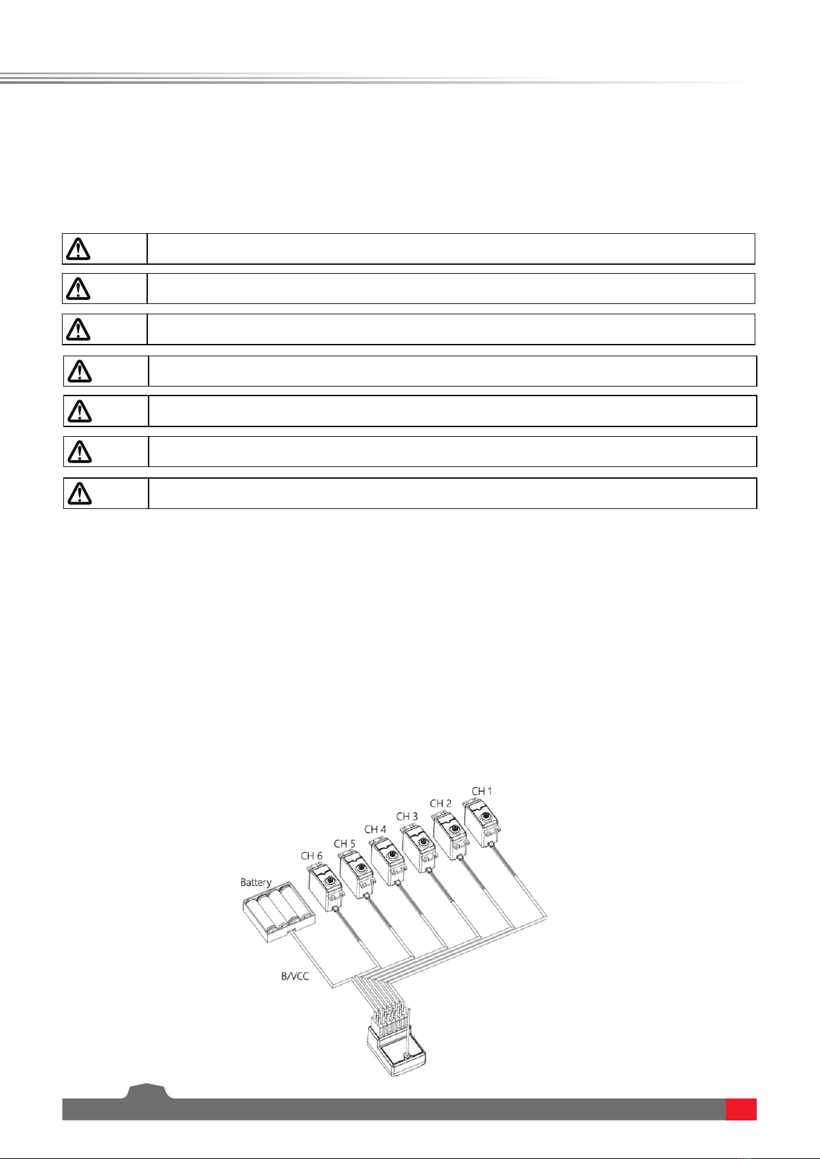
3.2 Installing Receiver and Servo
Install the receiver and servo in the following methods:
3. Preparation
Prior to operations, please install the battery and connect devices according to the
sequence and guide as described in this chapter.
3.1 Installing Transmitter Battery
Danger • Do not open, disassemble, or attempt to repair the battery.
Danger • Only use specied battery (X4 AA batteries).
Danger • Do not crush/puncture the battery, or short the external contacts.
Danger • Do not drop the battery or expose to strong shocks or vibrations.
Danger • Do not expose to excessive heat or liquids
Danger • Always store the battery in a cool, dry place.

5
4. Operation guide
After the preparation is completed, you can start to use the product according to the guide
in this chapter.
4.1 Power-on
Power on the product according to the following steps:
1. Check the system status to make sure the battery is fully charged and properly installed.
2. Turn the switch to the [On] position. The screen will light up.
3. Power on the receiver.
Warning • At this point, the system starts. Please operate carefully. Otherwise, it may cause
damage to the product or injury to people.
Warning • For your safety, please turn the transmitter switch and throttle to the safe position.
4.2 Bind
The ex-factory bind settings of the transmitter and receiver are completed successfully.
If you need to replace the transmitter or receiver with another one, please follow the steps below
for binding:
1. Connect the power cable to the VCC/BVD interface on the receiver. At this time, the receiver
indicator flashes slowly;
2. Press and hold the BIND key on the receiver for more than 3 seconds or press and hold the
BIND key on the receiver for power-on.
3. Power on the transmitter and set the receiver. In the BIND SET, select the BIND: START. At this
time, the system is in bind mode.
4. After the bind is successful, the receiver LED is always on, and the transmitter automatically
exits the bind state;
5. After the bind is completed, you can use it normally.
4.3 Setting Transmitter LED and Audio
This LED is a monochromatic light. You can set the ON and OFF state. You can enable or disable
the audio for the system operations and alarms. For system operations and alarms, you can
enable/disable the audio separately or collectively. In addition, you can set the audio volume
• The procedure is applicable to the bind between only FS-G7P transmitter and FS-R7P
receiver. The bind methods vary with receivers. For details about the operations, you can
visit the FLYSKY official website to obtain the receiver manual or other related information.
• Since the product is constantly updated, please visit the FLYSKY official website to obtain the
latest transmitter and receiver compatibility list.
This product system is compatible with most of our ANT Protocol receiver models. The details are
as follows:
RF standard: 2.4 GHz Ant protocol
Receiver model: FS-R7P

FS-G7P
Digital Proportional Radio Control System
6
4.4 Calibration
The calibration is required in case of data offset of the transmitter due to physical wear in long-
term operations. At this time, we need to calibrate the output data and neutral angle of the
traversing handwheel, throttle trigger, and VR2.
The transmitter has been calibrated at the factory. If you need to recalibrate it, please follow the
steps below: Please follow the steps below to perform the settings:
1. Power on the transmitter, enter the system menu, and select the stick calibration function.
Follow the prompts to press the Start key for calibration.
2. Swing the handwheel and trigger to the maximum and minimum travel in each direction
respectively and then release them. Toggle the VR2 left and right repeatedly to the maximum
extent for two or three times. Finally, toggle the VR2 back to the middle position.
3. Press the return key to exit the calibration interface. The calibration is complete. If the pop-
up window indicates that the calibration has failed, it means that the control to be calibrated
has not reached the maximum and minimum travel, or VR2 has not been toggled to the middle
position. The re-calibration is required.
4.5 Restoring Factory Settings
When you want to clear the data in the transmitter, you can restore all data in the transmitter to
default values. That is, all model data and settings are restored to the default state.
Please follow the steps below to restore factory settings:
1. Power on the transmitter, enter the system menu, and select the factory reset function. Follow
the prompts to press the OK button to start the reset.
2. After the successful reset, the system automatically returns and stays in the system menu
interface. It indicates that the system has been restored to the factory settings.
4.6 Power-o
Please follow the steps below to power off the system:
1. Power off the receiver.
2. Turn the switch to the [OFF] position to turn off the transmitter.
Caution • When you shut down the system, make sure to power off the receiver, and then the
transmitter. Otherwise, the model may be damaged and people may be injured.
separately.
Please follow the steps below to perform the settings:
1. Start the transmitter and enter the SYSTEM menu. In the SYSTEM settings, set the LED, SOUND,
and VOLUME.
2. After the settings are completed, return back.
7
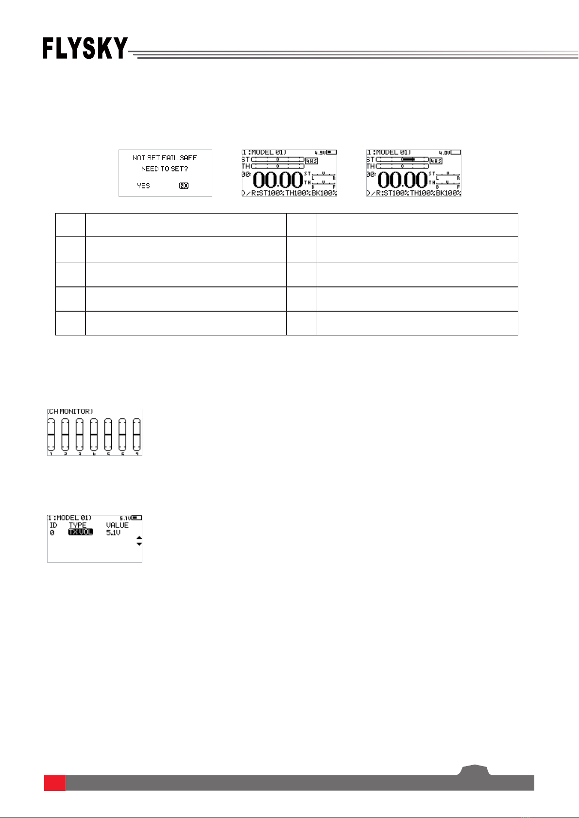
5. System Interface
[1] Model name and number [6] Signal and strength
[2] Steering channel(ST) output display [7] Transmitter voltage and display
[3] Throttle channel(TH) output display [8] Direction trim display
[4] Timer [9] Throttle trim display
[5] DR output display
Main system interface
Enter the main system interface after power-on.
Sub-page 1
After power-on, enter the main system interface and press the UP key. Press the return key to
return to the main system interface.
Sub-page 2
After power-on, enter the main system interface and press the DOWN key. Press the return
key to return to the main system interface.

FS-G7P
Digital Proportional Radio Control System
8
6. Function Menu
Function description:
In this transmitter, we have classified the functions and made a new layout. There are 8
categories in icons in total. That is: Setup(SET), Auxiliary Channel(AUX.CH), MIXES, TIMER, Switch
Assignment(SW ASSIGN), Receiver Settings(RX SET), MODEL, System Setup(SYSTEM SET). After the
classification, it will become more convenient and easy to set up the model.
SET
AUX.CH
MIXES
TIMER
SW ASSIGN
RX SET

9
MODEL
SYSTEM SET
Function operations:
In the main interface, press the OK key to enter the function menu. Select the function category
by pressing the UP/DOWN key. Press the OK key to enter the corresponding next-level menu.
6.1 Settings-Channel Reverse:
Function: Perform the reverse processing of the output data of one channel or more channels.
This function is used in debugging the model.
Application: When the model is designed, there may be no way to determine the unified standard.
When we assemble and debug a model, we find that the operation model is reversed to our
requirement. For example, the model moves left when we want it to move right. At this time, the
transmitter signal output needs to be adjusted. The channel reverse function is used to adjust the
action direction of each servo or motor and output signals.
Function settings:
1. In the SET menu, select the REV(channel reverse) function and press the OK key to enter
2. Select the channel you need to adjust by the pressing UP/DOWN key. Press the OK key to enter
the edit state. Then adjust it by the pressing UP/DOWN key. Press return after adjustment.
3. Test the function to confirm all the servo or motor action direction is the same as the actually
expected direction.
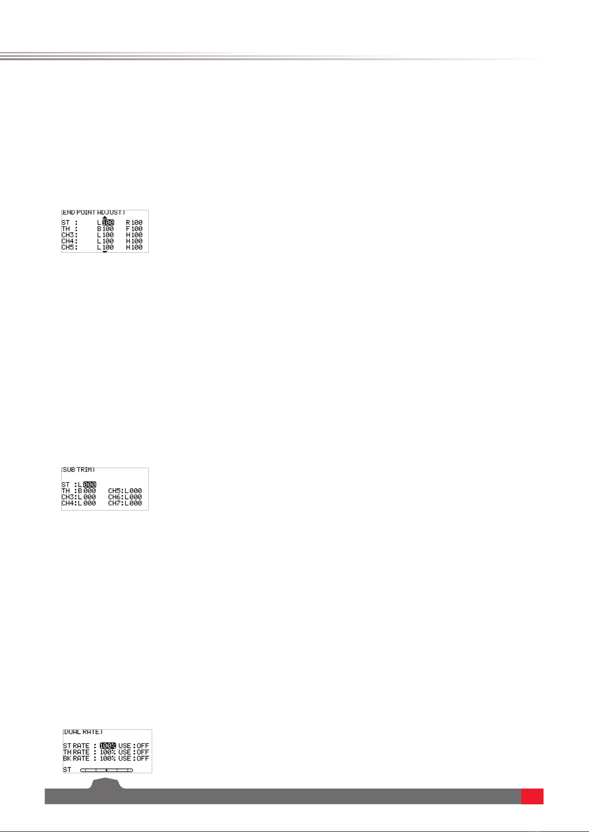
6.2 Settings-Servo Travel:
Function: Adjust the travel amount of the servo output. This function is used in debug. This
function can be used to set the travel of the left and right up/down/H/L at both ends of the
channel respectively.
When the model is designed, there are changes in the size of the structure and the specification
may not be unified. In addition, there may be different sizes of operator's habitual actions. The
servo travel function can be used to set the travel amount required for each channel to adjust the
FS-G7P
Digital Proportional Radio Control System
10
6.3 Settings-Neutral Trim:
Function: Set and adjust the neutral data of each channel.
This function is mainly used for the trim of the model in assembly and debugging. For example,
the vehicle is stationary and the transmitter traversing handwheel is in the neutral position; if
you find that the wheels deviate from the straight direction, it can be easily corrected through
this function. At this time, it is difficult and inconvenient to adjust the model structure.
Note: Before setting this function, make sure that the channel is moving in the correct direction.
Function settings:
1. In the SET menu, select the SUB TR(neutral trim) function and press the OK key.
2. Select the channel you need to adjust by the pressing UP/DOWN key. Press the OK key to enter
the edit state. Then adjust it by the pressing UP/DOWN key. Press return after adjustment.
3. Observe and test the function to ensure that the settings work as expected.
6.4 Settings-Dual Rate:
Dual rate allows you to quickly adjust the output value of certain channels to achieve the best
manipulation effect. The rate function can be used to set the direction channel channel 1,
throttle channel channel 2 upper, brake channel 2 lower channel, and output data rate. The range
is 0-100%. You can also set the switch-on and switch-off. The two control modes can be switched
through the application switch setting, see the Key Setting menu.
Function settings:
1. In the SET menu, select the D/R(Dual rate) function and press the OK key.
2. Select the channel you need to adjust by the pressing UP/DOWN key. Press the OK key to enter
the edit state. Then adjust it by the pressing UP/DOWN key. Press return after adjustment.
In the adjustment, observe by operating the corresponding channel handwheel and throttle
trigger.
3. Verify the function to confirm that all channel outputs operate normally as expected.
corresponding structure for the best match, to obtain the required operation effect. For example:
You want to operate that the turning action is not so large, you can adjust the value of the
direction channel at both ends to be smaller. In this way, the turning action should be smaller,
with less likely to be tailspin.
Function settings:
1. In the SET menu, select the EPA(servo travel) function and press the OK key.
2. Select the channel you need to adjust by the pressing UP/DOWN key. Press the OK key to enter
the edit state. Then adjust it by the pressing UP/DOWN key. Press return after adjustment.
3. Test the function to confirm all the servo or motor action directions are the same as the
actual expected travels.

11
6.5 Settings-Curve:
Curve function is used to set the output data curve adjustment of the direction channel channel 1,
throttle channel channel 2 upper, and brake channel 2 lower channel. The range is -100 to +100.It
can change the output sensitivity of each channel. When the data is bigger, the sensitivity of the
middle position is bigger and the two end positions are smaller. It is vice versa when the data is
smaller.
Function settings:
1. In the SET menu, select the CURVE function and press the OK key.
2. Select the channel to be adjusted by pressing the UP/DOWN key. Press the OK key to enter the
edit state. Select the EXP by pressing the UP/DOWN key and press the OK key. Then press UP/
DOWN key to adjust the data. After adjustment, press the return key. If you need to enable this
function, select the application item by pressing the UP/DOWN key, and press the OK key to
enter the edit state. Press UP/DOWN key to switch on. Then press the return key.
3. Test the function to confirm that the adjusted channel output operates normally as expected.
The Smart Vehicle Control function is used to set the receiver with the SVC function. The current
FS-R7P does not have the SVC function.
6.6 Settings-Smart Vehicle Control (SVC):
The beginner mode function is used to set the output limit of direction channel and throttle
channel. After this function is enabled, the channel output is only 50%. In this way, the beginner
can easily drive the vehicle under the condition of limiting the speed and turning angle.
Function settings:
1. In the SET menu, select the BEGINNER function and press the OK key.
2. Select the item you need to adjust by pressing the UP/DOWN key. Press the OK key to enter
the edit state. Then adjust it by pressing the UP/DOWN. Press return after adjustment.
3. Test the function to confirm that all channel outputs operate normally as expected.
6.7 Settings-Beginner Mode:

FS-G7P
Digital Proportional Radio Control System
12
6.9 Mixes
Mixes is enabled for some models that require two channels to act in conjunction with each other.
The Mixing channel function provides 1 steering mixes plus 5 programmable mixes.
Function settings:
In the main interface, press the OK key to enter the function menu. Select the MIXES menu by
pressing the UP/DOWN key, and press the OK key to enter the edit state.
6.10 Mixes - Steering Mixes
This is a special function mixing. The ST MIXING(Steering Mix) provides two types of mixing, that
is, TRACK(track-specific) mixer and 4WS mixer.
The 4WS mixer provides 4 different schemes for front and rear wheels to meet the different
requirement scenarios for different vehicles.
Function settings:
1. In the MIXES menu, select the ST MIXING and press the OK key.
2. Select the item you need to adjust by pressing the UP/DOWN key. Press the OK key to enter
the edit state. Then adjust it by pressing the UP/DOWN. Press return after adjustment.
3. Test the function to confirm that all channel outputs operate normally as expected.
6.8 Auxiliary Channels-CH3 to CH7
For some models with complex functions, we provide up to 7 channels of output, 5 of which are
auxiliary channels for the most effective control of multiple functions in different ways. The
Auxiliary Channels function is used to set the control settings for CH3 to CH7, assigning targeted
controls to the channels for operation.
Function settings:
1. In the AUX.CH menu, select CH3 to CH7 and press the OK key.
2. Select the item you need to adjust by pressing the UP/DOWN key. Press the OK key to enter
the edit state. Then adjust it by pressing the UP/DOWN. Press return after adjustment.
3. Test the function to confirm that all channel outputs operate normally as expected.

13
6.11 Mixing-Programming Mixes
The programming mixes function is used to mix the output data of any channel to another
channel in a certain rate, to achieve a desired mixing effect.
Function settings:
1. In the MIXES menu, select a MIX and press the OK key.
2. Select the item you need to adjust by pressing the UP/DOWN key. Press the OK key to enter
the edit state. Then adjust it by pressing the UP/DOWN. Press return after adjustment.
3. Test the function to confirm that all channel outputs operate normally as expected.
6.12 Timer
Timer menu provides two functions: TIMER and LAP LIST.
Function settings:
In the main interface, press the OK key to enter the function menu. Then select the TIMER menu
by pressing the UP/DOWN key. Press the OK key to enter the edit state.
6.13 Timer – Timer
The Timer function is used for timing in races, including counting, countdown, and lap counting.
You can also use it to test a tank of fuel or a full battery and confirm the usage time. In the alarm
parameter setting, you can set the alarm prompt time when the timer starts. For example, set to
05M00S. This means the alarm will start when the countdown reaches 5 minutes.
Function settings:
1. In the TIMER menu, select the TIMER and press the OK key.
2. Select the item you need to adjust by pressing the UP/DOWN key. Press the OK key to enter
the edit state. Then adjust it by pressing the UP/DOWN. Press return after adjustment.
3. Test the function to confirm that all setting outputs operate normally as expected.
6.14 Timer-Lap List
The data display page is available only when you use the lap counting function. You can view the
entire duration, the fastest lap time, and the average lap time. Thus, you can easily judge and
adjust the operation to finally achieve a good result. The start and stop of the lap time can be set
through the Key Setting menu see Key Setting menu for details.
FS-G7P
Digital Proportional Radio Control System
14
6.17Receiver Settings-Failsafe:
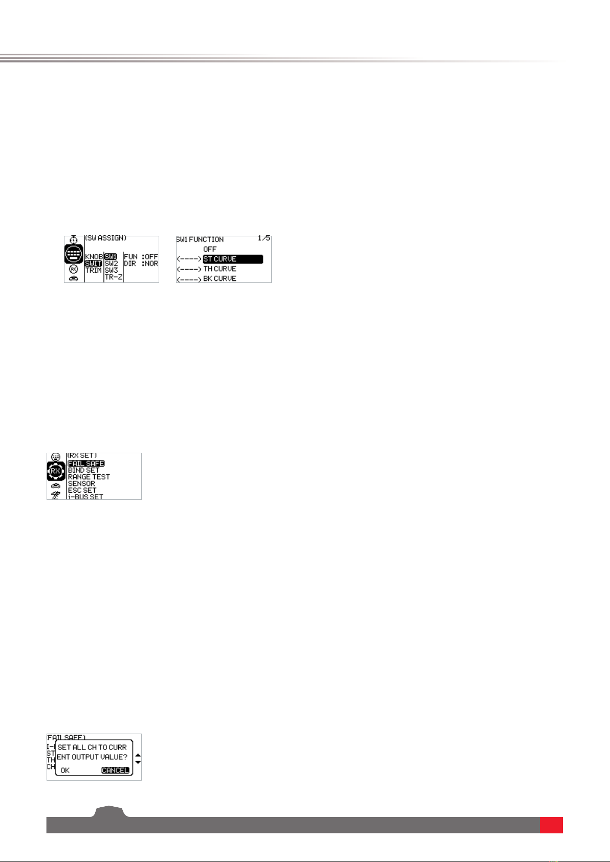
6.15 Key Settings
The key setting function is to assign switches to some functions in order to control the output of
the actions needed through the specified switch. According to the types, it includes trim, switch,
and knob.
Function settings:
1. In the SW ASSIGN(switch assignment) menu, select a item and press the OK key.
2. Select the item you need to adjust by pressing the UP/DOWN key. Press the OK key to enter
the edit state. Then adjust it by pressing the UP/DOWN. Press return after adjustment.
3. Test the function to confirm that all channel outputs operate normally as expected.
6.16 Receiver Settings
The RX SET(receiver setting) menu provides a number of function setting menus to allow you to
set up the receiver system in all aspects. That is, FAILSAFE, BIND SET, RANGE TEST, SENSOR, ESC
SET, and I-BUS SET.
Function settings:
In the main interface, press the OK key to enter the function menu. Select the RX SET(receiver
setting) menu by pressing the UP/DOWN key. Press the OK key to enter the function setting
interface.
Failsafe is an important safety setting. It can be used to protect the model from loss or reduce
the degree of loss when the receiver loses signal without control. In addition, it plays a role in
protecting personnel safety.
You can set the data in case of loss of control for all output channels. There are three output
states. If the state is not set, the output is low level state. It is mainly for giving you a reminder.
The no output state is also an output of a low level, that is, no signal state. If the output is set,
there is the corresponding output according to your requirements. The specific mode settings
depend on the terminal device and operation requirements. For example, some governors take no
signal as the stop signal. If the out-of-control receiver needs to output a low level no signal, the
governor will enter the protection. Another example: If it is an engine, we need to output a brake
signal to the brake servo if it is out of control, we need to set that there is an output and it is in
the brake state.

15
Function settings:
1. In the RX SET(receiver setting) menu, select the FAILSAFE by pressing the UP/DOWN key. Press
the OK key to enter the function setting.
2. Select the item you need to adjust by pressing the UP/DOWN key. Press the OK key to enter
the edit state. Then adjust it by pressing the UP/DOWN. Press return after adjustment.
3. Test the function by powering off the transmitter to confirm that all channel outputs operate
normally as expected.
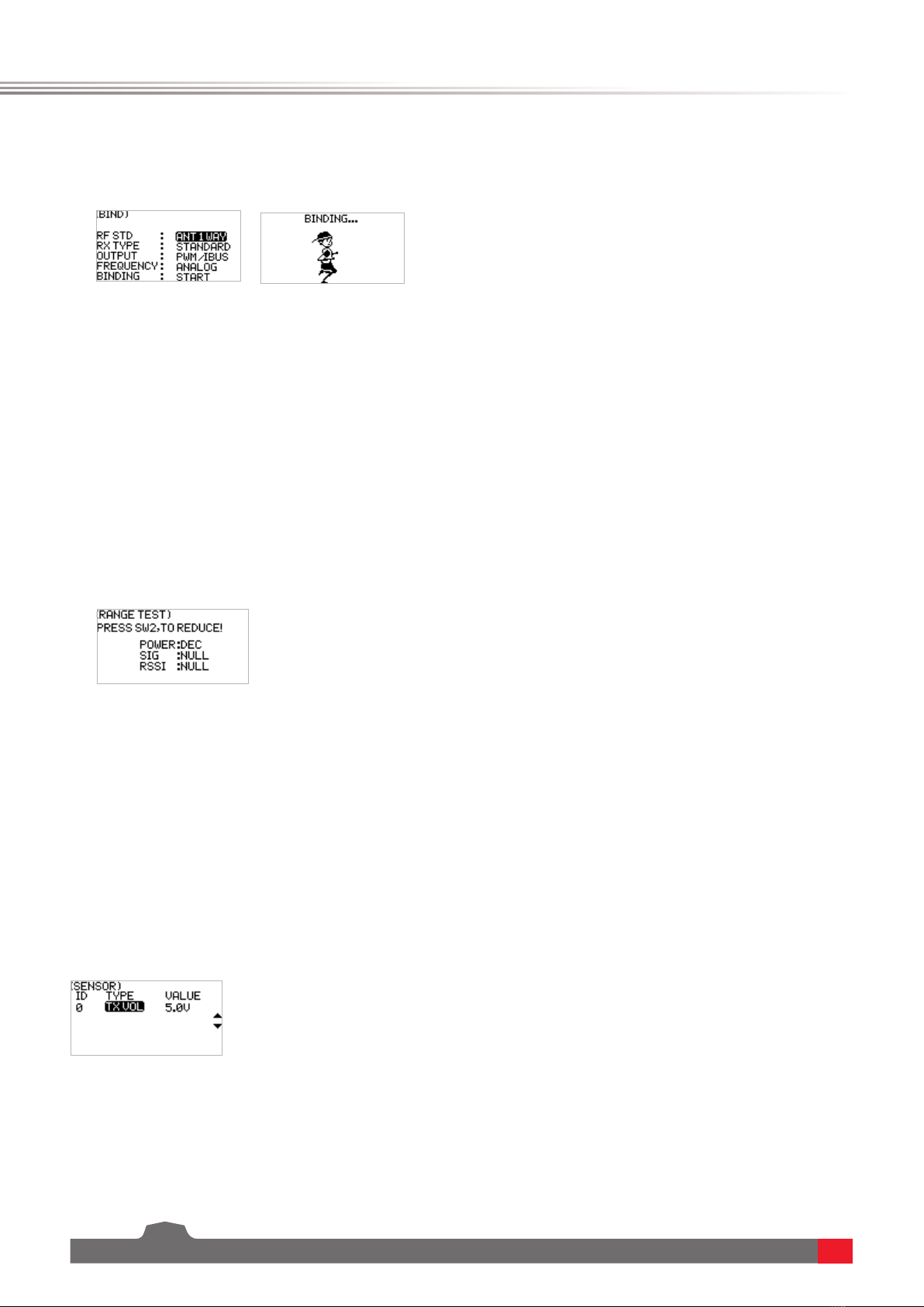
6.18 Receiver Settings - Bind Settings:
The transmitter and the receiver have been bound with each other before delivery and can be
operated directly. If you want to replace the receiver, you need to bind the new receiver with the
transmitter by using the binding function before they can be operated normally.
Four parameters - RF type, receiving type, output mode, response speed - and a BIND key are
provided for setting purpose.
RF type: There are two options available, ANT1WAY one-way and ANT2WAY two-way. If you are
using a two-way receiver, it is recommended to select ANT2WAY two-way, which may bring you a
better experience with more information feedback.
ANT1WAY means a one-way mode. In this mode, only the transmitter gives commands to the
receiver; while the receiver outputs and performs commands received from the transmitter. The
advantage is that it can ensure simultaneous operation by more users on the same site with less
interference.
ANT2WAY means a two-way mode, which enables intercommunication between the transmitter
and the receiver to be configured with the corresponding functions, so that the basic information
of the model can be provided to the user in real time. For example, if you want to know the
battery voltage of the model vehicle, you can enable this option and bind the receiver configured
with this function, then you can read the battery voltage value on the transmitter.
Receiver type: Two options are available, namely standard receiver and two-in-one receiver,
which can be selected according to the receiver you are using. The option of two-in-one receiver
means a receiver configured with a ESC; however, standard receivers are supplied by default. For
details, please visit our website to learn more about relevant models.
Output mode: There are four optional output modes (combination of two output modes),
i.e., PWM/SBUS, PPM/IBUS, PWM/IBUS, PPM/SBUS four output modes, which can be selected
according to actual needs.
Servo frequency: There are three optional output modes, i.e., analog, digital and others, which
can be selected according to the type of servo. The digit following each option is used to set the
frequency of the servo output.
Note: The frequency of analog servos, digital servos and other servos are 60HZ, 380HZ and 50HZ-
400HZ respectively.
Function settings:
1. In the BIND SET menu, select the item to be adjusted by pressing the UP/DOWN key and press
the OK key for editing. Set the desired value by pressing the UP/DOWN key and press the OK
key to confirm the adjustment.
2. After the adjustment and setting are completed, select START by pressing the UP/DOWN key
FS-G7P
Digital Proportional Radio Control System
16
and press the OK key to bind with the receiver. For details, please refer to the chapter for
binding operation and the Quick Start Guide.
3. After finishing the above step, carry out a test to confirm that all channel outputs are
functioning as expected.
6.20 Receiver Settings - Sensor
As an interesting feature for two-way communication systems, sensors can be used to send back
some information you need through the receiver.
Our transmitter can support up to 15 different types of returned data to provide you with the
feedback of seven basic parameters, i.e., TX VOL(TX voltage), RX VOL(RX voltage), BVD VOL(BVD
voltage), SIGNAL(signal intensity), NOISE, SNR(noise rate) and RSSI. BVD: detect an external
power supply. It is recommended to use this function to monitor the battery voltage and give an
alarm in case of a failure.
Function settings:
In the SENSOR menu, scroll pages by pressing the UP/DOWN key to check relevant information.
6.21 Receiver Settings - ESC Settings
The ESC SET(ESC Setting) menu is an additional option provided specially for FLYSKY two-in-
one ESC, which is used to set the two-in-one governor more precisely to ensure its optimal
performance. To enable this setting, you need to switch the receiver type to the two-in-one option
in the Receiver settings - Bind Setting menu.
Three parameters, namely operating mode, battery type, and drag braking force can be setup here.
6.19 Receiver Settings - Range Test:
As an important function, it is recommended to conduct the range test before each operation to
check whether the remote controller is functional or environmental conditions are normal.
Working principle: It is aimed to conduct a narrow-ranged test by actively reducing the power
of the transmitter, in order to realize quick inspection of the transmitter system and the
environment. There are three parameters (power, signal, RSSI) displayed and indicated on the
transmitter interface.
Function settings:
1. In the RANGE TEST menu, directly press the SW2 key to conduct the test.
2. You should keep the transmitter still during the test, but you can move your model at this
time. If there is no problem in the test within a certain range, the device can be used normally.
Other manuals for FS-G7P
2
Table of contents
Other Fly Sky Transmitter manuals


