Flycker Vision-260 User manual

!
Legends
Important
Hints and tips
1Aircraft instruction :
When This product is shipped, the default calibration has been done,
Please do not modify it yourself. Otherwise, we are not responsible for
warranty repair. We reserved the finally explanatory ri gh ts ! l at es t ve rs io n
reference home page。Please visit our offcal website for the new updated
user manual and other information.
www.flycker.com
User Manual
Trailblazer Series
Vision-260
Charge the remote control and Battery first,
when opening the package.
2
1
11
2
5
3
4
6
8
10
11
1. Motor M1-M4 power system. Part 6 will be a description of “how to mount
propellers”
Camera
5.8 Video Downlink antenna
Aircraft adjusting parameter micro interface
2.
3.
4 . Video Downlink FM (Frequency Modulation) button is des cribed in detai l with reference
to Part 9.
5.
1
M2 M1
M4
M3
Battery level led lights Displays the battery level
of the remote controller and aircraft battery charge
instructions.
6. 。
7.The color LED lights flashing at tail of aircraft. The information status has cross reference to flashing
Front LED indicator, The Front LED lights show the orientation of the aircraft and random shipments
TF card slot
(XT60)Power input plug
status. Refer to Part 5.
8.
9.compass
10.Landing gear
11.
Chargin g indicator
Please use power adapter
Power
Displaying the battery level of the remote
controller
Low battery
100%
75%
50%
25%
Full of charged
In cold weath er, If there's no reaction when you press th e ON button,
wait 10 secon ds and press it a gain. please do n't pound on the button
of the remote control
7
HEAD
REAR
9
Remote control instruction
USB Input
voltage3.7~5.5V
Charger
410 5
13
2
12
11
6 7
8
9
3 Battery
3
7
3
AIRCRAF T IN STRUCTION
figure2-1
Remote control
instruction
5
if you need
Also another USB power outpu t can be use for charging , for example:
mobile phone battery charger a nd computer.
Aircraf t inst ruction :
figure 1- 1)
)
Remote control ler and aircr af t battery charge in structions.figure 3- 2)
)
This product includes electronic components. Please read this manual carefully before operation of
Dropping it may damage the aircraft. Please, don't modify it by yourself. You can not execute this product.
any upgrade or maintenance on the product. Contact your dealer or Flycker customer service.
1.Long press”turn on/off”button
2.Batter y level led lights Displays the batter y level
of the remote controller. Reference part 3
Cameras/Video record button: Long
press button again to stop recording . Aircraft
took pictures,
Press (three seconds)
shor t press for video recording. And short
pictures when video recording.
can not take
4.Left control stick. Control to take-off and to land. Rotating to the left
or to the right is described in detail in reference to Part 7
Handle
8.
11.Charge status indicator
12.Remote control Charging interface
GPS: When aircraft on GPS mode , it’s smooth flight .ATTI: suitable for
7.
novice .S-ATTI: sensitive respond, but this is not for a novice aircraft user!
9.ON/OFF status indicator
10.Hanger for lanyard
6.Return home-button. Switch to 'Off' and turn to manual operation. Switch
to "H" and enter Return Home mode. Reference Part 8.
5.Right-control stick. Control to fly for ward, backward, left and right, is
described in detail in reference to Part 7.
battery.
Please read this warning a nd rigid adherence to this i nstruction an d
printed word on the ba tter y su rface carefully before use the
On occasions of failure generated i n violation of thesetting method,
application method and notices as stipulated in the operation
instructions, users take on this resp onsibility.
3.
Important
Legends
This version instruction applied for version number 1.2 vision-260 aircraft.
About version number cheacking method,pls consult offical Flycker service center.
V 1.2
7
4
4-1 Waring and Attention
Check the aircraft batter y and the remote control batter y, please charge or replace the other
fully charged batter y if became low battery before use.
Check that there is no damage on the aircraft and propeller. If such damage exists, the damaged
propeller must be replaced with a new one.
Fly away from damp environment such as windy and rainy days, fog or snow.
Select open spaces, and that there are no buildings to fly around. a group of buildings together
will affect the normal flying operation.
t fly in the Antarctic and Arctic
1.
2.
3.
4
5 Can'
6.Don't fly within 'no-fly areas' restricted by law.
Turn on motor
The motor will wait control order 10 se conds, if no order
within 10 sec onds , it will stop work
Please don't shake control stick when flying, and don't
turn off the remote control directly; the aircraft will fall
down and it will most probably be damaged.
Stop the motor
Front
Back
Left Right
Go up
Go down
Rotate
to the
left
Rotate
to the
right
The s eco nd
lev el
Lev el on e
Indoor
The combination of light flash
GPS
ATTI
outdoor
S-ATTI
H
Can use
Low voltag e Fast Yellow Thre e Fla shing Ple ase E xecu tes
com man ds th at ret urn
Fas t Yello w Two Fla shi ng Pl ease Exec ute s
com man ds th at ret urn p lease exe cut e
An
the
open
area
GPS
ATTI
S-ATTI
H
Installation and removal of the propellers.
The corresponding propellers are set
intothe corresponding motors
Flycker-free: ver y good signal.
Flash once: moderate strength signals
Flashes Twice: signal strength is
not sufficient
/
M-1
M-4 M-3
M-2
M1-M3 The same propeller M2-M4 The same propeller
The LED lights
at tail of aircraft
Rot ate t o the lef t,
Rot ate t o the lef t
Go up
Go down
Front
Left Right
Back
Aircraft unlock point
9
UNLOACK
PROPELLER
Fix propeller
Right Control sticks diagram of operation
8
Left Control sticks diagram of operation One-key return and out-of-control
protection
One-key return and out-of-control protection function is based
on good signal environment
“H”
Head of aircraf t flying
56
PLL-FM ways and frequency range
Vision 260 recommends automatic searches for channels
with the display device PLL-FM ways.
The distance between the
operator and the aircraft
must be greater than 5
meters before flying
CH
FRCH CH 1 CH 3
CH 2CH 4CH 5CH 6C H 7 CH 8
FR 1/ BandA
FR 1/ BandB
FR 1/ BandC
FR 1/ BandD
FR 1/ BandE
5740 57 60 5780 5800 5840 5 860 5880
5705 5685 56 65 5645 5885
5905 5925 5945
5865 5845 5825 58 05 5785 5765 5 745 5725
5658 56 95 5732 5769 5 806 5843 5880 591 7
5733 5752 57 71 5790 5809 5 828 5847 586 6
5820
Read and follow all installation, operation, and maintenance in formation carefully
before using the product. If user do not obey a prescribed procedure to operate, in
this cases exclude our liability
!
The remote control operating instructions
Description of LED light at the tail of aircraft.
Figure 6-1
The LED lights at tail of aircraft
The combination of LED light flash (Table 5-1)
Left Control st icks
diagram of operation
Figure 6- 1 Install the Propellers and Remove the propeller
Form 9-1 Freq uency range ill ustrated
The remote control
operating instructions
Warning and Attention
!
4-2 Ready
1. 'sPlease find an open space, to avoid damage to the personal and property of other
3. to do the calibration compass .reference part 4-3Af ter everything checked out ,
2
.
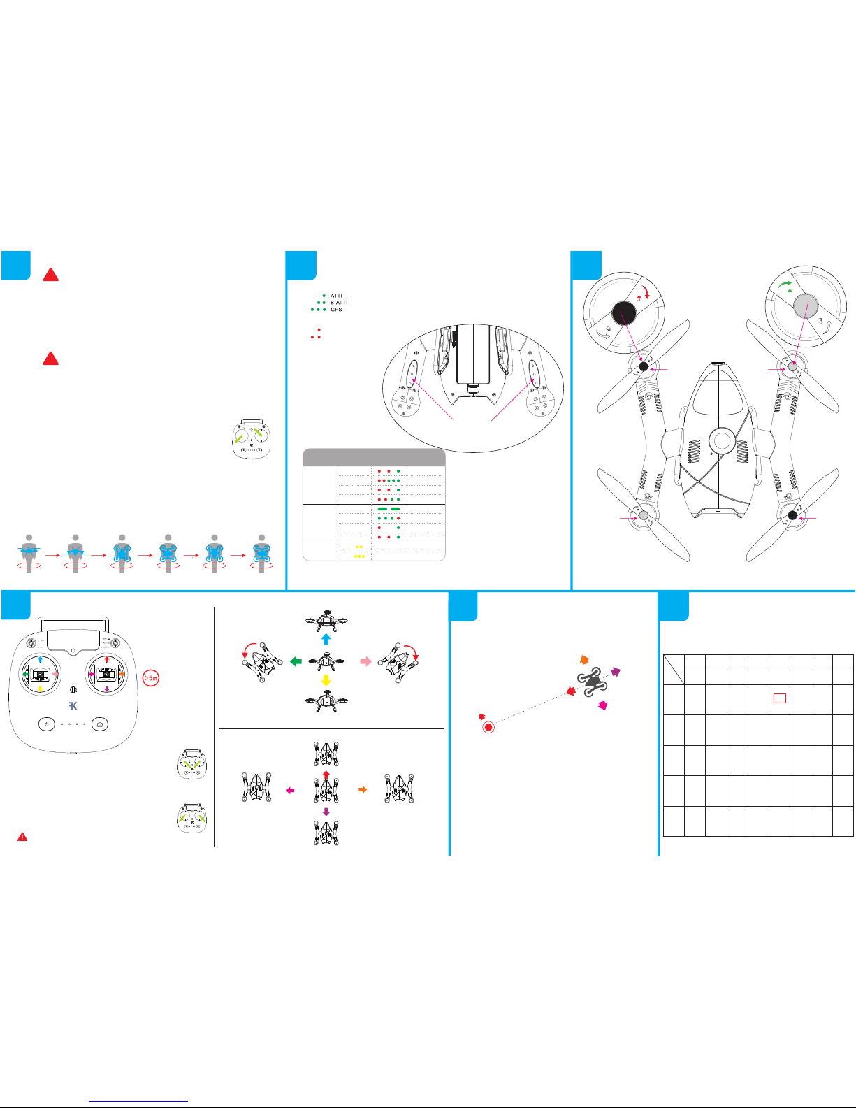
4-3 Calibrate the compass
Light flash instructions for each mode
Red LED flash to indicate signal status in GPS mode
Can use
Can use
Can use
Can use
Can use
figure 7- 2)
)
figure7-3)
)
figure 7- 4)
)
Right Control sticks
diagram of operation
figure 7- 4)
)
outdoor
US handling
figure 4- 1)
)
figure 7- 2)
)
In the occasion of failure, generated in violation of the setting method, application method
and notices –as stipulated in the operation instructions-- it is not Flycker's responsibility
S
tep 1:
When the aircraft returns safely. The re mote control will be
Ste p 1: Pull left remote control joystick to shut down the motor slowly
to make t he motor stop rotating .
Step 2:
locked when push /pull and hold control stick to splayed
(as shown in the figure7-3 ) af ter the motor is stopped, yo u \
can turn off the remote control
PLL-FM ways: To adjust different frequency bands, use the
"L"-shape screwdriver. Press the FM button on the aircraft.
Factory default frequency range is sent 5820
Hold the motor and check the rotation.
of propellers to see if it conforms to
the markings of how to install and
remove.
Check the aircraft batter y and the remote control batter y, If user operation causes
batter y discharge, exclude our liability.
4.) The airc raft i s picked up , a nd then it is turne d clockwise twi ce. Please comp lete in two min utes. Reference to
Figure 4-2
If the light is off, during t urned clockwi se two times, please re-do Calibration
That's the whole calibration process. So, ligh t is glowing brig htly at tail of aircraft and put on flat surfaces wait
for Harvester Colle ction.
The Calibration Successful When lights flashing at tail of aircraft. Switch “One -Key Return” to “O FF” and
observes the color of the light flas hing at tail of aircraft
The color of the light flashing Match with form 5-1 , that i s ready to fl y
figure 4- 1) ompass ca libration procedure
C
)
Please stop flying when the yellow flashing light on the tail is on. The flashing green light on
the remote warns of caution.
Figure 8-1 On e-Key Return diagarm
3.
2.
1.Please calibrate the compass for first ti me use, or a flight of more th an 2 km
Do not Calibrate the compass in a stron g magnetic interf erence plac e
Don't bring near i ron objects such as keys o r mobile phone en vironment
in most recent fly.
4.Please pa y attention to protect t he disk module, d isk module; sta y away from
magnetic fields, otherwise it will eas ily lead to data disorder, unable to unlock
Calibration Procedure.
1.) Press lo nger on the rem ote on-button and status indicator will l ight up.
2.) Put batter y in fir st a nd immediately put flat surface wh en the aircraft 's tail
LED flash light comes on. Place aircraft horizontally to avoid moving or shaking,
and so forth, facing th e tail of the a ircraft.
3.)
This remote control referen ces US handling a nd how it operates. At the top lef t, there is a switch to
'H' gearing. At the top right of the remote control, there is a switch to "S-ATTI" gearing. To per form
operation on control sti ck (left or right), reference to Figure 4-1Please confirm red light i s glowing brigh tly at
tail of aircraft , proce ed to Next step when red lig ht is glowing bri ghtly, otherwise, Do It Agai n
The system will record the location of where the user unlock the aircraft,
and will consider it as 'Home' location.During flight, Switch the
knob (on the top left corner) to "H".Aircraft will comply return function.
The aircraft will automatically lift to 30 meters height and fly forward the
user.Aircraft will hover about 2s after aircraft reach the end of returning,
and then slow down. Right now flight states could be controlled by
control stick(but throttle does not work).It is convenient for aircraf t
to look for more suitable landing. Motor will slowly stop until aircraft
landing completely.Aircraft will comply return function when it can not
receive instructions from the remote control.
 operating instructions")


