flyingwings Hornet Mini FPV Racer User manual

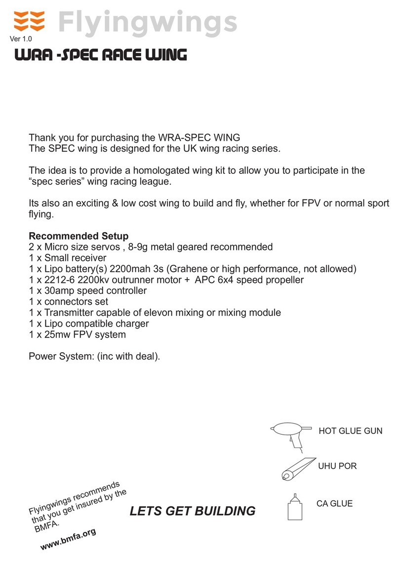
Thank you for purchasing the Hornet Mini FPV Racer
Race your mates around a pylon circuit, or through the 250 quad gates, if you dare !
The Hornet is designed to be kept light, using a micro FPV TX and camera, the
lighter, the faster.
As well as this power system you will require:
2 x micro servos 5-8g
1 x micro Receiver
1 x Lipo battery (800mah 3S 11.1v)
1 x Mini FPV system such as the Elgae FOV160-200
1 x Transmitter capable of elevon mixing or mixing module
1 x Lipo compatible charger
1 x FPV Receiver, & goggles
Power System: (inc with deal).
1 x 1806 2280kv brushless motor
1 x 12amp speed controller
1 x GemFan 5x3 or similar prop
LETS GET BUILDING
Hornet Mini FPV Racer
Flyingwings recommends
that you get insured by the
BMFA.
www.bmfa.org
CRITICAL DATA
CENTRE OF GRAVITY 130mm BACK
FROM THE NOSE POINT
TARGET FLYING WEIGHT
240-260 GRAMS
UHU POR
HOT GLUE GUN
CA GLUE

STEP
STEP
1
2
1. Turn the wing over and insert the
carbon strip spar.
Cut the battery & radio
compartment out to lines drawn on
the wing. Then join the wing.
Use the full size template on
the template sheet

STEP
STEP
3
4
STEP 4
Glue the ply side panels to the
fuselage,
Glue motor mount as shown and then
the ply plate.
Glue the fuselage to the underneath of the wing centrally, note that this leaves a
gap, allowing the installation of a standard board camera
gap

Installation of servo adaptors:
Open up the top hole on each ply horn so that the threaded part of
the metal servo adaptors are snug but can turn in the horn. Put the
washer and nut on (not easy when you have fingers like sausages
!). Tighten the nut so the adaptor is firm but can still turn. A blob of
CA glue on the end of the nut will stop it from coming loose.
blob of CA
Glue
washer
nut
STEP 4
Hinging elevon,
Method , UHU Por hinge. Run a small bead of glue along the rear top edge of
thetrailing edge of the wing and the same on the leading edge (LE) of the elevon.
Allow glue to set for 5 minutes. On a flat surface bring the two edges together, the
glue fuses together giving a strong flexible hinge, magic.
STEP 3a

Attaching the elevon horn.
The push rod should run parallel to the centre line of the wing.
Using a ruller draw a line on the elevon where the horn should be
situated. Press one of the horns into the foam to leave an
impression, cut this with a knife so that the horn sits in the elevon
around half depth, glue in with plenty of CA glue.
Horn location
STEP 6
Radio Installation:
Set up your servos as shown in the Radio Setup section and
double check everything is working in the correct manner outside
of the model before installing it into the model.
Two pre-cut holes have been made into the wing, these give you
a guide to fit your servos. All micro servos vary in size a little,
so you may have to cut around the servo to sit them into a
snug fitting hole, take your time with this.
1. Place your servo over the hole, draw around it to show
where more foam needs to be removed.
2. cut carefully around, the line draw and prize out the
foam, keep checking for fit with servo.
3. Cut a line around 2mm deep (no deeper) from the servo
cable wire output to the receiver location, push the cable into the
slot.
STEP 5
USE SERVO TEMPLATE
SHEET

Installing the horns & pushrods.
SWITCH ON YOUR RADIO AND CANCEL ALL SUB TRIM
SET TRIMS TO NEUTRAL
Screw the screws into the horns so that the points of the
screws are just proud, Line up the horns as shown in FIG
5C, press down the horns, then screw them right down, get
the bottom part of the horn, align screws and screw down
until the horns grip the elevon, but not too tight.
Screw the clevises onto the pushrods halfway, attach the
clevis to the servo horn, Set the elevon position slightly
upwards as shown, mark the pushrod with a felt tip and
make your z-bend at this point. Note the horn holes may
need to be enlarged slightly,
Use a ruler to set neutral position
STEP 8
Attach wing tips with glue
Push rod assembly:
Glue the plastic clevises onto the end of each carbon push rod,
with CA glue. Attach the piano wire a 20mm overlap to the carbon
rod. Use a generous blob of CA glue to coat this area. Slide the
heatshrink tube over and shrink using a heat source.
30mm 40mm
CA Glue
Heatshrink Wire
STEP 7

RECEIVER
centre of gravity
130mm back
from nose
Cut small slots
2mm deep with a
sharp knife, push
servo leads in
ESC
Hold battery in with a small
piece of velcro, run cables
below it
Carefully cut an aperture for
your camera to snugly sit in.
Cut a small hole behind and
feed the cable through
VTX transmitter, cut a small tray
for this to sit in.
Note, on a small wing, keep this
part close to the centre line to
maintain balance

POWER SYSTEM SETUP
Motor assembly and wiring
Speed
Controller
Battery
JST
connectors
Receiver, throttle
channel
Always do the motor setup with no propeller attached for safety.
In some cases the motor will not react to sudden throttle opening or stutters, this is resolved
when the propeller is attached.
Trouble shooting:
The motor will not start
> Always switch on the transmitter, set throttle to zero, then switch on model and wait for start up
sequence (beeps)
> Incorrect wiring, check battery to speed controller and controller to motor polarities
> Check servos are working, if not , there is a problem with the battery to speed controller
connection or a crystal problem. check with a separate battery.
Motor runs the wrong way
> As with all brushless motors there is 3 wires, left, middle & right. The middle connects to the
middle of the speed controller, the two out wires, left & right can connect either way and will dictate
the direction the motor spins.
Insulate
connection
each

Left Aileron: right servo travels back, left travels forward & vice versa
Up Elevator: right servo travels back, left travels back & vice versa
Viewing the model from the
rear, the motor should run
clockwise with propeller put
on backwards.
Recommended control throws measured at trailing edge of elevon.
Up/Down +/- 7mm, Left/Right +/- 7mm
Important : When setting control throws, note that all 4 settings
(up,down,left,right) are the same whatever value. Ie all 75% or all 65%
Radio setup
There is small writing on the
propeller near the hub, this
should face towards the
front of the model
Indented prop size
marking near root of
prop eg 5030 should
face forwards
Setup and flying. Set the elevon neutral position so that it follows the
sweep up from the bottom of the wing as if it were part of the wing, then
add 3mm of up elevator, this is the neutral position.
The Hornet can be flown in medium breezes, but choose a calm day for
your first flight. Hold the leading edge of the wing and give a gentle toss
with full power to launch then reduce throttle.
Help Line 01908 615163

Table of contents
Other flyingwings Toy manuals
Popular Toy manuals by other brands
Bontempi
Bontempi Toy Band Star 12 3109 owner's manual
Techno Gears
Techno Gears Bionic Bug instruction manual

Fisher-Price
Fisher-Price Loving Family Musical Surprise Party quick start guide
PLANEPRINT
PLANEPRINT Funbus manual

Eduard
Eduard Mirage F.1B interior S.A. quick start guide
Tabata
Tabata ReefTourer Underwater Viewing Bucket manual
