FLYTEAM FREE BEE User manual
FREE BEE
www.flyteam.sk

2www.flyteam.sk
FREE BEE
Dear customer, congratulations on the purchase of the Free Bee model. To enjoy building and
flying the model most,please read carefully the building instructions before you begin and
make sure that you understand the building process.
DESCRIPTION OF THE MODEL:
The model is completely made of the expanded polypropylene (EPP), and its design is
optimised for easy flying. Its light weight (about 300 grams) makes it an ideal model for flying
in any place – e.g. school playing field or in the street. It has been designed for not only the
experienced pilots, but with the advanced modellers in mind as well. Thanks to its well thought
out design the actual building process would take about 270 minutes.
MODEL ASSEMBLY:
All joints should be glued using thin CA glue. In the first phase of work, tack-glue the
joints so that they just hold together; then only after checking their position and symmetry
glue permanently. Take care not to let the glue penetrate the EPP and stick your fingers to the
plastic structure. Building the model is not difficult provided you have an elementary experience
with EPP model building. Remember that the EPP has a somewhat “rubbery“ properties, so do
not apply force handling and processing it, as stretching or compressing the model parts may
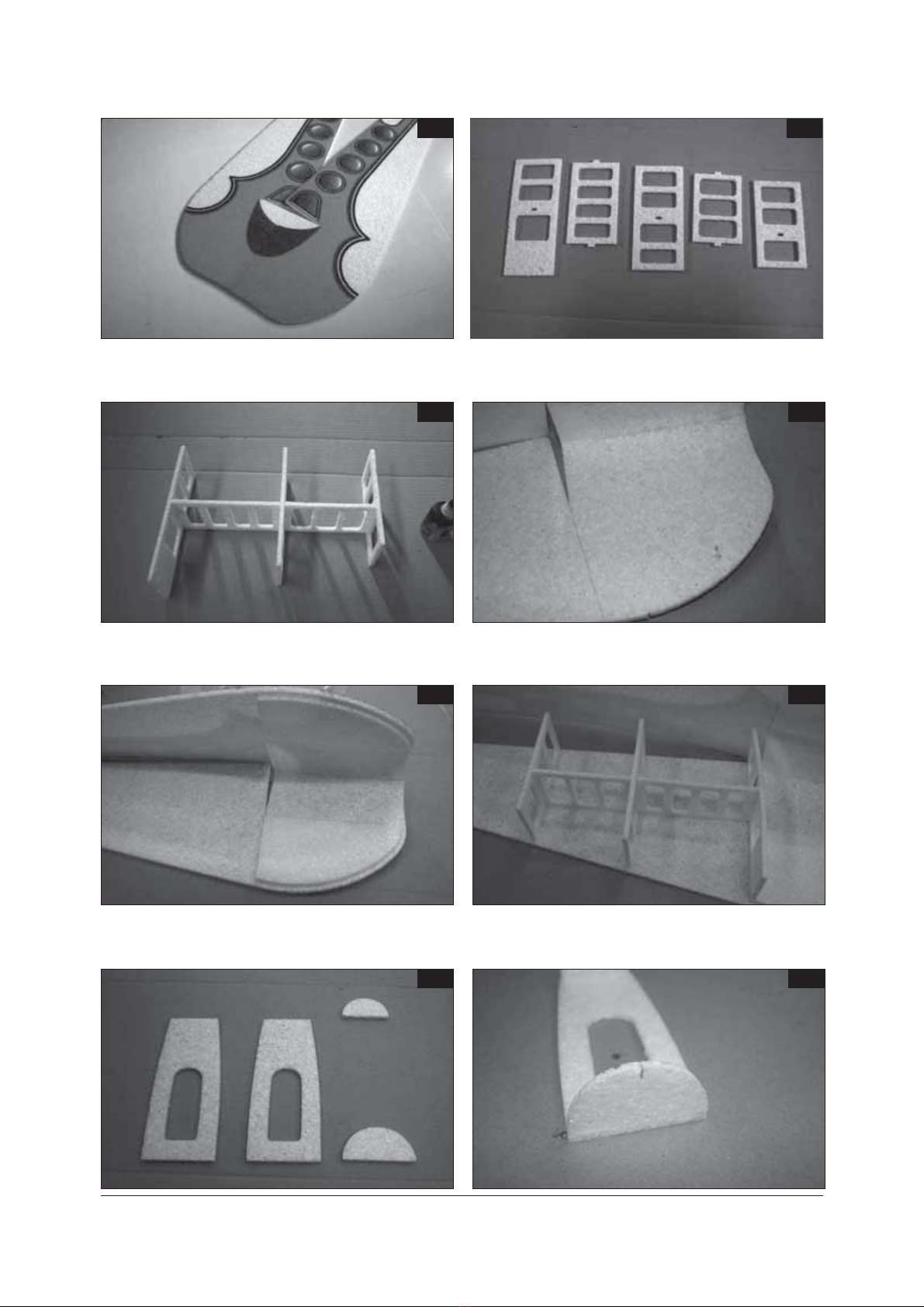
cause their eventual distortion. First glue together the fuselage side panels (Fig.1). After glue
has set, bend the side panels at front and leave weighted for some 20 minutes; that would
facilitate handling them and later on and also gluing of the complete fuselage. Then make
the fuselage bulkheads ready (Fig. 2), assembling them as per Fig.3. From the inside of the
side panel, using a marker pen, draw an auxiliary line from the cockpit (Fig.4). Glue the front
fuselage reinforcement to this auxiliary line so that the distance of the reinforcing part from
the bottom of the side panels is 5 mm (Fig. 5). Now glue the fuselage bulkheads to one of the
side panels (Fig. 6). Use a flat even working board to keep the fuselage straight during the
process. Ready the battery and servo holder (the keel and 2 half-circular bulkheads) (Fig. 7).
Mark the axis on the half-circular bulkheads to facilitate assembly with the fuselage sides (Fig.
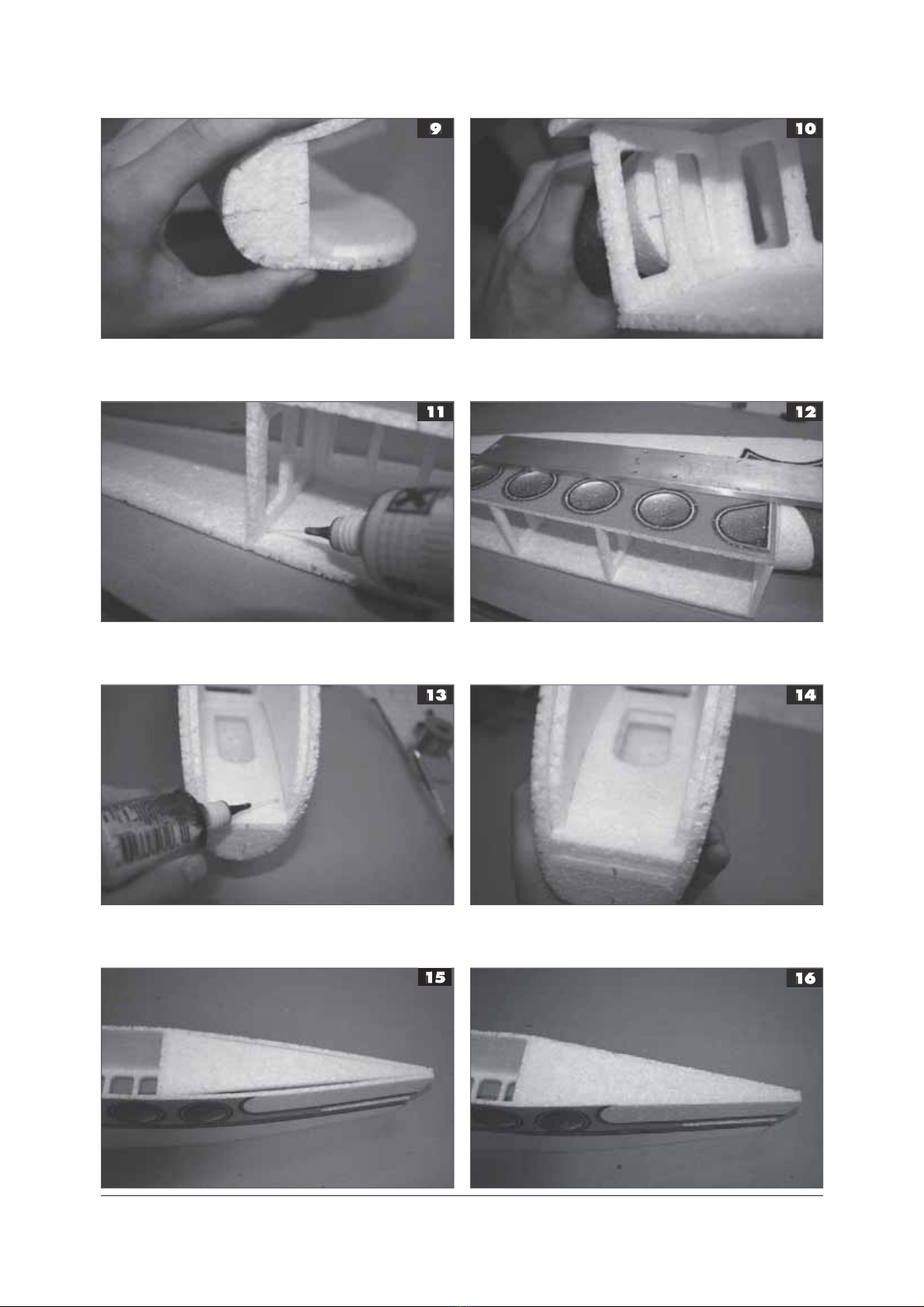
8) and glue them also to the keel member. Then glue the complete holder into the nose and
the cockpit section of the fuselage to the side panels; ensure to have the axes of the fuselage
and bulkhead aligned (Fig. 9, 10). Glue only the bulkheads, NOT the keel now. Then glue also
the other side panel to the bulkheads. Prove first, however, that everything is aligned well,
then, using a weight, secure the position of the side panel and thoroughly fill the joints with
glue. (Fig. 11, 12). The thin CA glue would flow through the joints not requiring to disassemble
the structure for gluing. After a check that the fuselage is straight and true flow the glue
into the joint of the keel in the front fuselage and glue in place the second part of the keel
so that it would seat on the reinforced front part of the fuselage (Fig. 13, 14). Using several
drops of the CA glue, tack the upper part of fuselage in place (Fig. 15), after testing it for
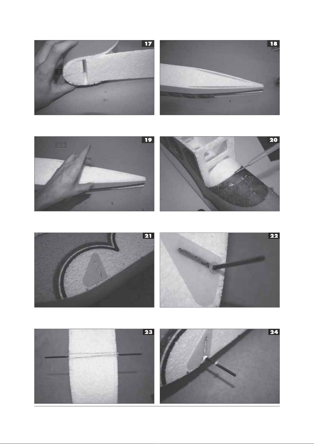
alignment, glue it along the full length of side panels (Fig. 16). Now glue the fuselage lower
part in the same way (Fig. 17, 18, 19). Check again the alignment of the complete fuselage.
Using a sharp modelling knife, cut away the fuselage front at the cockpit canopy (Fig. 20),
this opening shall be used later on to lead the servo cables to the receiver. Using the Fig. 21 as
a guide, glue the undercarriage reinforcements in place. The groove for the wheel axle should
be placed some 2 mm in front of the fuselage bulkhead. Insert the axle through the fuselage
and secure with a glassfibre washer, which should be carefully glued in place by CA glue
(Fig. 22). Put in place the rubber loop, making the undercarriage spring (Fig. 23). Place the
glassfibre end-stop washers in a distance of some 15 mm from the ends of axle, and carefully
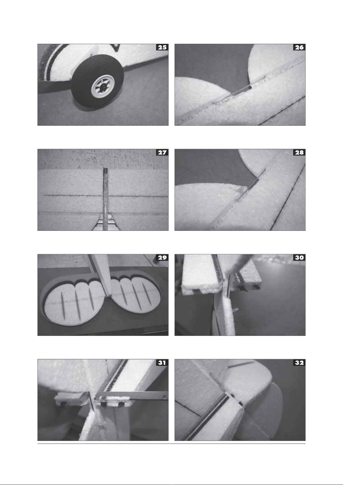
glue with CA (Fig. 24). Once the glue cured, slide the undercarriage wheels on the axle and
secure with the QuickLock washer (Fig. 25).Glue the aluminium wire joiner to the elevator
(Fig. 26). At a distance of 75 mm cut, using a sharp modelling knife, a slit some 4 mm deep
and glue into it the carbon composite strip of 3 x 0,5 x 330 mm dimensions (Fig. 27). Then
glue the elevator control arm (Fig. 28). Now glue the elevator into the fuselage (Fig.29) and
glue in place the rudder hinges (Fig. 30). Using a sharp modelling knife, bevel the fuselage
edges so that the rudder may deflect freely (Fig. 31) and glue the rudder (Fig. 32) and its arm
(Fig. 33) in place. Glue into the fuselage also the tailskid and its reinforcement (Fig. 34, 35).
Using a sharp knife, cut an approximately 1,5 mm deep slit into the wing and press into it the
carbon fibre spar; glue using the CA (Fig. 36). Note, the spars MUST be one above the other.
The remaining length of the spar from the forward part of the wing could be used to reinforce
the rear of the wing centre section (Fig. 37). Glue the upturned tips to the centre section (Fig.
38) and the reinforcement for the rubber loop, fixing the wing to the fuselage (Fig. 39,40).
Glue this reinforcement on the wing centreline.Using the sandpaper, sand away any bumps
on the fuselage front and glue the motor bulkhead in place (Fig. 41), then the motor bearers
to the bulkhead (Fig. 42).The fuselage is designed with the motor downthrust in mind, but
ensure that in case of need the motor bearer could be unbolted and have washers inserted to
change the downthrust angle. Insert the motor speed controller between the keels and a place
it close to the motor bulkhead. Connect the controller to the receiver (Fig. 43). Between the
keels, some 100 mm from the nose of the fuselage, cut an opening for the servos. Push the
servos into the prepared openings (Fig. 44). You may secure the servos in place using a drop
of CA glue at the brackets. Connect the servos to the receiver and check the neutral position
and the correct spacing of channels.Using a sharp knife, cut the canopy part as per Figs.45 and
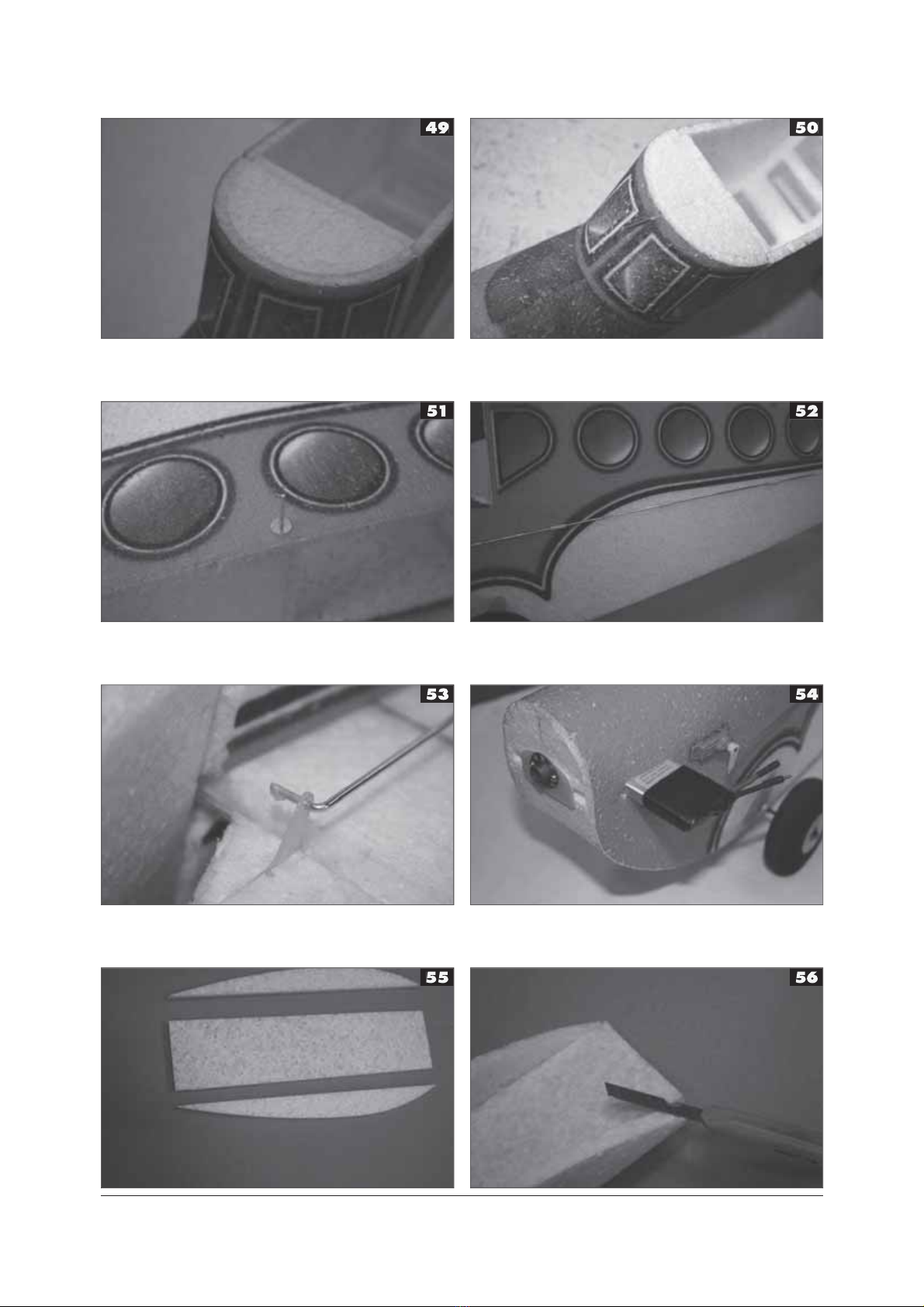
46. If the canopy fits well, glue it in place (Fig. 47, 48). Last, glue the reinforcing bulkhead
into the canopy (Fig. 49). Glue the front wing holding dowel of 2 x 100 mm aluminium wire
and secure it with the glassfibre stop/washers (Fig. 50). Similarly, glue the rear wing-holding
dowel of 1,6 x 100 mm aluminium wire and thE glassfibre securing washers from both sides
(Fig.51).Slide the 3 x 10 mm tubes (three each side) and insert their end with the Z bend
into the servo arm (Fig. 52). On the empennage side bend the wire to make an L and using
a drop of CA, secure them from accidental sliding out (Fig. 53). Then glue the push/pull rod
guide pillars into the fuselage.In the fuselage front, forward of the servos, cut between the
keels an opening for propulsive batteries (Fig. 54). Glue the 5mm part of EPP, shortened to
the 70 x 300 mm dimensions, between the two wing ribs (Fig. 55). Then cut away the excess
material which could hinder gluing the wing into the fuselage (Fig. 56); glue the part to the
wing centreline (Fig. 57). Connect the motor (Fig. 58) and the model is finished. The Free Bee
model is not too sensitive to the position of the centre of gravity, it should lie, however, some
90 mm from the wing leading edge. Thanks to the excellent flight characteristics there is no
need to limit the control surface deflections. The model is very docile and nice-flying, yet it is
still very nimble and able to be flown in a confined space. The weight in flight with the 600
mAh battery and an HCS C 60W/2-3 motor is 305 grams, giving a wing loading of 10g/dm2.
The Free Bee is not designed to be flown in extremely strong winds, yet it handles well the
wind velocities of about 6 m/s; only keep in mind the necessity to have a sufficient spatial
reserve so that the model would not be blown away from sight.Many happy moments with the
Free Bee model wishes FLYTEAM.
LIST OF PARTS
Name Pcs Name Pcs
Half of fuselage from EPP 2 Wing spar (1x1000mm) 1
Control rod 2 Wheels diameter 74mm 2
Wing of EPP 1 Control surface lever 2
Horizontal tail of EPP 1 Tailskid 1
Vertical tail of EPP 1 Elevator joiner 1
CNC-milled fiberglass sheet 2 Dowels for tie rubber loops 2
Upper part of fuselage of EPP 1 Undercarriage axle, 3 x 120 mm 2
Lower part of fuselage of EPP 1 Quick Lock 2
Bulkhead set, 12 pieces 1 Undercarriage rubber loop spring 1
Rudder hinges 2 Building manual 1
Front canopy 1
You will need the following tools and materials
CA glue, CA glue accelerator, a sharp (modelling) knife. To complete the model you need
the following: a receiver (MZK), two servos (Waypoint W-060), an AC controller (Robotbirds
Pro 10), a battery pack (2 LiPol cells of 600 – 800 mAh), a 60W brushless motor (HCS C
60W/2-3) + 9/5 HD GWS propeller.
FRE BEE
FRE BEE
3
1
3
5
7
2
4
6
8
www.flyteam.sk
FRE BEE
4www.flyteam.sk
FRE BEE
5www.flyteam.sk
FRE BEE
6www.flyteam.sk
FRE BEE

7www.flyteam.sk
FRE BEE

8www.flyteam.sk
FRE BEE
9www.flyteam.sk
FRE BEE

10
POZNÁMKY
www.flyteam.sk
www.flyteam.sk
FRE BEE
FRE BEE 11
FREE BEE
SESTAVENÍ MODELU:
Veškeré spoje lepíme pomocí řídkého vteřinového lepidla. V první fázi spoje jen pojistíme
tak, aby drželi u sebe a následně po kontrole pozice a souměrnosti je zalepíme. Dáváme při
tom pozor na to, aby lepidlo neproteklo skrz EPP a nepřilepili jsme si prsty ke konstrukci.
Stavba modelu není obtížná pokud máte základní zkušenosti se stavbou modelů z EPP. Při
lepení dbejte na „ gumové“ vlastnosti EPP a snažte se při lepení nepoužívat sílu, ta může
způsobit natažení dílů a jejich následné zkřivení. Nejprve slepíme bočnice trupu (obr.1). Po
zaschnutí lepidla bočnice v přední části přehneme a necháme zatížené cca 20 minut, to nám
usnadní manipulaci s bočnicemi i vlastní lepení trupu. Následně si připravíme přepážky trupu
(obr. 2), které slepíme podle obrázku 3. Z vnitřní strany bočnice protáhneme fixou pomocnou
linku vedoucí od kabiny (obr.4). K této pomocné lince přilepíme zesílení přední části trupu tak,
aby distance zesílení od spodní části bočnic byla 5mm (obr. 5). Nyní můžeme k jedné z bočnic
přilepit přepážky trupu (obr. 6). Vše lepíme na rovné podložce, aby trup byl rovný. Připravíme
si držák (páteř a 2 půlkulaté přepážky) baterií a serv (obr. 7). Na půlkulaté přepážky si
naznačíme osu pro snadnější přilepení k bočnicím trupu (obr. 8) a přilepíme je svrchu k páteři.
Poté tento držák přilepíme v přední a kabinové části trupu k bočnicím, dbáme při tom, aby
osa trupu a přepážky byla v jednom místě (obr. 9,10). Přilepíme jen půlkulaté přepážky, páteř
zatím NE. Nyní přilepíme i druhou bočnici k přepážkám. Nejprve si zkuste zda je vše kolmé,
poté si pomocí vhodného závaží zajistěte pozici bočnice a prolijte spoje (obr. 11,12). Řídké
CA lepidlo proteče do spoje bez nutnosti díly od sebe oddělit. Po kontrole souososti trupu
prolijeme i spoj páteře v přední části trupu a přilepíme druhou část páteře tak, aby seděla na
zesílení přední části trupu (obr. 13,14). Pomocí několika kapek CA přilepíme vrchní díl trupu
(obr. 15), po kontrole souososti jej přilepíme po celé délce bočnic (obr. 16). Nyní stejným
postupem přilepíme dno trupu (obr. 17,18,19). Opět kontrolujeme souosost celého trupu.
Pomocí ostrého nože odřízneme přední část trupu u kabiny (obr. 20), pomocí tohoto otvoru
později provlékneme přívodní vodiče serv k přijímači. Podle obrázku 21 přilepíme zesílení
podvozku. Drážka pro osu kol by měla být cca 2mm před přepážkou v trupu. Provlékneme
osu podvozku trupem a zajistíme jí laminátovým kolečkem, které opatrně přikápneme CA
lepidlem (obr. 22). Pomocí gumičky vytvoříme odpružený podvozek (obr. 23). Ve vzdálenosti
15mm přilepíme zajišťovací laminátové kolečko podvozku (obr. 24). Nasadíme podvozková
kola a zajistíme je podložkou QuicLock (obr. 25). Do výškového kormidla vlepíme spojku z Al
drátu (obr. 26). Ve vzdálenosti 75 mm prořízneme nožem drážku hlubokou cca 4 mm a do ní
vlepíme uhlíkovou pásnici 3x0,5x330mm (obr. 27). Poté přilepíme páku výškového kormidla
(obr. 28). Nyní vlepíme výškové kormidlo do trupu (obr.29) a zalepíme panty pro směrové
kormidlo (obr. 30). Pomocí ostrého nože seřízneme trup tak aby se směrové kormidlo mohlo
volně otáčet (obr. 31) a přilepíme směrové kormidlo (obr. 32) i jeho páku (obr. 33). Do trupu
vlepíme ostruhu podvozku a její zesílení (obr. 34,35). Do křídla vyřízneme ostrým nožem
drážku hlubokou cca 1,5mm, do které vmáčkneme uhlíkový nosník, který přilepíme pomocí
CA (obr. 36), poloha nosníků MUSÍ být nad sebou. Zbytek délky nosníku z přední části křídla
využijeme na zesílení zadní části středu křídla (obr. 37). Ke střední části křídla přilepíme uši
(obr. 38) a zesílení pro gumové vázací oko křídel (obr. 39,40). Toto zesílení zalepte přesně
doprostřed křídla. Pomocí brusného papíru obruste případné nerovnosti v přední části trupu
a přilepte motorovou přepážku (obr. 41), k ní posléze motorové lože (obr. 42). Konstrukce
trupu již počítá s potlačením motoru, ale v případě potřeby počítejte s tím, aby šlo motorové
lože odšroubovat a podložit. Mezi obě páteře vsuneme regulátor otáček motoru a vyvedeme jej
u motorové přepážky. Regulátor připojíme k přijímači (obr. 43). Cca 100 mm od špičky trupu
vyřízneme mezi páteřemi otvor pro serva a ty do připravených otvorů vmáčkneme (obr. 44).
Serva můžeme zajistit kapkou CA lepidla u patek. Serva připojíme k přijímači a zkontrolujeme
neutrální polohy serv a správné rozložení kanálů. Pomocí nože seřízneme díl kabiny v místech
podle obrázku 45 a 46. Pokud kabinka pasuje můžeme jí přilepit (obr. 47,48). Nakonec do
kabiny vlepíme zesilovací přepážku (obr. 49). Přilepíme přední vázací kolík křídla z Al drátu
2x100mm a zajistíme jej laminátovým kolečkem (obr. 50). Obdobně přilepíme zadní vázací
kolík z Al drátu 1,6x100 a laminátové zajišťovací kroužky z obou stran (obr.51). Na táhla
navlékneme průchodky 3x10 mm (na každou stranu 3ks) a stranou se Z ohybem je vsuneme
do páky serva (obr. 52). Na straně kormidel drát ohneme do L a pomocí kapky CA vytvoříme
zajištění proti vysunutí (obr. 53). Poté přilepíme vodící sloupky táhel k trupu.V přední části
trupu před servy vyřízneme mezi páteřemi otvor pro pohonné baterie (obr. 54). Mezi dvě
žebra křídla přilepíme díl z 5mm EPP, který zkrátíme na rozměr 70x300mm (obr. 55). Poté
seřízneme přebytečný materiál který by vadil při lepení do křídla (obr. 56) a díl vlepíme
doprostřed křídel (obr. 57). Připojíme motor (obr. 58) a máme model hotový. Model Free Bee
není náchylný na přesné dodržení těžiště, to by mělo být 90 mm od náběžné hrany křídla.
Díky vynikajícím letovým vlastnostem není nutné omezovat výchylky kormidel. Model je velice
obratný na malém prostoru a přesto poslušný. Letová hmotnost s baterií 600mAh a motorem
HCS C 60W/2-3 je 305g což dává modelu plošné zatížení 10g/dm. Model není vhodný do
silného větru, ale zvládá let do cca 6m/s, jen dávejte pozor na to aby jste měli dostatečnou
rezervu a model vám proti větru neodcouval.
Mnoho šťastných chvil s modelem Free Bee přeje
FLYTEAM.
OBSAH STAVEBNICE
Název ks Název ks
Polovina trupu z EPP 2 Stojina křídla (1x1000mm) 2
Táhla 2 Kola 74mm 2
Křídlo z EPP 1 Táhla 2
Výškové kormidlo z EPP 1 Ostruha 1
Směrové kormidlo z EPP 1 Spojka výškovky 1
CNC-frézovaná sada příslušenství 2 Kolík pro upínací gumu křídla 2
Vrchní díl trupu z EPP 1 Osa podvozku, 3 x 120 mm 2
Spodní díl trupu z EPP 1 Quick Lock 2
Sada přepážek, 12 kusů 1 Gumový kroužek pro podvozek 1
Panty směrového kormidla 2 Stavební návod 1
Kabina 1
www.flyteam.sk
www.flyteam.sk
12
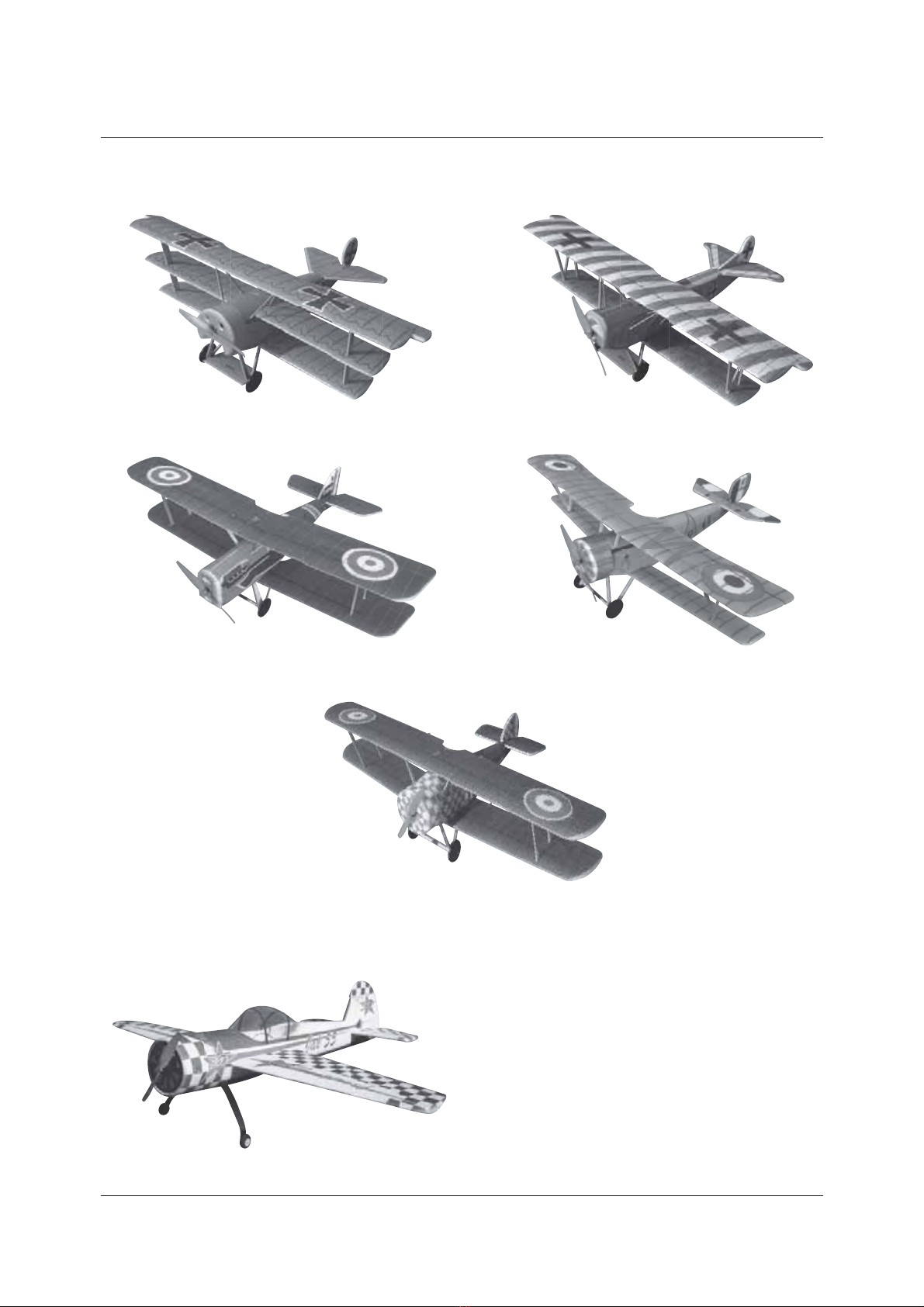
NEW MODELS FROM FLYTEAM
WWI
AEROBAT
Foker Dr.I Foker DVII
Neuiport
Sopwith Camel
Jak-55
Se-5
www.flyteam.skFRE BEE
Table of contents
Other FLYTEAM Toy manuals


Popular Toy manuals by other brands

Hasbro
Hasbro Power Rangers Lightning Collection Mighty Morphin Power... manual

Thames & Kosmos
Thames & Kosmos Aircraft Engineer Story and instructions

Eduard
Eduard Re 2002 S.A. quick start guide

marklin
marklin 45 Series manual

ThinkFun
ThinkFun MakerStudio Windmill Build instructions

Fisher-Price
Fisher-Price W1711 quick start guide


