FLYTEAM Free Bee 50% User manual
Free Bee 50%
Dear customer, congratulations on the purchase of the Free Bee50%model. To enjoy building and flying the model
most, please read carefully the building instructions before you begin and make sure that you understand the building
process.
List of parts
Name pieces Name piece
Half of fuselage from EPP 2 Wing spar (1x1000mm) 1
Control rod 2 Wheels diameter 74mm 2
Wing of EPP 1 Control surface lever 2
Horizontal tail of EPP 1 Tailskid 1
Vertical tail of EPP 1 Elevator joiner 1
CNC-milled fiberglass sheet 2 Dowels for tie rubber loops 2
Upper part of fuselage of EPP 1 Undercarriage axle, 3 x 120 mm 2
Lower part of fuselage of EPP 1 Quick Lock 2
Bulkhead set, 12 pieces 1 Undercarriage rubber loop spring 1
Rudder hinges 2 Building manual 1
Front canopy 1
You will need the following tools and materials:
CA glue, CA glue accelerator, a sharp (modelling) knife.
To complete the model you need the following: a receiver (MZK), two servos (Waypoint W-060), an AC controller
(Robotbirds Pro 10), a battery pack (2 LiPol cells of 600 – 800 mAh), a 60W brushless motor (HCS C 60W/2-3) + 9/5
HD GWS propeller.
Description of the model:
The model is completely made of the expanded polypropylene (EPP), and its design is optimised for easy flying. Its
low weight (about 90 grams) makes it an ideal model for flying in any place – e.g. school playing field or in the street.
It has been designed for not only the experienced pilots, but for the advanced modellers in mind as well. Thanks to its
well thought out design the actual building process would take about 270 minutes.
Model assembly:
All joints should be glued using thin CA glue. In the first phase of work, tack-glue the joints so that they just hold
together; then only after checking their position and symmetry glue permanently. Take care not to let the glue
penetrate the EPP and stick your fingers to the plastic structure. Building the model is not difficult provided you
have an elementary experience with EPP model building. Remember that the EPP has a somewhat “rubbery“
properties, so do not apply force handling and processing it, as stretching or compressing the model parts may
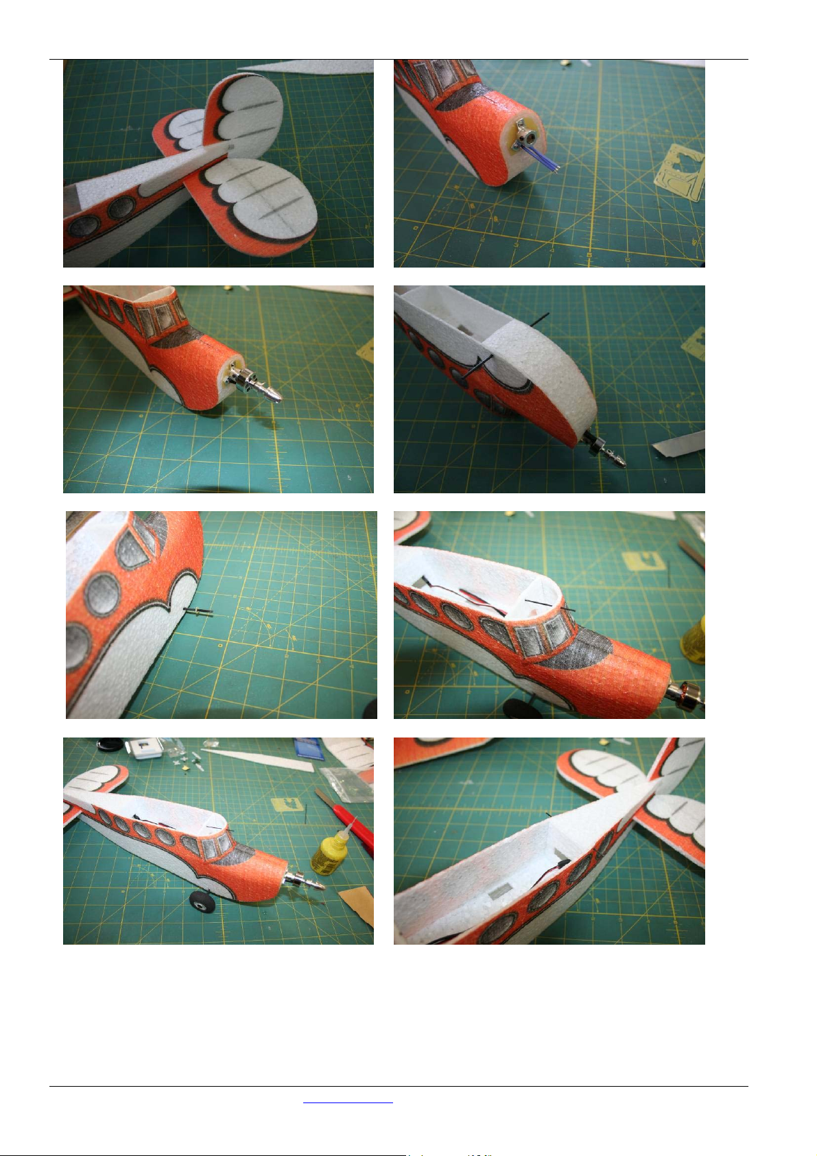
cause their eventual distortion. First glue together the fuselage side panels (Fig.1). After glue has set, bend the side
panels at front and leave weighted for some 20 minutes; that would facilitate handling them and later on and also
gluing of the complete fuselage. Then make the fuselage bulkheads ready, assembling them as per Fig.4. Now glue
the fuselage bulkheads to one of the side panels (Fig. 5). Then glue also the other side panel to the bulkheads.
Prove first, however, that everything is aligned well, then, using a weight, secure the position of the side panel and
thoroughly fill the joints with glue. (Fig. 6). The thin CA glue would flow through the joints not requiring to
disassemble the structure for gluing. After a check that the fuselage is straight and true flow the glue into the joint
of the keel in the front fuselage and glue in place the second part of the keel so that it would seat on the reinforced
front part of the fuselage (Fig. 6). Using several drops of the CA glue, tack the upper part of fuselage in place (Fig.
11), after testing it for alignment, glue it along the full length of side panels (Fig. 22). Now glue the fuselage
lower part in the same way (Fig. 7) only to first bulkhead. Using a sharp knife, cut the canopy part as per Figs.8 If
the canopy fits well, glue it in place (Fig. 9,10). Glue in place the rudder hinges (Fig. 12). Glue the wire joiner to
the elevator (Fig. 13). Now glue the elevator into the fuselage (Fig.14). Using a sharp modelling knife, bevel the
fuselage edges so that the rudder may deflect freely and glue the rudder (Fig. 15) and its arm in place. Using the
sandpaper, sand away any bumps on the fuselage front and glue the motor bearers to the bulkhead (Fig. 16). The
fuselage is designed with the motor downthrust in mind, but ensure that in case of need the motor bearer could be
unbolted and have washers inserted to change the downthrust angle. Connect the motor (Fig. 17). Insert the axle
through the fuselage and secure with CA to bulkhead ( Fig.18). Place the glassfibre end-stop washers in a distance
of some 12 mm from the ends of axle, and carefully glue with CA (Fig. 19). Once the glue cured, slide the
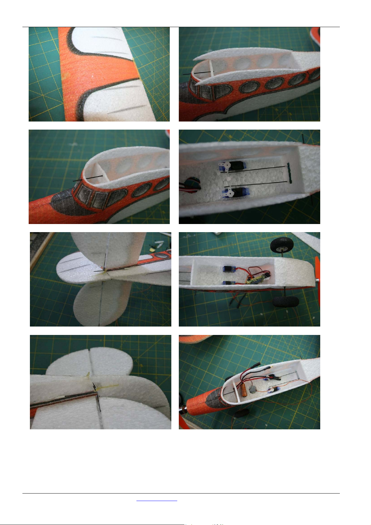
undercarriage wheels on the axle and secure with the QuickLock washer (Fig.21) . Glue the front wing holding
dowel of 1 x30mm carbon rod( Fig. 20). Glue the reinforcement for the rubber loop, fixing the wing to the
fuselage (Fig. 24,25). Push the servos into the prepared openings (Fig. 26) and install control rod. Connect the
servos to the receiver and check the neutral position and the correct spacing of channels. On the empennage side
bend the wire to make an L and using a drop of CA, secure them from accidental sliding out ( if it is
necessary).Check again the alignment of the complete fuselage and glue the fuselage lower part. Glue the rear
Manual FreeBee 50% www.flyteam.sk Page nr..: 1 /
6

Picture
wing-holding dowel of 1 x 50 mm carbon wire (Fig.22). . The Free Bee model is not too sensitive to the position
of the centre of gravity, it should lie, however, some 40-50 mm from the wing leading edge. If you want super
slow fly use underlay bellow the leading edge of the wing to increase angle of wing. Thanks to the excellent flight
characteristics there is no need to limit the control surface deflections. The model is very docile and nice-flying,
yet it is still very nimble and able to be flown in a confined space. The Free Bee is not designed to be flown in
extremely strong winds, yet it handles well the wind velocities of about 3 m/s; only keep in mind the necessity to
have a sufficient spatial reserve so that the model would not be blown away from sight.Many happy moments
with the Free Bee model wishes Flyteam.
01 02
03 04
05 06
Manual FreeBee 50% www.flyteam.sk Page Nr..: 2 / 6

Picture
07 08
09 10
11 12
13 14
Manual FreeBee 50% www.flyteam.sk Page Nr..: 3 / 6
Picture
15 16
17 18
19 20
21 22
Manual FreeBee 50% www.flyteam.sk Page Nr..: 4 / 6
Picture
23 24
25 26
27 28
29 30
Manual FreeBee 50% www.flyteam.sk Page Nr..: 5 / 6

Picture
Obsah stavebnice
Název počet Název počet
Polovina trupu z EPP 2 Kabina 1
Táhla 2 Kola 35mm 2
Křídlo z EPP ( 3 díly) 1 Průchodka táhel 2
Výškové kormidlo z EPP 1 Panty směrového kormidla 2
Směrové kormidlo z EPP 1 Spojka výškovky 1
CNC-frézovaná sada příslušenství 2 Kolík pro upínací gumu křídla 2
Vrchní díl trupu z EPP 1 Osa podvozku, 2 x 95 mm 2
Spodní díl trupu z EPP 1 Quick Lock 2
Sada přepážek, 4 kusy 1 Stavební návod 1
Ke stavběbudeme potřebovat:
CA lepidlo, ostrý nůž . Vybavení modelu dle požadovaných letových vlastnosti pro venkovní létaní –
doporučujeme: střídavý motor 10g ( 2000kv), 2s1p lipol accu pack 300mAh, vhodný regulátor (např. robotbirds
6A), přijímačmin.3 kanálový cca 5g ( MZK Penta). Vrtule 4až5“ (dle motoru) a dvěserva 2,5-5 g (např. Waypoint
W-038). V této konfiguraci má model hmotnost lehce přes 90g. Při použití menšího motoru (5g) ,baterií 200mAh a
použití menšího přijímače a serv se dá hmotnost ještěvíce snížit pro létání na menším prostoru .
Sestavení modelu:
Veškeré spoje lepíme pomocí řídkého vteřinového lepidla. V první fázi spoje jen pojistíme tak, aby držely
u sebe a následněpo kontrole pozice a souměrnosti je zalepíme. Dáváme při tom pozor na to, aby lepidlo
neproteklo skrz EPP a nepřilepili jsme si prsty ke konstrukci. Stavba modelu není obtížná pokud máte základní
zkušenosti se stavbou modelůz EPP. Při lepení dbejte na „gumové“ vlastnosti EPP a snažte se při lepení
nepoužívat sílu, ta může způsobit natažení dílůa jejich následné zkřivení. Nejprve slepíme bočnice trupu (obr.1).
Po zaschnutí lepidla bočnice v přední části přehneme a necháme zatížené cca 20 minut, to nám usnadní
manipulaci s bočnicemi i vlastní lepení trupu. Následněsi připravíme přepážky trupu, které slepíme podle obrázku
č.4. Nyní můžeme k jedné z bočnic přilepit přepážky trupu (obr. 5). Poté přilepíme i druhou bočnici k přepážkám.
Nejprve si zkuste zda je vše kolmé, poté si pomocí vhodného závaží zajistěte pozici bočnice a prolijte spoje
(obr.6). Řídké CA lepidlo proteče do spoje bez nutnosti díly od sebe oddělit. Po kontrole souososti trupu prolijeme
i spoj páteře v přední části trupu a přilepíme druhou část páteře tak, aby seděla na zesílení přední části trupu
(obr.6). Pomocí několika kapek CA přilepíme vrchní díl trupu (obr. 11), po kontrole souososti jej přilepíme po celé
délce bočnic (obr.22). Nyní stejným postupem přilepíme dno trupu (obr. 7), ale jen k části s první přepážkou.
Pomocí nože seřízneme díl kabiny v místech podle obrázku 8. Pokud kabinka pasuje, můžeme ji přilepit (obr.
9,10). Zalepíme panty pro směrové kormidlo (obr. 12). Do výškového kormidla vlepíme spojku z drátu (obr. 13).
Nyní vlepíme výškové kormidlo do trupu (obr.14) Pomocí ostrého nože seřízneme trup tak aby se směrové
kormidlo mohlo volněotáčet a přilepíme směrové kormidlo (obr. 15) i jeho páku. Pomocí brusného papíru obruste
případné nerovnosti v přední části trupu a přilepte motorové lože (obr. 16). Konstrukce trupu již počítá
s potlačením motoru, ale v případěpotřeby počítejte s tím, aby šlo motorové lože odšroubovat a podložit.
Připojíme motor (obr. 17). Provlékneme osu podvozku trupem a zajistíme jí CA lepidlem k přepážce (obr. 18). Ve
vzdálenosti 12mm přilepíme zajišťovací laminátové kolečko podvozku (obr. 19). Nasadíme podvozková kola a
zajistíme je podložkou QuicLock (obr.21) . Přilepíme přední vázací kolík křídla z uhlíku 1x30mm (obr.20)
Obdobněpřilepíme zadní vázací kolík z uhlíku 1x50mm. Ke střední části trupu přilepíme podložku pro křídla (obr.
24,25). Do připravených otvorůvmáčkneme serva (obr. 26) a připojíme táhla kormidel (obr.27). . Serva připojíme
k přijímači a zkontrolujeme neutrální polohy serv a správné rozložení kanálů. Na straněkormidel drát ohneme do
L a pomocí kapky CA vytvoříme zajištění proti vysunutí (pokud je to nutné). Opět kontrolujeme souosost celého
trupu a přilepíme spodní díl. Do trupu vlepíme ostruhu podvozku (obr.29). Model Free Bee není náchylný na
přesné dodržení těžiště, to by mělo být 40-50 mm od náběžné hrany křídla. Pokud budete létat v hale nebo na
menším prostoru doporučujeme použít podložku pod náběžnou hranu křídla pro zvětšení úhlu náběhu. Díky
vynikajícím letovým vlastnostem není nutné omezovat výchylky kormidel. Model je velice obratný na malém
prostoru a přesto poslušný. Model není vhodný do silného větru, ale zvládá let do cca 3m/s, jen dávejte pozor na to
aby jste měli dostatečnou rezervu a model vám proti větru neodcouval.
Mnoho šťastných chvil s modelem Free Bee 50% přeje Flyteam.
Manual FreeBee 50% www.flyteam.sk Page Nr..: 6 / 6
Table of contents
Languages:
Other FLYTEAM Toy manuals


Popular Toy manuals by other brands


Align
Align T-Rex 500CF instruction manual

Carl Goldberg Products
Carl Goldberg Products Hot Stik ARF instructions

Fisher-Price
Fisher-Price LEARNING PATTERNS Fill & Spill Birdies B0004 instructions

ZONE KIZ
ZONE KIZ 347-011V00 manual

Phoenix Model
Phoenix Model SONIC 25 instruction manual

E-FLITE
E-FLITE F86 Sabre 15DF Assembly manual