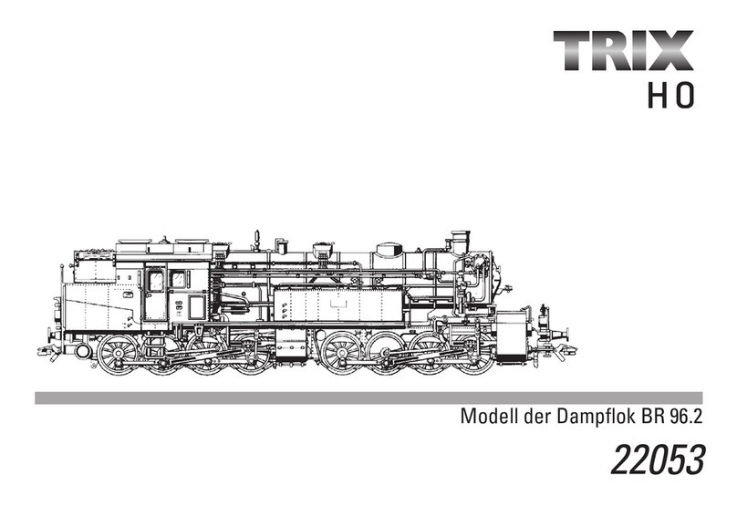
Trix 241 Series User manual

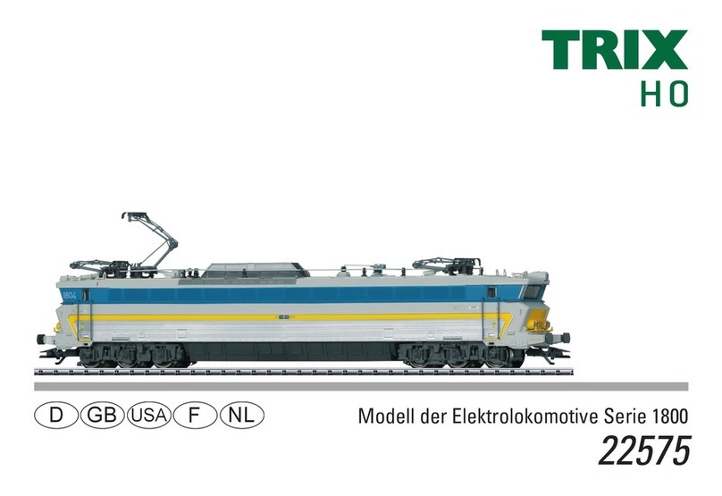
Modell der Schnellzug-Dampflokomotive Serie 241
22941
D GB F
USA NL

2
Verstellbarer Tenderabstand. In Werksauslieferung langer Tenderabstand eingestellt. Zum Verpacken den langen Tenderab-
stand einstellen!
Adjustable tender spacing. The unit comes from the factory with the long tender spacing set. Extend the spacing between the
locomotive and tender to the longest point for packaging purposes.
Ecart entre tender et loco réglable. Ecart réglé à la livraison : long. Réduire l‘écart avec le tender pour l‘emballage!
Afstand tussen loc en tender verstelbaar. Af fabriek is de langere afstand ingesteld. Voor het verpakken de langere tenderaf-
stand instellen!
Click!

3
Inhaltsverzeichnis: Seite
Sicherheitshinweise 4
Wichtige Hinweise 4
Multiprotokollbetrieb 4
Hinweise zum Digitalbetrieb 5
Schaltbare Funktionen 7
Parameter / Register 8
Ergänzendes Zubehör 24
Wartung und Instandhaltung 26
Ersatzteile 32
Table of Contents: Page
Safety Notes 9
Important Notes 9
Multi-Protocol Operation 9
Notes on digital operation 10
Controllable Functions 12
Parameter / Register 13
Completing accessories 24
Service and maintenance 26
Spare Parts 32
Sommaire : Page
Remarques importantes sur la sécurité 14
Information importante 14
Mode multiprotocole 14
Remarques relatives au fonctionnement en mode digital
15
Fonctions commutables 17
Paramètre / Registre 18
Accessoires complémentaires 24
Entretien et maintien 26
Pièces de rechange 32
Inhoudsopgave: Pagina
Veiligheidsvoorschriften 19
Belangrijke aanwijzing 19
Multiprotocolbedrijf 19
Aanwijzingen voor digitale besturing 20
Schakelbare functies 22
Parameter / Register 23
Aanvullende toebehoren 24
Onderhoud en handhaving 26
Onderdelen 32

4
Sicherheitshinweise
• DieLokdarfnurmiteinemdafürbestimmtenBetriebssystem
eingesetzt werden.
• Analogmax.15Volt=,digitalmax.22Volt~.
• DieLokdarfnurauseinerLeistungsquelleversorgtwerden.
• BeachtenSieunbedingtdieSicherheitshinweiseinder
Bedienungsanleitung zu Ihrem Betriebssystem.
• FürdenkonventionellenBetriebderLokmussdasAnschluss-
gleis entstört werden. Dazu ist das Entstörset
611655zuverwenden.FürDigitalbetriebistdasEntstörset
nicht geeignet.
• ACHTUNG! Funktionsbedingte scharfe Kanten und Spitzen.
• SetzenSiedasModellkeinerdirektenSonneneinstrahlung,
starkenTemperaturschwankungenoderhoherLuftfeuchtig-
keit aus.
• VerbauteLED`sentsprechenderLaserklasse1nach
Norm EN 60825-1.
Wichtige Hinweise
• DieBedienungsanleitungunddieVerpackungsindBestand-
teiledesProduktesundmüssendeshalbaufbewahrtsowie
bei Weitergabe des Produktes mitgegeben werden.
• FürReparaturenoderErsatzteilewendenSiesichbittean
Ihren Trix-Fachhändler.
• GewährleistungundGarantiegemäßderbeiliegendenGaran-
tieurkunde.
• Entsorgung:www.maerklin.com/en/imprint.html
• DervolleFunktionsumfangistnurunterDCCunduntermfx
verfügbar.
• Eingebaute,fahrtrichtungsabhängigeStirnbeleuchtung.
Im Digitalbetrieb schaltbar.
• BefahrbarerMindestradius424mm.
Multiprotokollbetrieb
Analogbetrieb
DerDecoderkannauchaufanalogenAnlagenoderGleisab-
schnitten betrieben werden. Der Decoder erkennt die analoge
Gleichspannung(DC)automatischundpasstsichderanalogen
Gleisspannungan.EssindalleFunktionen,dieuntermfxoder
DCCfürdenAnalogbetriebeingestelltwurdenaktiv(siehe
Digitalbetrieb).
Digitalbetrieb
Der Decoder ist ein Multiprotokolldecoder. Der Decoder kann unter
folgenden Digital-Protokollen eingesetzt werden: mfxn DCC oder
MM.
Adresse ab Werk: DCC 03 / MM 41
Das Digital-Protokoll mit den meisten Möglichkeiten ist das
höchstwertige Digital-Protokoll. Die Reihenfolge der Digital-
Protokolle ist in der Wertung fallend:
Priorität 1: mfx
Priorität 2: DCC
Priorität 3: MM
Hinweis: Digital-Protokolle können sich gegenseitig beein-
ussen.FüreinenstörungsfreienBetriebempfehlenwir,nicht
benötigte Digital-Protokolle mit CV 50 zu deaktivieren.
DeaktivierenSie,soferndiesIhreZentraleunterstützt,auchdort
die nicht benötigten Digital-Protokolle.
WerdenzweiodermehrereDigital-ProtokolleamGleiserkannt,

5
übernimmtderDecoderautomatischdashöchstwertigeDigital-
Protokoll,z.B.mfx/DCC,somitwirddasmfx-Digital-Protokollvom
Decoderübernommen.
Hinweis:BeachtenSie,dassnichtalleFunktioneninallen
Digital-Protokollen möglich sind. Unter mfx und DCC können
einigeEinstellungenvonFunktionen,welcheimAnalog-Betrieb
wirksamseinsollen,vorgenommenwerden.
Hinweise zum Digitalbetrieb
• DiegenaueVorgehensweisezumEinstellenderdiversen
Parameter entnehmen Sie bitte der Bedienungsanleitung
Ihrer Mehrzug-Zentrale.
• DieabWerkeingestelltenWertesindfürmfxgewählt,so
dass ein bestmöglichstes Fahrverhalten gewährleistet ist.
FürandereBetriebssystememüssengegebenenfallsAnpas-
sungen getätigt werden.
• DerBetriebmitgegenpoligerGleichspannungimBremsab-
schnitt ist mit der werkseitigen Einstellung nicht möglich. Ist
dieseEigenschaftgewünscht,somussaufdenkonventio-
nellenGleichstrombetriebverzichtetwerden(CV29/Bit2=0).
mfx-Protokoll
Adressierung
• KeineAdresseerforderlich,jederDecodererhälteineeinma-
ligeundeindeutigeKennung(UID).
• DerDecodermeldetsichaneinerCentralStationoderMobile
Station mit seiner UID automatisch an.
• Mfx-TechnologiefürMobileStation/CentralStation.
Name ab Werk: 241-A-65 SNCF
Programmierung
• DieEigenschaftenkönnenüberdiegrascheOberächeder
Central Station bzw. teilweise auch mit der Mobile Station
programmiert werden.
• EskönnenalleCongurationVariablen(CV)mehrfachgele-
sen und programmiert werden.
• DieProgrammierungkannentwederaufdemHaupt-oder
dem Programmiergleis erfolgen.
• DieDefaulteinstellungen(Werkseinstellungen)können
wieder hergestellt werden.
• Funktionsmapping:FunktionenkönnenmitHilfederCentral
Station60212(eingeschränkt)undmitderCentralStation
60213/60214/60215 beliebigen Funktionstasten zugeordnet
werden(SieheHilfeinderCentralStation).
DCC-Protokoll
Adressierung
• KurzeAdresse–LangeAdresse–Traktionsadresse
• Adressbereich:
1-127kurzeAdresse,Traktionsadresse
1 - 10239 lange Adresse
• JedeAdresseistmanuellprogrammierbar.
• KurzeoderlangeAdressewirdüberdieCVsausgewählt.
• EineangewandteTraktionsadressedeaktiviertdieStandard-
Adresse.

6
Programmierung
• DieEigenschaftenkönnenüberdieCongurationsVariablen
(CV)mehrfachgeändertwerden.
• DieCV-NummerunddieCV-Wertewerdendirekteingegeben.
• DieCVskönnenmehrfachgelesenundprogrammiertwerden
(ProgrammierungaufdemProgrammiergleis).
• DieCVskönnenbeliebigprogrammiertwerden(Programmie-
rungaufdemHauptgleisPoM).PoMistnurbeideninderCV-
Tabelle gekennzeichneten CV möglich. Die Programmierung
aufdemHauptgleis(PoM)mussvonIhrerZentraleunterstützt
werden(sieheBedienungsanleitungihresGerätes).
• DieDefaulteinstellungen(Werkseinstellungen)können
wieder hergestellt werden.
• 14bzw.28/126Fahrstufeneinstellbar.
• AutomatischesBremsen(CV27=Wert16)
• AlleFunktionenkönnenentsprechenddemFunktionsmapping
geschaltet werden.
• WeitereInformation,sieheCV-TabelleDCC-Protokoll.
Eswirdempfohlen,dieProgrammierungengrundsätzlichauf
dem Programmiergleis vorzunehmen.
Logische Funktionen
Anfahr-/Bremsverzögerung
• DieBeschleunigungs-undBremszeitkanngetrenntvonei-
nander eingestellt werden.
• DielogischeFunktionsabschaltungABVkannüberdas
Funktionsmapping auf jede beliebige Funktionstaste gelegt
werden.

7
Schaltbare Funktionen
DC/AC
MS I 1
MS II
CS I
CS II/III
Geräusch:Lichtmaschine F19
Geräusch:Lichtmaschine+Spitzensignal F20
Geräusch:Wasserfassen F21
Geräusch:Kohlefassen F22
Geräusch:Sandnachfüllen F23
Geräusch:Sanden F24
Geräusch:Sicherheitsventil F25
Rangierlicht doppel A F26
RangierlichtdoppelA+Rangiergang F27
Geräusch:Kupplungsgeräusch F28
Geräusch:Bahnhofsdurchsage F29
Geräusch:Schaffnerpff F30
Schaltbare Funktionen
DC/AC
MS I 1
MS II
CS I
CS II/III
Spitzensignal F0
Rauchgenerator F1
Betriebsgeräusch F2
Geräusch:Lokpfeifelang F3
ABV,aus F4
Geräusch:Bremsenquietschenaus F5
Führerstandsbeleuchtung F6
Geräusch:Rangierpff F7
Triebwerksbeleuchtung F8
Geräusch:Dampfablassen F9
Geräusch:Kohleschaufeln F10
Geräusch:Kipprost F11
Geräusch:Luftpumpe F12
Geräusch:Wasserpumpe F13
Geräusch:Injektor F14
Geräusch:Ansage F16
Geräusch:Schienenstöße F17
Umgebungsgeräusch: Bahnhof F18 1Trix Systems

8
CV Bedeutung Wert DCC ab Werk
1 Adresse 1 - 127 3
2 PoM Minimalgeschwindigkeit 0 - 255 4
3 PoM Anfahrverzögerung 0 - 255 21
4 PoM Bremsverzögerung 0 - 255 21
5 PoM Maximalgeschwindigkeit 0 - 255 166
8 Werkreset/Herstellerkennung 8 131
13 PoM Funktionen F1 - F8 im Analogbetrieb 0 - 255 1
14 PoM FunktionenF9-F15undLichtimAnalogbetrieb 0 - 255 1
17 ErweiterteAdresse(obererTeil) CV29,Bit5=1 192
18 ErweiterteAdresse(untererTeil) CV29,Bit5=1 128
19 Traktionsadresse 0 - 255 0
21 PoM Funktionen F1 - F8 bei Traktion 0 - 255 0
22 PoM FunktionenF9-F15undLichtbeiTraktion 0 - 255 0
29
Bit 0: Umpolung Fahrtrichtung
Bit 1: Anzahl Fahrstufen 14 oder 28/128
Bit 2: DCC Betrieb mit Bremsstrecke
(keinAnalogbetriebmöglich)
Bit 5: Adressumfang 7 Bit / 14 Bit
0 / 1
0 / 2
0 / 4
0 / 32
***
0,1,2,3,4,5,6,7,
32,34,35,36,37,
38,39
6
63 Lautstärke 0 - 255 255
PoMProgramontheMain;mussvomSteuergerätunterstütztwerden
*** DieWertedergewünschtenEinstellungensindzuaddieren!

9
• Built-inheadlightsthatchangeoverwiththedirectionof
travel. They can be turned on and off in digital operation.
• Minimumradiusforoperationis424mm/16“.
Multi-Protocol Operation
Analog Operation
This decoder can also be operated on analog layouts or areas
of track that are analog. The decoder recognizes alternat-
ingcurrent(DC)andautomaticallyadaptstotheanalogtrack
voltage. All functions that were set under mfx or DCC for analog
operationareactive(seeDigitalOperation).
Digital Operation
The decoders are multi-protocol decoders. These decoders can
beusedunderthefollowingdigitalprotocols:mfx,DCCorMM.
Address set at the factory: DCC 03 / MM 41
The digital protocol with the most possibilities is the highest
order digital protocol. The sequence of digital protocols in
descending order is:
Priority 1: mfx
Priority 2: DCC
Priority 3: MM
Note: Digital protocols can influence each other. For trouble-free
operation,werecommenddeactivatingthosedigitalprotocols
not needed by using CV 50. Deactivate unneeded digital proto-
cols at this CV if your controller supports this function.
Iftwoormoredigitalprotocolsarerecognizedinthetrack,
the decoder automatically takes on the highest order digital
protocol,example:mfx/DCC;thedecodertakesonthemfxdigital
protocol(seeprevioustable).
Safety Notes
• Thislocomotiveisonlytobeusedwiththeoperatingsystem
it is designed for.
• Analogmax.15voltsDC,digitalmax.22voltsAC.
• Thislocomotivemustneverbesuppliedwithpowerfrom
more than one power pack.
• Pleasemakenoteofthesafetynotesintheinstructionsfor
your operating system.
• Thefeedertrackmustbeequippedtopreventinterference
withradioandtelevisionreception,whenthelocomotiveis
to be run in conventional operation. The 611 655 interference
suppression set is to be used for this purpose. The interfe-
rence suppression set is not suitable for digital operation.
• WARNING! Sharp edges and points required for operation.
• Donotexposethemodeltodirectsunlight,extremechanges
intemperature,orhighhumidity.
• TheLEDsinthisitemcorrespondtoLaserClass1according
to Standard EN 60825-1.
Important Notes
• Theoperatinginstructionsandthepackagingareacompo-
nent part of the product and must therefore be kept as well as
transferred along with the product to others.
•
Please see your authorized Trix dealer for repairs or spare parts.
• Thewarrantycardincludedwiththisproductspeciesthe
warranty conditions.
• Disposing:www.maerklin.com/en/imprint.html
• ThefullrangeoffunctionsisonlyavailableunderDCCandmfx.
10
Note: Please note that not all functions are possible in all digital
protocols.Severalsettingsforfunctions,whicharesupposedto
beactiveinanalogoperation,canbedoneundermfxandDCC.
Notes on digital operation
• Theoperatinginstructionsforyourcentralunitwillgiveyou
exact procedures for setting the different parameters.
• Thevaluessetatthefactoryhavebeenselectedformfxin
order to guarantee the best possible running characteristics.
Adjustments may have to be made for other operating
systems.
• Thesettingdoneatthefactorydoesnotpermitoperationwith
opposite polarity DC power in the braking block. If you want
thischaracteristic,youmustdowithoutconventionalDC
poweroperation(CV29/Bit2=0).
mfx Protocol
Addresses
• Noaddressisrequired;eachdecoderisgivenaone-time,
uniqueidentier(UID).
• ThedecoderautomaticallyregistersitselfonaCentralStation
or a Mobile Station with its UID.
• MfxtechnologyfortheMobileStation/CentralStation.
Name set at the factory: 241-A-65 SNCF
Programming
• Thecharacteristicscanbeprogrammedusingthegraphic
screen on the Central Station or also partially with the Mobile
Station.
• AlloftheCongurationVariables(CV)canbereadand
programmed repeatedly.
• Theprogrammingcanbedoneeitheronthemaintrackorthe
programming track.
• Thedefaultsettings(factorysettings)canbeproduced
repeatedly.
• Functionmapping:Functionscanbeassignedtoanyofthe
function buttons with the help of the 60212 Central Station
(withlimitations)andwiththe60213/60214/60215CentralSta-
tion(SeehelpsectionintheCentralStation).
DCC Protocol
Addresses
• Shortaddress–longaddress–multipleunitaddress
• Addressrange:
1-127forshortaddressandmultipleunitaddress,
1 - 10239 for long address
• Everyaddresscanbeprogrammedmanually.
• AshortoralongaddressisselectedusingtheCVs.
• Amultipleunitaddressthatisbeinguseddeactivatesthe
standard address.

11
Programming
• Thecharacteristicscanbechangedrepeatedlyusingthe
CongurationVariables(CV).
• TheCVnumbersandtheCVvaluesareentereddirectly.
• TheCVscanbereadandprogrammedrepeatedly.(Program-
mingisdoneontheprogrammingtrack.)
• TheCVscanbeprogrammedinanyorderdesired.(Program-
mingcanbedoneonthemaintrackPoM).ThePoMcanonly
be done with those designated in the CV table. Programming
on the main track PoM must be supported by your central
controller(Pleaseseethedescriptionforthisunit.).
• Thedefaultsettings(factorysettings)canbeproduced
repeatedly.
• 14/28or126speedlevelscanbeset.
• Allofthefunctionscanbecontrolledaccordingtothefunc-
tionmapping(seeCVdescription).
• SeetheCVdescriptionfortheDCCprotocolforadditional
information.
We recommend that in general programming should be done on
the programming track.
Logic Functions
Acceleration/Braking Delay
• Theaccelerationandbrakingtimecanbesetseparatelyfrom
each other.
• ThelogicfunctionABVcanbeassignedtoanyfunction
button by using the function mapping.

12
Controllable Functions
DC/AC
MS I 1
MS II
CS I
CS II/III
Soundeffect:Generator F19
Soundeffect:Generator+Headlights F20
Sound effect: Filling water F21
Sound effect: Filling coal F22
Sound effect: Filling sand F23
Sound effect: Sanding F24
Sound effect: Safety valve F25
Double A switching light F26
DoubleAswitchinglight+Lowspeed
switching range F27
Sound effect: Sounds of couplers F28
Sound effect: Station announcement F29
Sound effect: Conductor whistle F30
Controllable Functions
DC/AC
MS I 1
MS II
CS I
CS II/III
Headlights F0
Smoke generator F1
Operating sounds F2
Soundeffect:Longlocomotivewhistle F3
ABV,off F4
Sound effect: Squealing brakes off F5
Engineer‘s cab lighting F6
Sound effect: Switching whistle F7
Running gear lights F8
Sound effect: Blowing off steam F9
Sound effect: Coal being shoveled F10
Sound effect: Ash grate F11
Sound effect: Air pump F12
Sound effect: Water pump F13
Sound effect: Injector F14
Sound effect: Announcement F16
Sound effect: Rail joints F17
Background sound: Station F18 1Trix Systems

13
PoM Program on the Main; must be supported by the controller
*** The values for the desired settings must be added.
CV Discription DCC Value Factory-Set
1 Address 1 - 127 3
2 PoM Minimum Speed 0 - 255 4
3 PoM Acceleration delay 0 - 255 21
4 PoM Braking delay 0 - 255 21
5 PoM Maximum speed 0 - 255 166
8 Factory Reset / Manufacturer Recognition 8 131
13 PoM Functions F1 - F8 in analog operation 0 - 255 1
14 PoM Functions F9 - F15 and lights in analog operation 0 - 255 1
17 Extendedaddress(upperpart) CV29,Bit5=1 192
18 Extendedaddress(lowerpart) CV29,Bit5=1 128
19 Multiple Unit Address 0 - 255 0
21 PoM Functions F1 - F8 on Multiple Unit 0 - 255 0
22 PoM Functions F9 - F15 and lights on Multiple Unit 0 - 255 0
29
Bit 0: Reversing direction
Bit 1: Number of speed levels 14 or 28/128
Bit 2: DCC operation with braking area
(noanalogoperationpossible)
Bit 5: Address length 7 Bit / 14 Bit
0 / 1
0 / 2
0 / 4
0 / 32
***
0,1,2,3,4,5,6,7,
32,34,35,36,37,
38,39
6
63 Volume 0 - 255 255

14
Remarques importantes sur la sécurité
• Lalocomotivenepeutêtreutiliséequ‘aveclesystème
d‘exploitation indiqué.
• Analogiquemax.15Volt=,digitalmax.22Volt~.
• Lalocomotivenepeutpasêtrealimentéeélectriquementpar
plus d‘une source de courant à la fois.
• Ilestimpératifdetenircomptedesremarquessurla
sécurité décrites dans le mode d‘emploi de votre système
d‘exploitation.
•
Pourl’exploitationdelalocomotiveenmodeconventionnel,la
voiederaccordementdoitêtredéparasitée.Aceteffet,utili-
serlesetdedéparasitageréf.611655.Lesetdedéparasitage
ne convient pas pour l’exploitation en mode numérique.
•
ATTENTION! Pointes et bords coupants lors du fonctionnement
du produit.
• Nepasexposerlemodèleàunensoleillementdirect,àde
fortes variations de température ou à un taux d‘humidité
important.
• LesDELinstalléescorrespondentàlaclasselaser1selonla
norme EN 60825-1.
Information importante
• Lanoticed‘utilisationetl’emballagefontpartieintégrantedu
produit;ilsdoiventdoncêtreconservéset,lecaséchéant,
transmis avec le produit.
• Pourtouteréparationouremplacementdepièces,adressez
vous à votre détaillant-spécialiste Trix.
• Garantielégaleetgarantiecontractuelleconformémentau
certicatdegarantieci-joint.
• Elimination:www.maerklin.com/en/imprint.html
• L’intégralitédesfonctionsestdisponibleuniquementen
exploitation DCC et mfx.
• Feuxdesignalisations‘inversantselonlesensdemarche;
feux commutables en exploitation digital.
• Rayonminimald’inscriptionencourbe424mm.
Mode multiprotocole
Mode analogique
On peut aussi faire fonctionner le décodeur sur des installations
oudessectionsdevoieanalogiques.Ledécodeuridentie
automatiquementlatensiondevoieanalogique(CC).Toutesles
fonctions qui ont été paramétrée pour le mode analogique sous
mfxousousDCCsontactives(voirmodenumérique).
Mode numérique
Lesdécodeursontdesdécodeurmultiprotocole.Ledécodeur
peutêtreutiliséaveclesprotocolesnumériquessuivants:mfx,
DCC,MM.
Adresse encodée en usine: DCC 03 / MM 41
Leprotocolenumériqueoffrantlespossibilitéslesplus
nombreusesestleprotocolenumériqueàbitdepoidsfort.La
hiérarchisation des protocoles numériques est descendante :
Priorité 1 : mfx
Priorité 2 : DCC
Priorité 3 :
MM
Indication : des protocoles numériques peuvent s’influencer
réciproquement.Pouruneexploitationsansperturbations,
nous recommandons de désactiver avec CV 50 des protocoles
numériques non nécessaires.
Danslamesureoùvotrecentralelessupporte,désactivezy

15
aussi les protocoles numériques non nécessaires.
Lorsquedeuxouplusieursprotocolesnumériquessontidentiés
auniveaudelavoie,ledécodeurreprendautomatiquement
leprotocolenumériqueàbitdepoidsfort,p.ex.mfx/DCC.Le
protocolenumériquemfxestdoncreprisparledécodeur(voir
tableauantérieur).
Indication : remarquez que toutes les fonctions ne peuvent
pasêtreactionnéesdanstouslesprotocolesnumériques.
SousmfxetsousDCC,ilestpossibledeprocéderàquelques
paramétragesdefonctionsdevantêtreactivesdanslecadrede
l’exploitation analogique.
Remarques relatives au fonctionnement en mode
digital
• Encequiconcernelaprocédurederéglagedesdivers
paramètres,veuillezvousréféreraumoded‘emploidevotre
centrale de commande multitrain.
• Lesvaleursparamétréesd’usinesontchoisiespourmfxde
manière à garantir le meilleur comportement de roulement
possible.
Pourd’autressystèmesd’exploitation,cesvaleursdevront
éventuellementêtreadaptées.
• Lesvaleursparamétréesd’usinesontchoisiesdemanièreà
garantir le meilleur comportement de roulement possible.
• L’exploitationaveccourantcontinudepolaritéinversedans
les sections de freinage n’est pas possible avec le réglage
d’usine.Sicettepropriétéestdésirée,ilfautalorsrenoncerà
l’exploitation conventionnelle en courant continu
(CV29/Bit2=0).
Protocole mfx
Adressage
• Aucuneadressen’estnécessaire,ledécodeurreçoittoute-
foisuneidenticationuniqueetnonéquivoque(UID).
• AvecsonUID,ledécodeurindiqueautomatiquementàune
station centrale ou à une station mobile qu’il est connecté.
• TechnologiemfxpourMobileStation/CentralStation.
Nom encodée en usine : 241-A-65 SNCF
Programmation
• Lescaractéristiquespeuventêtreprogramméesparl’inter-
médiairedelacouchegraphiquedelastationcentrale,voire
en partie aussi au moyen de la station mobile.
• Touteslescongurationsvariables(CV)peuventêtrelueset
programméesdefaçonréitérée.
• Laprogrammationpeutêtreréaliséesoitsurlavoieprinci-
pale,soitsurlavoiedeprogrammation.
• Lesparamétragespardéfaut(paramétragesusine)peuvent
êtrerétablis.
• Mappagedesfonctions:lesfonctionspeuventêtreaffectées
à de quelconques touches de fonction au moyen de la station
centrale(60212)(restreinte)etaveclastationcentrale
60213/60214/60215(voirAideauniveaudelastationcentrale).

16
Protocole DCC
Adressage
• Adressebrève–adresselongue–adressedetraction.
• Champd’adresse:
1–127adressebrève,adressedetraction
1–10239adresselongue
• Chaqueadresseestprogrammablemanuellement.
• L’adressebrèveoulongueestchoisieparl’intermédiairedesCVs.
• Uneadressedetractionutiliséedésactivel’adressestandard.
Programmation
•
Lescaractéristiquespeuventêtremodiéesdefaçonréitérée
parl’intermédiairedesvariablesdeconguration(CVs).
• Touteslescongurationsvariables(CV)peuventêtrelueset
programméesdefaçonréitérée.
• Laprogrammationpeutêtreréaliséesoitsurlavoieprinci-
pale,soitsurlavoiedeprogrammation.
• LesCVspeuventêtreprogramméeslibrement(programma-
tiondelavoieprincipale(PoM).LaPoMn’estpossibleque
pourlesCVsidentiéesdansletableaudesCVs.Laprogram-
mationsurlavoieprincipale(PoM)doitêtresupportéepar
votrecentrale(voirmoded’emploidevotreappareil).
• Lesparamétragespardéfaut(paramétragesusine)peuvent
êtrerétablis.
• 14/28,voire126cransdemarchesontparamétrables.
• Touteslesfonctionspeuventêtrecommutéesenfonctiondu
mappagedesfonctions(voirledescriptifdesCVs).
• Pourtouteinformationcomplémentaire,voirletableaudes
CVs,protocoleDCC.
Ilestrecommandé,deréaliserlaprogrammation,fondamentale-
ment,surlavoiedeprogrammation.
Fonctions logiques
Retard au démarrage / au freinage
• Lestempsd’accélérationetdefreinagepeuventêtreparamé-
trés séparément les uns des autres.
• Parl’intermédiairedumappagedesfonctions,lamisehors
fonctiondelafonctionlogiqueABVpeutêtreaffectéeà
n’importe quelle touche de fonction.

17
Fonctions commutables
DC/AC
MS I 1
MS II
CS I
CS II/III
Bruitage : Dynamo d‘éclairage F19
Bruitage:Dynamod‘éclairage+Fanal
éclairage F20
Bruitage : Approvisionnement en eau F21
Bruitage : Approvisionnement en charbon F22
Bruitage : Approvisionnement en sable F23
Bruitage : Sablage F24
Bruitage : Soupape de sûreté F25
Feu de manœuvre double A F26
FeudemanœuvredoubleA+Vitessede
manœuvre F27
Bruitage : Bruit d’attelage F28
Bruitage : Annonce en gare F29
Bruitage : Sifflet Contrôleur F30
Fonctions commutables
DC/AC
MS I 1
MS II
CS I
CS II/III
Fanal F0
Générateurdefumée F1
Bruit d’exploitation F2
Bruitage : Sifflet locomotive long F3
ABV,désactivé F4
Bruitage:Grincementdefreinsdésactivé F5
Eclairage de la cabine de conduite F6
Bruitage : Sifflet pour manœuvre F7
Eclairage du mécanisme moteur F8
Bruitage : Échappement de la vapeur F9
Bruitage : Pelletage du charbon F10
Bruitage:Grillebasculante F11
Bruitage : Compresseur F12
Bruitage : Pompe à eau F13
Bruitage : Injecteur F14
Bruitage : Annonce F16
Bruitage : joints de rail F17
Bruitageambiant:Gare F18 1Trix Systems

18
PoMProgramontheMain;doitêtreprisenchargeparl’appareildecommande
*** Lesvaleursdesréglagesdésiréssontàadditioner.
CV Affection DCC Valeur Parm. Usine
1 Adresse 1 - 127 3
2 PoM Vitesse min 0 - 255 4
3 PoM Temporisation d‘accélération 0 - 255 21
4 PoM Temporisation de freinage 0 - 255 21
5 PoM Vitesse maximale 0 - 255 166
8Réinitialisationd’usine/identicationdufabricant 8 131
13 PoM Fonctions F1 - F8 en mode analog 0 - 255 1
14 PoM Fonctions F9 - F15 et éclairage en mode analog 0 - 255 1
17 Adresseétendue(partiesupérieure) CV29,Bit5=1 192
18 Adresseétendue(partieinférieure) CV29,Bit5=1 128
19 Adresse traction 0 - 255 0
21 PoM Fonctions F1 - F8 pour traction 0 - 255 0
22 PoM Fonctions F9 - F15 et éclairage traction 0 - 255 0
29
Bit 0: Inv. polarité Sens de marche
Bit 1: Nombre de crans de marche 14 ou 28/128
Bit 2:
ModeDCCavecdist.defreinage(modeanalogimpossible)
Bit 5: Capacité d’adresses 7 Bit / 14 Bit
0 / 1
0 / 2
0 / 4
0 / 32
***
0,1,2,3,4,5,6,7,
32,34,35,36,37,
38,39
6
63 Volume 0 - 255 255

19
Veiligheidsvoorschriften
• Delocmagalleenmeteendaarvoorbestemdbedrijfssysteem
gebruikt worden.
• Analoogmax.15Volt=,digitaalmax.22Volt~.
• Delocmagnietvanuitmeerdanéénstroomvoorziening
gelijktijdig gevoed worden.
• Leesookaandachtigdeveiligheidsvoorschrifteninde
gebruiksaanwijzing van uw bedrijfssysteem.
• Voorhetconventionelebedrijfmetdelocdientdeaansluitrail
te worden ontstoort. Hiervoor dient men de ontstoor-set 611
655 te gebruiken. Voor het digitale bedrijf is deze ontstoor-set
niet geschikt.
• OPGEPAST! Functionele scherpe kanten en punten.
• Stelhetmodelnietblootaanindirectezonnestraling,sterke
temperatuurwisselingen of hoge luchtvochtigheid.
• IngebouwdeLED’skomenovereenmetdelaserklasse1
volgens de norm EN 60825-1.
Belangrijke aanwijzing
• Degebruiksaanwijzingendeverpakkingzijneenbestanddeel
van het product en dienen derhalve bewaard en meegeleverd
te worden bij het doorgeven van het product.
• VoorreparatiesenonderdelenkuntzichtotUwTrixhandelaar
wenden.
• Vrijwaringengarantieovereenkomstighetbijgevoegde
garantiebewijs.
• Afdanken:www.maerklin.com/en/imprint.html
• Devolledigetoegangtotallefunctiesisalleenmogelijkmet
DCC of met mfx bedrijf.
• Ingebouwde,rijrichtingsafhankelijkefrontverlichtingisinhet
digitaalsysteem schakelbaar.
• Minimaleteberijdenradius:424mm.
Multiprotocolbedrijf
Analoogbedrijf
De decoder kan ook op analoge modelbanen of spoortrajecten
gebruikt worden. De decoder herkent de analoge gelijkspanning
(DC)automatischenpastzichaandeanalogerailspanningaan.
Alle functies die onder mfx of DCC voor het analoge bedrijf zijn
ingesteld,wordengeactiveerd(ziedigitaalbedrijf).
Digitaalbedrijf
De Decoder is een multiprotocoldecoder. De decoder kan onder
devolgendedigitaleprotocolleningezetworden:mfx,DCC,MM.
Vanaf de fabriek ingesteld: DCC 03 / MM 41
Het digitaalprotocol met de meeste mogelijkheden is het pri-
maire digitaalprotocol. De volgorde van de digitaalprotocollen is
afnemend in mogelijkheden:
Prioriteit 1: mfx
Prioriteit 2: DCC
Prioriteit 3: MM
Opmerking: de digitale protocollen kunnen elkaar beïnvloe-
den. Voor een storingsvrij bedrijf is het aan te bevelen de niet
gebruikte protocollen met CV 50 te deactiveren. Deactiveer
eveneens,voorzoveruwcentraleditondersteunt,ookdedaar
niet gebruikte digitale protocollen.
Wordentweeofmeerdigitaalprotocollenopderailsherkend,
dan neemt de decoder automatisch het protocol met de hoogste
prioriteit,bijv.mfx/DCC,danwordtdoordedecoderhetmfx-
digitaalprotocolgebruikt(ziebovenstaandoverzicht).

20
Opmerking: let er op dat niet alle functies in alle digitaal-
protocollen mogelijk zijn. Onder mfx of DCC kunnen enkele
instellingen,welkeinanaloogbedrijfwerkzaammoetenzijn,
ingesteld worden.
Aanwijzingen voor digitale besturing
• Hetopdejuistewijzeinstellenvandediverseparameters
staat beschreven in de handleiding van uw digitale Centrale.
• Fabrieksmatigzijndewaardenvoormfxzoingesteltdat
optimale rijeigenschappen gegarandeerd zijn.
Voor andere bedrijfssystemen moeten eventueel aanpassin-
gen uitgevoerd worden.
• Devanafdefabriekingesteldewaardenzijnzoingestelddat
de rij-eigenschappen optimaal zijn.
• Hetbedrijfmettegengepooldegelijkspanningindeafrem-
sectie is met de fabrieksinstelling niet mogelijk. Indien deze
eigenschapwenselijkis,danmoetwordenafgezienvanhet
conventioneelgelijkstroombedrijf(CV29/Bit2=0).
Mfx-protocol
Adressering
• Eenadresisnietnodig,elkedecoderheefteenéénmaligen
éénduidigkenmerk(UID).
• DedecodermeldtzichvanzelfaanbijhetCentralStationof
Mobile Station met zijn UID.
• Mfx-technologievoorhetMobileStation/CentralStation.
Naam af de fabriek: 241-A-65 SNCF
Programmering
• Deeigenschappenkunnenm.b.v.hetgrascheschermop
het Central Station resp. deels ook met het Mobile Station
geprogrammeerd worden.
• Alleconguratievariabelen(CV)kunnenvakergelezenen
geprogrammeerd worden.
• Deprogrammeringkanzowelophethoofdspooralsophet
programmeerspoor gebeuren.
• Dedefault-instellingen(fabrieksinstelling)kunnenweer
hersteld worden.
• Functiemapping:functieskunnenmetbehulpvanhetCentral
Station60212(metbeperking)enmethetCentralStation
60213/60214/60215 aan elke gewenste functietoets worden
toegewezen(ziehethelpbestandinhetCentralStation).
DCC-protocol
Adressering
• Kortadres–langadres–tractieadres
• Adresbereik:
1–127kortadres,tractieadres
1–10239langadres
• Elkadresishandmatigprogrammeerbaar.
• KortoflangadreswordtviadeCVgekozen.
• Eentoegepasttractieadresdeactiveerthetstandaardadres.
This manual suits for next models
1
Table of contents
Languages:
Other Trix Toy manuals

Trix
Trix Minitrix BR98.7 User manual

Trix
Trix B VI User manual

Trix
Trix Minitrix 11629 User manual

Trix
Trix BB 15000 Series User manual

Trix
Trix BR 23 User manual

Trix
Trix Minitrix BR 54 User manual

Trix
Trix BR 58 User manual

Trix
Trix BR 218 User manual

Trix
Trix Be 6/8III Series User manual

Trix
Trix Ub User manual
Popular Toy manuals by other brands

Clas Ohlson
Clas Ohlson HK-TF2144A manual

Nexa
Nexa AGWAGON C188 instruction manual

SCALE-PARKFLYER
SCALE-PARKFLYER Mustang B Fatty Building instructions

MGA Entertainment
MGA Entertainment Secret Crush Baking Oven manual

Calico Craft Parts
Calico Craft Parts GARGOYLE Assembly instructions

Lionel
Lionel F3 A-B-A Diesel owner's manual