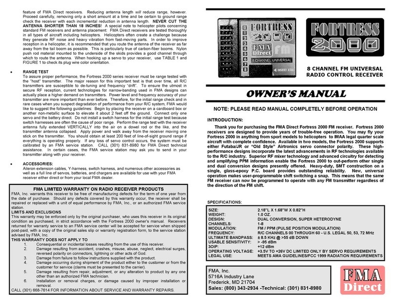
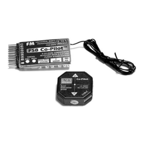
FMA Direct FS5 User manual

4
FMA limited warranty for receivers
FMA, Inc. warrants this product to be free of manufacturing defects for the term of one year from the date of
purchase. Should any defects covered by this warranty occur, the product shall be repaired or replaced with a
unit of equal performance by FMA or an authorized FMA service station.
Limits and exclusions
This warranty may be enforced only by the original purchaser, who uses this product in its original condition as
purchased, in strict accordance with the product’s instructions. Units returned for warranty service to an FMA
service center will be accepted for service when shipped postpaid, with a copy of the original sales receipt or
warranty registration form, to the service station designated by FMA.
This warranty does not apply to:
Consequential or incidental losses resulting from the use of this product.
Damage resulting from accident, misuse, abuse, neglect, electrical surges, reversed polarity on connectors,
lightning or other acts of God.
Damage from failure to follow instructions supplied with the product.
Damage occurring during shipment of the product either to the customer or from the customer for service
(claims must be presented to the carrier).
Damage resulting from repair, adjustment, or any alteration of the product by anyone other than an authorized
FMA technician.
Installation or removal charges, or damage caused by improper installation or removal.
Call (301) 668-7614 for more information about service and warranty repairs.
FS Receiver button summary
Button functions in Setup Mode
Do this... And this happens...
Press and hold button, turn on receiver Receiver enters Setup Mode (LED “twinkles”).
Servos set for Last Frame Mode move slowly,
servos set for Failsafe Mode move to failsafe
positions (and don't move after that).
Move transmitter stick(s) to servo failsafe position
for channel(s), press button, return transmitter
stick(s) to neutral (or low for throttle)
Receiver sets servo to failsafe position(s) for
channel(s). For mixed channels, this sets
failsafe positions for all channels in mix.
Press and hold button for 2 seconds Receiver sets all channels to Last Frame Hold
Mode (this erases Failsafe Mode servo presets
on all channels).
Button functions in Normal Flight Mode
Do this... And this happens...
Don’t press button LED blinks number of failsafes (up to 9) since receiver was turned on. No
blinks = perfect signal.
Press button 1 time LED blinks battery voltage (each long blink = 1V, each short blink = 0.1V).
Press button 3 times LED blinks number of bad frames (up to 99) since receiver was turned on
(each long blink = 10 bad frames, each short blink = 1 bad frame). (Less
than 30 bad frames indicates very clean signal during typical flight.)
Press button 5 times Change between 1X and 2X LED blink rate
(1X = 1 blink/second, 2X = 2 blinks/second).
Tip:
When checking for bad frames or changing blink rate, make each press before LED turns on.
FMA, Inc.
5716A Industry Lane
Frederick, MD 21704
Sales: (800) 343-2934
Technical: (301) 668-7614
www.fmadirect.com
Flight System
FS5 Receiver for Aircraft
Features
Protect your investment before you take off, while you’re flying, and after you land.
Universal operation: works with negative shift (Futaba, Hitec) and positive shift (JR, Airtron-
ics) PPM transmitters. For aircraft (72MHz) installations.
Full range, full performance. Can be used in aircraft ranging from park flyers to IMAA-legal
aircraft to helicopters.
Interference check tells you if it’s safe to fly. Detects both on- and off-channel interference.
Digital Signal Recognition eliminates nearly all interference.
Better range checking: receiver records signal loss (if any) during check, then displays result.
Set any channel for a failsafe position using your transmitter. On loss of signal, failsafe chan-
nels move to preset positions, other channels hold last good frame position.
LED blinks battery voltage, number of failsafes and number of bad frames received.
Viewer Software provides real-time display and analysis of receiver operation and setup.
Note:
This manual provides basic instructions. More informa-
tion is available to help you use the receiver:
Online help file for FS Receiver Viewer Software.
FS Receiver and Viewer Software manual in PDF (download
from the Support section at www.fmadirect.com).
Safety precautions
Follow all instructions in this manual to assure safe operation.
If you have not assembled and operated a radio controlled model before, obtain help from an
experienced modeler. You will need guidance to successfully assemble, test and operate radio
controlled models. One of the best ways to obtain help is to join your local radio control club.
In some areas of the country, you cannot legally operate radio controlled models except at
approved fields. Check with local authorities first.
Observe frequency control. If someone else is operating a radio controlled model on the same
channel as your transmitter,
do not turn on your transmitter—even for a short time.
Your
transmitter has a channel number marked somewhere on its case.
When a model receives
signals from two transmitters on the same channel at the same time, it cannot be con-
trolled and will crash—possibly causing personal injury or property damage.
For safety,
most RC flying fields have formal frequency control rules. Follow them carefully.
Do not operate your radio control transmitter within 3 miles of a flying field. Even at a dis-
tance, your transmitter can cause interference.
Parts list
FS Receiver.
Viewer Software CD (see
separate instructions; not
required for setting up and
operating the receiver).
You must supply:
Crystal: FMA Quantum or Fortress series dual conversion or
Hitec dual conversion (on same channel as your transmitter).
Battery pack: typically 4 or 5 cell NiCd. (Do not use alkaline
batteries!)
Radio on/off switch harness.
Servos.
User Guide Version 1.29 Rev 1

2
Installing the FS Receiver
Tip:
Servos, aileron extension cables, switch harnesses, Y-harnesses, battery packs, chargers and
many other accessories are available from your local FMA dealer or from FMA Direct (www.fma.com).
1. Plug in crystal and servos. Servo chan-
nel 1 is farthest from crystal. Black or
brown wires on connectors go toward
outside. Plug battery/switch harness
into any unused channel, or use Y har-
ness to connect battery and servo to one
channel. (
Do not use “old style,” pre-
“Z-type” Airtronics servo connectors.
)
Failure to observe correct servo/
battery polarity voids warranty.
Damage may result to both receiver and servos.
2.
Optional, but recommended:
External Switch/LED Module (part number FSRES1, available
separately) lets you interact with receiver from outside aircraft. Mount module in holes in
fuselage, then plug it into receiver on pins between button and crystal (white wire toward servo
connectors).
3. Wrap receiver in foam rubber and secure in aircraft.
Failure to protect receiver voids war-
ranty.
4. Route antenna. Do not coil antenna, as this substantially reduces range. You may cut antenna
to as short as 18" without de-tuning the receiver. However, range will be reduced. Be sure to
range test and cut off a little bit at a time until antenna reaches desired length.
About the FS Receiver
How it works.
Unlike most receivers, when the FS Receiver detects bad frames, it moves the
servos to the last known position or moves them to failsafe positions you preset, depending on the
mode you set for each channel.
FS Receiver Error Detection
learns about the transmitter sending
signals to the receiver. It determines the transmitter type (positive or negative shift) and number
of channels. When the receiver detects bad frames for about 1 second, it takes over control of the
servos. This is called a
failsafe
.
The FS Receiver has extensive error correcting ability to clean up the PPM signal. Additionally,
the receiver continuously performs 20 internal checks for memory and I/O problems. After low
voltage brownouts, it restores operating parameters without locking up.
Modes:
In
Last Frame Hold Mode
, the FS Receiver maintains the servo positions in the last valid
frame from the transmitter. As delivered from the factory, all channels are set to Last Frame
Hold Mode. You can also reset the receiver to this state at any time.
In
Failsafe Mode
, loss of valid frames (for about 1 second) moves some or all the servos to
positions you preset: all channels with failsafe positions move to their preset positions, while
channels without failsafe positions stay where they are (as in Last Frame Hold Mode).
In
Setup Mode
, you tell the FS Receiver what to do when it receives bad frames. You can set
any channel to move to a preset position during Failsafe Mode. Channels not set up for Fail-
safe Mode remain in Last Frame Hold Mode. The receiver stores setup information, and keeps
it even when power is turned off.
Normal Flight Mode
is the receiver’s regular operating mode. Use Normal Flight Mode for
testing, range checking and flying your aircraft. If the receiver detects invalid frames, it auto-
matically applies Last Frame Hold or Failsafe presets to each channel. When valid frames are
again received, the FS Receiver returns to Normal Flight Mode.
FS Receiver
Pin 1 (black or brown)
Channel 1
LED Button
Crystal socket White
Connect Ext. Switch/LED Module here
Red wire
Antenna
3
Setting up and using the FS Receiver
Setting up the receiver
1. Enter Setup Mode: Turn on transmitter,
press and hold receiver button while turning on re-
ceiver
. LED “twinkles” in Setup Mode. Servos set for Last Frame Mode move slowly, servos
set for Failsafe Mode move to failsafe positions (and don't move after that).
2. Set a channel for Failsafe Mode: Move transmitter stick to desired failsafe position, press
receiver button, return stick to neutral (or idle) before LED turns on. Repeat for other chan-
nels. Channels in a mix are set at the same time. If not set for Failsafe Mode, channel is auto-
matically in Last Frame Hold Mode.
Best failsafe preset servo positions depend on your particular aircraft and how it behaves in the
air. A reasonable starting point for flight-stable, non-aerobatic airplanes is:
Ailerons: neutral.
Rudder: moderate right turn.
Elevator: neutral.
Throttle: 1/3 to 1/2.
Test these settings and adjust them as needed. Goal is to have plane circle and gently descend,
without stalling, during a failsafe condition.
3. Leave Setup Mode: Turn receiver off. Receiver retains settings even when power is off.
Checking radio system range: initial test and troubleshooting procedure
(Because the FS Receiver corrects for occasional glitches, you can't check range by watching for
jittering servos or control surfaces.)
1. Place receiver on a non-metallic surface (e.g., cardboard box) to elevate it about 2 feet (60cm)
off the ground. Fully extend receiver antenna and position it vertically above receiver (tape
antenna to a wooden dowel, for example). Connect one servo to receiver channel 1.
2. Fully collapse transmitter antenna. Turn on transmitter.
3. Connect a battery pack directly to receiver. Do not use a switch harness for this test, since a
switch harness may reduce range.
4. Walk away from receiver about 200 feet (60m) while moving channel 1 transmitter stick.
5. KEEPING TRANSMITTER ON, return to model and watch
receiver LED:
If LED is still continuously on: there were no failures, and the
receiver remained under your control during the range test.
If LED is blinking, range is less than 200 feet (60m).
6. Disconnect receiver from battery, then turn off transmitter.
Checking failsafe operation on the ground
1. Turn on transmitter, turn on receiver.
2. Turn off transmitter. Receiver moves servos to failsafe/last frame positions.
3. Turn on transmitter. Receiver LED blinks, indicating a failsafe occurred.
Using the receiver
To check for interference:
Turn on receiver (leave your transmitter off). LED is on for 2 sec-
onds to confirm power, then: LED off = no interference, or blinking = interference is present.
To check battery voltage:
While moving transmitter sticks (to load system), press receiver
button 1 time, then count LED blinks (long blink = 1 volt, short blink = 0.1 volt).
Fly normally. If receiver loses signal, servos go to failsafe presets or stay at last good position.
Optional:
After flight, keep transmitter and receiver on to review radio system performance:
If LED is blinking, number of blinks = number of failsafes during flight.
Press receiver button 3 times, count LED blinks to determine number of bad frames during
flight (long blink = 10 frames, short blink = 1 frame). Less than 30 bad frames = very clean
signal during flight. (Use Viewer Software Help Wizard after flight for more receiver data.)
Note:
If, under these conditions, the
radio system experiences failures,
there may be a problem with the
transmitter, the FS Receiver or
another part of the radio system. If
you suspect the transmitter is out of
tune, FMA can tune it for you. With
proof of purchase for an FMA
receiver, FMA will tune your transmit-
ter (any brand) at no charge. The
only cost is for shipping.
Other FMA Direct Receiver manuals
