FMA Direct Co-Pilot FS8 User manual

FS8 Co-Pilot™
Advanced Radio Control Receiver System
featuring
Digital Signature Recognition,
Failsafe Operation,
Infrared Flight Stabilization
and Full Telemetry
User’s Guide
FMA, Inc.
5716A Industry Lane
Frederick, MD 21704
Sales: (800) 343-2934 lTechnical: (301) 668-4280
www.fmadirect.com
Note: Read this manual carefully before using FS8 Co-Pilot™.

FS8 Co-Pilot™ user guide 2FMA Direct
About FS8 Co-Pilot™
FS8 Co-Pilot™ combines a high-performance failsafe receiver
with infrared flight stabilization.
Built-in receiver
nInterference Check, which determines the presence of a trans-
mitter operating on your channel, as well as interference from
any source on any frequency that affects receiver operation.
nDigital Signature Recognition, a new technology that enables
FS8 Co-Pilot™ to reject severe interference and to recon-
struct corrupted frames.
nServo Failsafe, which enables FS8 Co-Pilot™ to take control
of the aircraft when a signal isn’t present.
nSystem status and performance data output, which provides
information about how your radio system operated during
range checks and flights.
nUniversal operation: works with negative shift (Futaba, Hitec)
and positive shift (JR, Airtronics) FM PPM transmitters.
nFull range, full performance. Can be used in aircraft ranging
from park flyers to IMAA-legal aircraft to helicopters.
Built-in flight stabilization
nControls roll and pitch for any kind of RC aircraft: conven-
tional fixed wing airplanes, flying wings, electric powered
planes, giant scale models and helicopters. Returns aircraft to
level attitude when you center the transmitter sticks.
nInfrared sensors operate in nearly all weather conditions.
nLearns about your transmitter and its controls. Setup is easy
because there are no switches to set.
nCan be turned on and off, and adjusted, from your transmitter
via an assigned channel.
nCan be automatically activated when receiver enters Failsafe
Mode.
nWorks with optional Vertical Sensor:
lFlight stabilization knows when the aircraft is inverted.
lEnables full 3D aerobatics display in the Co-Pilot Viewer
software during playback from the optional Flight Re-
corder.
lSimplifies daily field calibration for large aircraft.
Other features
nWorks with your FM PPM transmitter, or your PCM transmit-
ter set to PPM.
nWorks with all aircraft configurations, including dual aileron
servos, quad flaps, elevons, V-tail, complex transmitter mixes,
digital servos and CCPM.
nIncludes Co-Pilot Viewer Software for detailed receiver and
flight stabilization data analysis. Displays every FS8 Co-Pi-
lot™ operating detail. (Requires Serial Interface Module,
available separately, and a Windows 98 or later PC.)
nCompatible with FS Flight Recorder (available separately),
which records receiver and flight stabilization data during
multiple flights (up to 97 minutes total). Download data from
the Recorder, then play back using Co-Pilot Viewer Software.
About failsafe operation
In the event of signal loss or overwhelming interference, the re-
ceiver takes control of the servos, and puts the aircraft into a pre-
dictable flight pattern. Each servo channel can be set to apply
one of two options when corrective action is required:
nLast Good Frame Hold. If the receiver concludes that a
transmitter frame is defective—and cannot be repaired—it
pulls the last good frame from memory and applies it to the
servos in place of the defective frame. The receiver continues
applying the last good frame until it once again detects a clean
frame. Random glitches, which show up as servo jitter, are
the most common signal problem in radio control systems.
By repairing bad frames or (in the worst case) using the last
good frame, FS8 Co-Pilot™ eliminates nearly all servo jitter.
nServo Failsafe Preset Positions. This option goes one step
further than Last Good Frame Hold by proactively moving
servos to positions set by the pilot during radio system setup.
Servo Failsafe Preset Positions, for example, can cut the
throttle and put the plane into a gentle circle. Any channel in
FS8 Co-Pilot™ can have a Servo Failsafe Preset Position.
Setting Failsafe Preset Positions is easy—your transmitter is
the interface for the procedure.
Introduction
Note: FS8 Co-Pilot™ is a unique product—it’s
quite different from other radio control equipment
you may have used. Since new concepts are in-
volved, take your time and work through the manual
carefully.
© 2003 FMA, Inc. All rights reserved. Reproduction of this publication is prohibited. Co-Pilot is a trademark of FMA, Inc. user guide version 1.10
U.S. Patent 6,181,989. Foreign and other patents pending. 12/26/2003

FMA Direct 3FS8 Co-Pilot™ user guide
About flight stabilization
FS8 Co-Pilot™ “looks” at the horizon with infrared heat sensors
(this same technology is used in thermal imaging cameras). The
Earth is warm (even when covered with snow) below the hori-
zon, while the sky is cold above the horizon. FS8 Co-Pilot™
“sees” this temperature difference. When FS8 Co-Pilot™ senses
changes in aircraft attitude relative to the infrared horizon, it
sends corrective signals to keep the aircraft level.
Flying with FS8 Co-Pilot™ is easy. When you center the control
stick, FS8 Co-Pilot™ automatically returns the aircraft to level
flight. FS8 Co-Pilot™ works over a wide range of weather con-
ditions. A simple calibration adjusts FS8 Co-Pilot™ to the local
environment, and sensitivity controls change FS8 Co-Pilot’s re-
sponses to match pilot skills.
FS8 Co-Pilot™ is an excellent teaching aid because it maintains
stable flight while the student develops flying skills (the key is to
center the sticks to regain control). Advanced pilots find FS8
Co-Pilot™ is useful for flying—and landing—under windy con-
ditions. Because it responds much faster than you can, FS8 Co-
Pilot™ can help tame an unstable aircraft, and is ideal for main-
taining control during your first flights with a new model.
If your transmitter has an unused channel, you can control FS8
Co-Pilot™ from the ground. Turn it on when it’s needed, and
turn it off when it isn’t needed. If the channel has proportional
control, you can also remotely adjust FS8 Co-Pilot’s Pitch and
Roll Throw controls.
FS8 Co-Pilot™ uses patented technology to sense the difference
in infrared temperature (heat) between the Earth and sky. The
sky is always at a relatively lower infrared temperature, while the
infrared signature of the Earth is always relatively warmer. FS8
Co-Pilot™ uses two pairs of infrared sensors: one pair points
fore and aft, and the other points left and right. When one pair
of sensors sees a change in an aircraft’s orientation relative to
the earth’s infrared horizon, FS8 Co-Pilot™ issues signals to the
control system to bring the aircraft back into level flight.
When the model is flying above the Earth (even a few feet), each
sensor surveys several square miles, all the way to the Earth’s in-
frared horizon. The infrared temperature seen for the Earth is an
average of infrared generated from all terrain features. FS8 Co-
Pilot™ interprets input from the sensors and applies compensa-
tion to the servos controlling roll and pitch.
Other optical flight stabilization systems work with visible light,
not infrared. Those systems are strongly affected by changes in
cloud cover and other weather conditions, and don’t operate well
at sunrise, dusk or in the dark. The heat (infrared) radiating
from the Earth measured by FS8 Co-Pilot™ provides a more
stable and precise reference than light or other phenomena. This
gives FS8 Co-Pilot™ much more precision than visible light sta-
bilization systems. For example, FS8 Co-Pilot™ won’t cause
the aircraft to wander when a cloud comes into view.
Since the infrared environment is not affected by variations in
visible light levels, an airplane equipped with FS8 Co-Pilot™
could be flown at night (but we don’t recommend this!). Only
substantial changes in weather cause gradual variations in infra-
red temperature throughout a day. Heavy fog, flying through
clouds, or snow on the ground cause the infrared signature to
vary. Also, as a model flies over the terrain, there is some varia-
tion in the average infrared temperature. For this reason, FS8
Co-Pilot™ incorporates a simple calibration procedure (not
available in other flight stabilizers) that fine-tunes performance
for near-perfect stabilization under all conditions.
Options for controlling flight stabilization
FS8 Co-Pilot™ can be controlled in three different ways. The
methods available to you depend on the capabilities of your ra-
dio control system.
nProportional control. If your radio system has an unused
proportional control channel (usually a knob or lever on the
transmitter), it can be assigned to turn FS8 Co-Pilot™ on and
off, and to adjust sensitivity during flight. You’ll be able to
set sensitivity between minimum and maximum—based on
flight conditions or desired performance—at any time.
Examples of proportional control:
lAdjust FS8 Co-Pilot™ sensitivity while the model is air-
borne to match a student’s skills. As the student gains con-
fidence, for instance, set FS8 Co-Pilot™ to provide less
stabilization.
lTurn FS8 Co-Pilot™ off for aerobatics, then turn it on for
landing.
lIf a strong crosswind builds up after the aircraft takes off,
dial in more stabilization for better control during landing.
When configured according to instructions in “Setting up,”
the transmitter knob works like this:
Minimum
throw
Maximum
throw
Flight
stabilization
off
Flight
stabilization
on
nOn/off control. If your radio system has an on/off channel
(usually a switch on the transmitter), you can turn FS8 Co-Pi-
lot™ on and off during flights. When FS8 Co-Pilot™ is on,
its flight stabilization characteristics are set by the Pitch and
Roll Throw controls on the receiver (you can only change this
setting when the aircraft is on the ground). When FS8 Co-Pi-
lot™ is off, the aircraft functions as it would without a flight
stabilization system (although FS8 Co-Pilot™ still trims the
aircraft).
With on/off control, it’s much easier and quicker to move a
switch (versus rotating a knob to the right spot with propor-
tional control). This makes it easier to move between aerobat-
ics (without FS8 Co-Pilot™) and straight/level flight (with
FS8 Co-Pilot™).
continued

FS8 Co-Pilot™ user guide 4FMA Direct
Examples of on/off control:
lAn instructor can take off and trim an airplane with FS8
Co-Pilot™ off, then turn it on when giving control to a stu-
dent.
lYou might use stabilization for most flying, then turn it off
for aerobatics or inverted flight, and turn it back on again
for landing.
nManual control. If your radio system doesn’t have any un-
used channels, FS8 Co-Pilot™ is always on during a flight.
Its flight stabilization characteristics are fixed by the Pitch
and Roll Throw controls on the receiver. To change sensitiv-
ity, you must land the aircraft and manually adjust the Pitch
and Roll Throw controls.
Regardless of the option you select, your experience and skill
will determine how to best use FS8 Co-Pilot™. It is recom-
mended that you turn off FS8 Co-Pilot™ before attempting un-
usual attitudes (for example, inverted flight).
FS8 Co-Pilot™ specifications
Operating voltage +3.5 to +9 volts DC
Operating current <10 milliamps (servos may draw
more current from rapid movement
and stabilization)
Weight With Button/LED Module, supplied
cables and optional Vertical Sen-
sor: 1.9 oz.
With Button/LED Module and sup-
plied cables: 1.8 oz.
Leveling response time 1/60th second
Drift from level <2° (infrared calibration must be
performed)
Flying conditions Day and night; all weather condi-
tions (rain, fog, sleet and snow
may degrade performance)
Humidity Sensor is sealed; keep windows
clean
Remote activation On/off control or proportional throw
adjustment, depending on channel
availability of radio system
Aircraft types Works with all aircraft configura-
tions, including dual aileron ser-
vos, quad flaps, elevons, V-tail,
complex transmitter mixes, digital
servos and CCPM

FMA Direct 5FS8 Co-Pilot™ user guide
Safety precautions
General safety precautions
Radio controlled models are not toys! Please observe these gen-
eral safety precautions:
nFollow all instructions in this manual to assure safe operation.
nIf you have not assembled and operated a radio controlled
model before, obtain help from an experienced modeler. You
will need guidance to successfully assemble, test and operate
radio controlled models. One of the best ways to obtain help
is to join your local radio control club.
nNever fly radio controlled aircraft near people, buildings, tele-
phone or power lines, cars, trees or other objects on the
ground or in the air.
nNever allow a helicopter to fly within 20 feet of you or an-
other person. If a helicopter flies toward you or another per-
son, stop the engine immediately to prevent personal injury.
nKeep your radio controlled models and equipment away from
children. Do not allow unauthorized people of any age to op-
erate radio controlled models without proper supervision from
an experienced modeler.
nIn some areas of the country, you cannot legally operate radio
controlled models except at approved fields. Check with lo-
cal authorities first.
nObserve frequency control. If someone else is operating a ra-
dio controlled model on the same channel as your transmitter,
do not turn on your transmitter—even for a short time.
Your transmitter has a channel number marked somewhere on
its case. When a model receives signals from two transmitters
on the same channel at the same time, it cannot be controlled
and will crash—possibly causing personal injury or property
damage. For safety, most RC flying fields have formal fre-
quency control rules. Follow them carefully.
nDo not operate your radio control transmitter within 3 miles
of a flying field. Even at a distance, your transmitter can
cause interference.
nDo not operate radio controlled models and equipment in the
rain, or at night.
nProtect all electronic equipment from exposure to rain, water,
high humidity and high temperatures.
nFMA Direct recommends that you join the AMA. They can
help you find a club in your area.
Academy of Model Aeronautics
5161 East Memorial Drive
Muncie, Indiana 47302
Phone: (800) 435-9262
Web: www.modelaircraft.org
Safety precautions for flight stabilization:
nFS8 Co-Pilot™ is designed for flight stabilization only. It
cannot navigate the aircraft or prevent a stall. You must con-
trol the aircraft’s flight path.
nFS8 Co-Pilot™ is for recreational use only. Do not install
Co-Pilot™ in aerial photographic aircraft where there is a
possibility of flying over people.
nYou must mount the FS8 Co-Pilot™ Sensor securely. Care-
fully follow the instructions in “Installing,” which tells you to
roughen the surface with sandpaper, then clean the surface
with rubbing alcohol.
nKeep fuel off the Sensors. Fuel on the Sensors can affect FS8
Co-Pilot™ operation for as long as 10 minutes.
nPerform an infrared calibration at the beginning of each flying
session, and repeat the calibration if there are major weather
changes. Details are in “At the field.”
nBesides your regular preflight check, also check FS8 Co-Pi-
lot™ operation before each flight. Details are in “At the
field.”
nFS8 Co-Pilot™ derives precision and flexibility from the cali-
bration procedure (“Infrared calibration” in “At the field”).
Background information and technical reasoning are provided
in “Understanding infrared field calibration” (page 15) and
“About infrared field calibration” (page 16). Please read and
observe the following guidelines for the best, safest operation
with the greatest margin:
lAs nearly as possible, calibrate FS8 Co-Pilot™ over the
type of terrain the aircraft will be flying over. For example,
do not calibrate over bare dirt if the aircraft will be flying
over light vegetation.
lGrass provides the best, most consistent reference terrain,
but snow is the coolest reference terrain.
lIf the flying area has variable terrain, calibrate over the
coolest part. This provides a conservative, lower calibra-
tion number, and assures a greater margin over warmer ref-
erence terrain. Typical infrared temperatures, in order from
coolest to warmest are: snow, water, grass, light vegetation,
sand, and asphalt or concrete.
lIf you calibrate over an artificially warm medium such as
asphalt or concrete, the infrared temperature over anything
else will be lower, which reduces the temperature differ-
ence (between earth and sky) available for FS8 Co-Pilot™
to work with. If at all possible, don’t calibrate over asphalt
or concrete.
lIf the aircraft will be flying over patchy snow, calibrate
over the snow.
lA calibration reading of 1 is rare. It is recommended that
you not fly using FS8 Co-Pilot™ when a reading of 1 is ob-
tained over the coolest terrain present. To completely turn
off FS8 Co-Pilot™, you must rotate the Throw controls
fully counterclockwise or unplug the Roll/Pitch Sensor.
lHelicopters require extra precision to hover. For that rea-
son, you should only use FS8 Co-Pilot™ on a helicopter
when the calibration reading is 3 or greater.

FS8 Co-Pilot™ user guide 6FMA Direct
Parts list
¨FS8 Co-Pilot™ ¨Ribbon cable
¨Pitch/Roll Sensor ¨Velcro®
¨Button and LED Module with cable and nameplate
Ribbon cable Velcro®
Button/LED Module FS8 Co-Pilot™
and Nameplate Pitch/Roll Sensor
Optional components
¨Vertical Sensor with ribbon cable
(Part no. FS8ZS)
¨Low Profile Button/LED
Module for helicopters
(Part no. FS8HS1)
¨Serial Interface Module
(Part no. FSIM1)
¨FS Flight Recorder
(Part no. FSFR1)
Other items you may need
nElevon Mixer (Part no. MX80). Use an on-board elevon
mixer for aircraft with elevons (such as flying wings), when
your radio control transmitter doesn’t provide elevon mixing.
n12" (30cm) flat ribbon cable (Part no. 2MMFRC4P2X12)
18" (46cm) flat ribbon cable (Part no. 2MMFRC4P2X18)
24" (61cm) flat ribbon cable (Part no. 2MMFRC4P2X24)
40" (102cm) flat ribbon cable (Part no. 2MMFRC4P2X40)
l
Longer cables enable the Co-Pilot™ Sensor to be positioned
properly on engine-powered conventional aircraft having
large wingspans (see “Installing Co-Pilot™” for details).
lShorter cables reduce weight on smaller aircraft.
Please measure to determine the correct ribbon cable
length for your aircraft!
nAdvanced Servo Buffer (Part no. 605SB). Strongly recom-
mended for aircraft with long servo extensions and/or gasoline
engines. Works with analog and digital servos. See page 10
for more information.
Before you start
Failsafe and light stabilization work with, and require, a
completely installed and correctly operating aircraft radio
control system: transmitter, FS8 Co-Pilot™, battery pack
and servos. (An airplane with elevons may also need an
on-board mixer, if mixing isn’t provided in the transmitter.)
Before you work with failsafe settings and flight stabiliza-
tion, install and set up your entire radio system. Be abso-
lutely certain the radio system operates correctly—and
moves the control surfaces in the proper directions—be-
fore you get into FS8 Co-Pilot™ set up procedures.
Finally, read and understand the safety precautions on
page 5.
Install
Mount the Roll/Pitch Sensor
nIf you are installing FS8 Co-Pilot™ on an airplane, go to
“Mount the Pitch/Roll Sensor on an airplane.”
nIf you are installing FS8 Co-Pilot™ on a helicopter, go to
“Mount the Pitch/Roll Sensor on a helicopter.”
Mount the Pitch/Roll Sensor on an airplane
1. Locate a mounting spot for the Pitch/Roll Sensor, following
these guidelines:
nPitch/Roll Sensor should be level during flight (a slight tilt
caused by mounting the sensor on a wing with dihedral is
acceptable).
nThe Pitch/Roll Sensor should have a clear view of the hori-
zon on all sides.
nThe Pitch/Roll Sensor must be away from muffler and ex-
haust spray (exhaust spray will cloud the sensor’s infrared
windows and degrade flight stabilization).
nOn a high wing airplane, mount the sensor on top of the
wing about halfway between root and tip ribs, at about
maximum airfoil thickness, on the side away from the ex-
haust.
continued
Front of
airplane

FMA Direct 7FS8 Co-Pilot™ user guide
nOn a low wing airplane with side or top exhaust, mount the
sensor on the bottom of the wing about halfway between
root and tip ribs, at about maximum airfoil thickness, on
the side away from the muffler.
Tip: You can mount the sensor on the bottom of
the fuselage, so its ribbon cable can remain at-
tached, even when you remove the wing. Don’t do
this, however, if the engine exhausts below the fu-
selage.
nOn a low or mid wing airplane with bottom exhaust, mount
the sensor on top of the fuselage, behind the canopy.
Rotate the sensor 45° as shown below. (A clear canopy ap-
pears opaque to the infrared sensors, and will block their
view of the horizon.)
2. Use sandpaper to roughen the surface where the Pitch/Roll
Sensor will be mounted. Clean the roughened area with rub-
bing alcohol and allow to dry.
3. Clean the bottom of the Pitch/Roll Sensor with rubbing alco-
hol and allow to dry.
4. Attach a 1¼" piece of “stiff” Velcro® to the roughened area
on the aircraft.
5. Attach a 1¼" piece of “fuzzy” Velcro® to the bottom of the
Pitch/Roll Sensor.
WARNING: You must mount the Sensor securely,
so it won’t come loose in flight. If it comes loose,
you may lose control of the aircraft. Other mounting
methods can be used, as long as the Sensor re-
mains securely in place during all flight conditions.
6. Mount the Pitch/Roll Sensor in the following orientation:
nWhen mounted on an airplane’s wing or fuselage, and there
is a clear view of the horizon in all directions, one sensor
window should face directly forward, like this:
nWhen mounted behind an airplane’s canopy, two sensors
should be angled 45° from the airplane’s center line, like
this:
nOrient the cable socket so the cable will route neatly into
the radio compartment.
Note: The direction of the “P” arrows (not shown in
the above illustrations) on the Pitch/Roll Sensor is
not critical. However, the sensor must remain in the
same orientation throughout setup, calibration and
flying.
7. IMPORTANT: Carefully remove the protective stickers
from the four sensor windows.
Go to “Mount the optional Vertical Sensor.” Æ
continued
Front of
airplane

FS8 Co-Pilot™ user guide 8FMA Direct
Mount the Pitch/Roll Sensor on a helicopter
1. Attach two pieces of double-sided adhesive tape to the top
and bottom of the boom behind the swashplate. Do not use
Velcro®.
2. Place the Sensor on the top piece of tape with the cable socket
facing forward and the windows angled 45° from the
helicopter’s centerline. The Sensor must be horizontal when
the helicopter is sitting on its skids. Secure the Sensor to the
boom with a cable tie.
WARNING: You must mount the Sensor securely,
so it won’t come loose in flight. If it comes loose,
you may lose control of the aircraft.
3.IMPORTANT: Carefully remove the protective stickers
from the four sensor windows.
Go to “Mount the optional Vertical Sensor.” Æ
Mount the optional Vertical Sensor
The Vertical (“Z”) Sensor enables the flight stabilization system
to determine when the airplane is inverted (so the aircraft rolls
out from inverted, rather than performing a half loop). A giant
scale airplane will need the Vertical Sensor because it can’t be
easily moved into position (nose straight down or one wing
straight down) on the ground for infrared calibration.
nIf you want to use the Vertical Sensor, continue in this section.
nIf you don’t want to use the Vertical Sensor, go to “Mount the
Button/LED Module.”
1. Locate a mounting spot for the Vertical Sensor (typically on
side of the fuselage or helicopter cockpit) Follow these
guidelines:
nThe windows on the Vertical Sensor must point directly up
and down when the airplane is in straight and level flight.
nThe lower window on the Vertical Sensor must have a clear
view of the ground. The upper window must have a clear
view of the sky.
nThe sensor must be away from the muffler and exhaust
spray (exhaust spray will cloud the sensor’s infrared win-
dows and degrade calibration).
nHelicopter blades will not affect the sensor’s view.
2. Use sandpaper to roughen the surface where the Vertical Sen-
sor will be mounted. Clean the roughened area with rubbing
alcohol and allow to dry.
3. Clean the bottom of the Vertical Sensor with rubbing alcohol
and allow to dry.
4. Attach a 1¼" piece of “stiff” Velcro® to the roughened area
on the aircraft.
5. Attach a 1¼" piece of “fuzzy” Velcro® to the side of the Sen-
sor marked “Mount this side to fuselage.”
WARNING: You must mount the Sensor securely,
so it won’t come loose in flight. If it comes loose,
you may lose control of the aircraft. Other mounting
methods can be used, as long as the Sensor re-
mains securely in place during all flight conditions.
6. Mount the Sensor with the arrow pointing directly up when
the airplane is in a straight and level attitude.
UP
MOUNT
THIS
SIDETO
FUSELAGE
Up
7. IMPORTANT: Carefully remove the protective stickers
from the two sensor windows.
Go to “Mount the Button/LED Module.” Æ

FMA Direct 9FS8 Co-Pilot™ user guide
Mount the Button/LED Module
The Button/LED Module enables you to interact with FS8 Co-
Pilot™. You press buttons to tell FS8 Co-Pilot™ what to do,
and you read information from the LED.
IMPORTANT: Don’t just dangle the Button/LED
Module outside the fuselage. Mount it securely
where you won’t accidentally bump it when you are
preparing the aircraft for lift-off or hand launching.
When pressed for 1 second, calibration begins—
and you don’t want to do that when the aircraft is
about to fly.
Follow the instructions below for your specific installation.
Mount the Button/LED Module on an airplane
1. Select a spot to mount the Module. It should be convenient to
press the buttons, and you must be able to see the LED.
2. Drill three holes in the airplane fuselage or helicopter cockpit.
3. Pull off the red caps from the button shafts.
4. Remove the nuts from the buttons, then remove the name-
plate.
5. Insert the buttons and LED into the holes from inside the fuse-
lage or cockpit.
6. Place the nameplate over the buttons and LED.
7. Thread the nuts onto the buttons to secure the Module.
8. Push the red caps onto the button shafts.
Go to “Connect the components.” Æ
Mount the optional Low Profile Button/LED
Module on a helicopter
1. Select a spot to mount the Module. It should be convenient to
press the buttons, and you must be able to see the LED.
2. Attach the Module using two cable ties through the holes in
the PC board.
Note: The Low Profile Button/LED Module is laid
out and marked differently than the standard name-
plate. When you see “REC Button” and “CAL But-
ton” in this manual, substitute “R” and “C” on the
Low Profile Module.
Same as REC Button Same as CAL Button
Go to “Connect the components.” Æ
Connect the components
1. Install the Pitch/Roll Sensor cable:
a. Plug one end of a ribbon cable into the socket in the Pitch/
Roll Sensor (be sure to line up the tab on the connector
with the slot on the socket).
b. Route the Pitch/Roll Sensor cable toward the radio com-
partment. Make certain the cable doesn’t cover a sensor
window.
2. Install the Vertical Sensor cable (if you are using the Vertical
Sensor):
a. Plug one end of the other ribbon cable into the socket in the
Vertical Sensor (be sure to line up the tab on the connector
with the slot on the socket).
b. Route the Vertical Sensor cable toward the radio compart-
ment.
3. Secure the sensor cables:
nFor a conventional airplane: Clean more spots. Secure the
cables with Velcro, tape or flat cable clamps, as shown in
this example:
nFor a flying wing: Secure the cables with tape.
nFor a helicopter: Secure the cables with small cable ties, as
shown in this example:
continued

FS8 Co-Pilot™ user guide 10 FMA Direct
Advanced ServoBuffer
Servoorservoextension
connected topinson bumpyside
ofbuffer
Receiver
4. Insert an FMA receiver crystal in FS8 Co-Pilot’s crystal
socket.
ROLL PITCH
Roll throwadjust
Pitchthrowadjust
Pitch/Roll Sensorcable
VerticalSensorcable
Button/LEDModulecable
AntennaCrystal
Telemetry/Battery
Channel1
FSCo-Pilot
(componentside)
Channel8
Note: This diagram shows FS8 Co-Pilot™ from the
component side of the circuit board (away from the
label). You can also use the label to identify com-
ponent locations and pins.
5. Set the Throw controls:
nIf you will be controlling flight stabilization with a propor-
tional (knob or slider) channel: Turn both Throw controls
fully clockwise.
nIf you will be controlling flight stabilization with an on/off
(switch) channel...
or
If you won’t be controlling flight stabilization from the
transmitter: Set both Throw controls as shown in the dia-
gram below.
Full manualcontrol
Noflightstabilization
30%
Forexpertpilots
50%
Forintermediatepilots
100%
Forbeginning pilots
(butdon’tflyinverted!)
6. Connect the servos to FS8 Co-Pilot™, according to the chan-
nel assignments in your transmitter. If you are using an
onboard elevon mixer (required for flying wings), follow its
instructions to connect it inline with two servos.
Label
Black orbrownwireCrystal
Note: Black or brown wires on servo/battery con-
nectors go away from label side of receiver. (Do
not use “old style,” pre-”Z-type” Airtronics servo
connectors.) Failure to observe correct servo/bat-
tery polarity voids warranty. Damage may result to
both receiver and servos.
7. Plug the Pitch/Roll Sensor cable into FS8 Co-Pilot™.
8. Plug the Vertical Sensor cable into FS8 Co-Pilot™.
9. Plug the Button/LED Module into FS8 Co-Pilot™.
10. Connect the switch harness to FS8 Co-Pilot™.
11. Connect the receiver battery to the switch harness. If you
aren’t installing the FS Flight Recorder, you can connect the
switch harness to the Telemetry/Battery pins on FS8 Co-Pi-
lot™.
12. Wrap FS8 Co-Pilot™ in 3/8" or 1/2" foam rubber to protect
it from vibration.
Note: Failure to use foam rubber to protect FS8
Co-Pilot™ will void your warranty.
13. Place FS8 Co-Pilot™ in the fuselage (or helicopter) and se-
cure it to prevent movement.
Tip: For electric aircraft, keep FS8 Co-Pilot™ at
least 1" away from the motor and battery power
wires, as these radiate RF noise.
14. Route the antenna so it is fully extended. Do not coil an-
tenna, as this substantially reduces range.
Note: You may cut antenna to as short as 18" with-
out de-tuning the receiver. However, range will be
reduced. Be sure to range test and cut off a little bit
at a time until antenna reaches desired length.
Go to “Set up the system.” Æ
continued
Special installation considerations
For large aircraft with long servo extensions, or for any air-
craft powered by a gasoline engine, FMA recommends in-
stalling the Advanced Servo Buffer (Part no. 605SB). For
use with analog and digital servos, this device:
nFilters out electromagnetic interference generated by gas
engine ignition systems.
nFilters out RF interference picked up by long servo wires.
Typical symptoms include multiple failsafes during flights,
erratic servo movement or receiver “swamping.” The Ad-
vanced Servo Buffer is 100% effective in eliminating these
problems.
1. Connect the servo wire to the pins toward the bumpy
side of the Advanced Servo Buffer.
2. Connect the Advanced Servo Buffer cable to the appro-
priate pins on the FS8 Co-Pilot™.

FMA Direct 11 FS8 Co-Pilot™ user guide
Set up the system
Setting up FS8 Co-Pilot™ has three parts:
nSet up failsafe operation, in which FS8 Co-Pilot™ learns
which channels you want assigned as failsafe channels and the
servo failsafe positions for those channels.
nSet up flight stabilization, in which FS8 Co-Pilot™ learns
which channels are assigned to pitch, roll and remote on/off.
nSet Auto Trim, in which you set Auto Trim on or off.
Once FS8 Co-Pilot™ is set up, you normally don’t need to re-
peat the set up unless you change the aircraft’s configuration or
move FS8 Co-Pilot™ to another aircraft.
Tip: If you have a PC and the optional Serial Inter-
face Module, consider setting up FS8 Co-Pilot™
with help from the FS Co-Pilot™ Viewer Software.
The software isn’t required for setup, but its graphi-
cal displays will help you understand what the re-
ceiver is doing. Instructions for installing and run-
ning the software are provided in the FS Co-Pilot™
Viewer Software user guide.
Set up failsafe operation
About receiver modes
As long as power is applied, FS8 Co-Pilot™ keeps servo outputs
energized. Unlike most receivers, when FS8 Co-Pilot™ detects
bad transmitter data, it takes action to put the aircraft in a pre-
dictable flight path.
nNormal Flight Mode is the regular operating mode. Use
Normal Flight Mode for testing, range checking and flying
your aircraft. If FS8 Co-Pilot™ receives statistically bad
frames for about 1 second, it enters...
nFailsafe Mode, in which...
lServos set for Last Good Frame Hold remain in the posi-
tions specified in the last valid frame from the transmitter.
As delivered from the factory, all channels are set for Last
Good Frame Hold. You can also reset the receiver to this
state at any time.
lServos set for Failsafe move to positions you preset.
When FS8 Co-Pilot™ detects good transmitter data, the re-
ceiver leaves Failsafe Mode and returns to Normal Flight
Mode.
nReceiver Setup Mode lets you tell FS8 Co-Pilot™ how to
handle each channel when it is in Failsafe Mode. Using a
simple procedure (see “Set up the receiver”), you can set any
channel to move to a preset Failsafe position during Failsafe
Mode. Channels not set for Failsafe remain in their Last
Good Frame Hold positions. FS8 Co-Pilot™ stores setup in-
formation for each channel. It keeps this information even
when power is turned off.
Assign failsafe channels and servo positions
1. Configure your radio system for normal operation:
a. Turn on your transmitter, then turn on FS8 Co-Pilot™.
b. Set up your transmitter for correct aircraft operation:
nVerify control channel assignments
nSet servo reversing and travel.
nProgram mixes.
nIf you are using an elevon mixer, confirm that elevons
are working correctly.
nIMPORTANT: Set transmitter dual rates to high
while setting up FS8 Co-Pilot™.
c. If you will be controlling flight stabilization from your
transmitter, decide which channel you will use:
nFor on/off and throw adjustment, use a proportional
channel (typically a knob or slider).
nFor on/off control only, use a switched channel.
d. Turn off FS8 Co-Pilot™.
CAUTION: When setting failsafe positions for an
electric aircraft, set throttle to full off, or disconnect
motor wires, before you enter Failsafe Mode.
2. Enter Receiver Setup Mode: Press
and hold the REC Button, turn on FS8
Co-Pilot™, then release the REC But-
ton. This puts FS8 Co-Pilot™ in Re-
ceiver Setup Mode:
nThe channel 2 servo shakes two
times to confirm.
nThe LED twinkles when FS8 Co-Pilot™ is in Receiver
Setup Mode.
nServos set for Last Frame Good Frame Hold Mode move
slowly back and forth a small amount, while servos set for
Failsafe Mode move to failsafe positions and don’t move
back and forth.
continued
FS8CP
FMA
DirectREC CAL

FS8 Co-Pilot™ user guide 12 FMA Direct
3. Set servo failsafe positions (see guidelines at right). For each
channel that will have a servo failsafe position:
a. On the transmitter, move the stick/control for that channel
to the desired failsafe position (watch the control surface or
throttle).
Note: If mixing is programmed in your transmitter
for the stick or control, this procedure sets failsafe
positions for all channels in that mix.
b. The LED blinks the number of the channel you moved.
c. While holding the transmitter stick in the desired failsafe
position, press the REC Button 1 time to save the failsafe
position.
Note: If you don’t press the button, the channel(s)
will revert to Last Good Frame Hold Mode.
c. Return the transmitter stick/control to neutral (or idle for
throttle) before the LED turns on.
Tip: To change a failsafe position, repeat step 3.
4. Turn off FS8 Co-Pilot™. (Turning off FS8 Co-Pilot™ termi-
nates Receiver Setup Mode and maintains all settings.)
Note: FS8 Co-Pilot™ remembers Failsafe Mode
settings even when it is turned off. You only need to
repeat this section if you reconfigure the aircraft, re-
program your transmitter or move FS8 Co-Pilot™ to
another aircraft.
Go to “Set up flight stabilization.” Æ
Suggested initial failsafe positions
Optimum failsafe positions will depend on your particular
aircraft and how it behaves in the air. Start with the settings
below, then test and adjust them as needed.
For an airplane, your goal is to have the plane circle and
gently descend, without stalling, during a failsafe condition.
Good starting failsafe positions are:
nAilerons: neutral.
nElevator: neutral or slight up.
nRudder: moderate right turn.
nThrottle: 1/4 to 1/3.
nFlight stabilization: on
For a helicopter, your goal is a stable hover. Good starting
failsafe positions are:
nRoll: neutral.
nPitch: neutral.
nCollective: hover.
nYaw: neutral.
nThrottle: 1/4.
nFlight stabilization: on
Other things you can do in Receiver Setup Mode
nTo erase the failsafe position for one channel:
1. On the transmitter, move the stick/control for the
channel you want to erase.
2. LED blinks channel number.
3. Return the stick/control to neutral (or idle for throttle).
4. Do not press the REC Button.
5. When the LED turns on, the channel will now enter
Last Good Frame Hold when the receiver is in
Failsafe Mode. The servo will start to move.
nTo erase failsafe positions for all channels: Press and
hold the REC Button for 10 seconds until channel 2
shakes 1 time. All channels will now enter Last Good
Frame Hold when the receiver is in Failsafe Mode.
nTo determine a channel’s mode: Watch servos, control
surfaces and throttle:
lServos set for Last Good Frame Hold move slowly
back and forth a small amount.
lServos set for Failsafe move to their preset positions
(and don’t move back and forth).

FMA Direct 13 FS8 Co-Pilot™ user guide
Set up flight stabilization
Note: Flight stabilization will not function until it has
learned which channels control pitch and roll.
About flight stabilization modes
Flight stabilization has two modes:
nNormal Flight Mode is the regular operating mode. When
flight stabilization is turned on, it works to maintain your air-
craft in straight and level flight. Your transmitter stick move-
ments override FS8 Co-Pilot’s flight stabilization. The Pitch
and Roll Throw controls on the receiver determine how much
stick movement is required to override stabilization. If you
assigned a proportional transmitter channel for remote stabili-
zation control, that channel adjusts the amount of stick move-
ment needed to override both pitch and roll stabilization.
nFlight Stabilization Setup Mode enables flight stabilization
to learn which channels control pitch, roll and optional remote
on/off. Within Setup Mode are three steps:
lSetup Mode 1: Pitch channel learning, in which flight sta-
bilization determines how to return the aircraft to level
pitch (i.e., elevator response).
lSetup Mode 2: Roll channel learning, in which flight sta-
bilization determines how to return the aircraft to level roll
(i.e., aileron response).
lSetup Mode 3: Remote on/off channel assignment, in
which flight stabilization determines the channel you want
to use (if any) for turning flight stabilization on and off.
Getting oriented
Be sure you know the three axes of motion for an aircraft, and
how to control them with your transmitter sticks. Refer back to
this diagram if you need help later in this section.
Assign flight stabilization channels
Note: During setup, move only the transmitter stick
for the axis being programmed. Do not move other
sticks.
1. Disconnect Vertical (“Z”) Sensor cable (if sensor is installed).
2.Turn on your transmitter.
3.Press and hold the CAL Button, turn on FS8 Co-Pilot™, then
release the button. This puts FS8 Co-Pilot™ in Flight Stabili-
zation Setup Mode:
nThe channel 2 servo shakes three times to confirm.
nThe LED twinkles (but not continuously) when FS8 Co-Pi-
lot™ is in Flight Stabilization Setup Mode.
nThe LED blinks 1 time (and repeats slowly), indicating FS8
Co-Pilot™ is in Flight Stabilization Setup Mode 1.
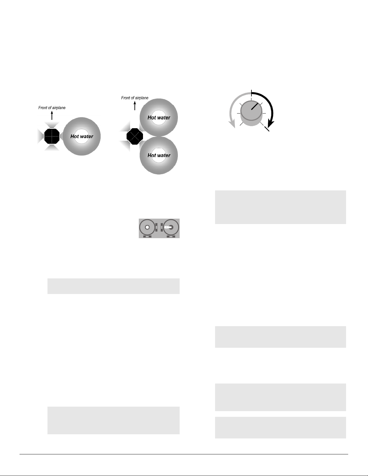
4.Assign the pitch channel:
a. If the Roll/Pitch Sensor has one win-
dow facing forward (as shown be-
low, left), fill a plastic soda bottle
with hot water (at least 120°F or
49°C) and cap the bottle.
or
If the Roll/Pitch Sensor has two windows facing forward
(as shown below, right), fill two plastic soda bottles with
hot water (at least 120°F or 49°C) and cap the bottles.
Tape the bottles together.
Tip: You can also use a coffee cup or similar con-
tainer instead of a soda bottle. If you can close the
container, you’ll be less likely to spill the hot water.
Do not use shiny metal cans.
b. Place the bottle(s) in front of the Roll/Pitch Sensor (as
shown below). The servo connected to channel 2 to will
“tick” one or two times (then repeat) to tell you how many
sensors detect the hot water.
Hot water location for
1 forward-facing sensor
window. Channel 2
servo “ticks” one time
(and repeats)
Hot water location for
2 forward-facing sensor
windows. Channel 2
servo “ticks” two times
(and repeats)
FS8CP
FMA
DirectREC CAL
IMPORTANT: Verify operation as described above:
nIf the sensor has one window facing forward, the
servo must tick only once.
nIf the sensor has two windows facing forward, the
servo must tick twice.
If this is not the case, flight stabilization setup
will be incorrect.
c. Slowly move the elevator (pitch) stick
toward you for up elevator (pitch up).
Make the motion last at least 2 seconds
so FS8 Co-Pilot™ can exactly copy
transmitter mixing (if any). FS8 Co-Pilot™ now knows
which channel controls pitch, and how it should respond
when the aircraft is pitching away from horizontal.
continued
continued
FS8 Co-Pilot™ user guide 14 FMA Direct
d. Remove the bottle(s) of hot water.
5.Assign the roll channel:
a. Press the CAL Button 1 time. The LED blinks 2 times (and
repeats slowly), indicating FS8 Co-Pilot™ is in Setup
Mode 2.
b. Place the bottle(s) of hot water to the right side of the right-
facing one or two sensors (as shown below). The servo
connected to channel 2 will cycle one or two times (then re-
peat) to tell you how many sensors detect the hot water.
7.Verify flight stabilization operation:
a. Turn off FS8 Co-Pilot™. (Turning off FS8 Co-Pilot™ ter-
minates Flight Stabilization Setup Mode.)
b. Turn on FS8 Co-Pilot™ without holding any buttons. FS8
Co-Pilot™ is now in Normal Flight Mode.
c. If you assigned a channel for remote on/off, make sure the
transmitter knob, slider or switch is in the on/max position.
Minimum
throw
Maximum
throw
Flight
stabilization
off
Flight
stabilization
on
d. Place the bottle(s) of hot water in front of the forward-fac-
ing one or two sensors to simulate the aircraft pitching
down. Flight stabilization should respond by making the
aircraft pitch up, like this:
nConventional airplane: elevator moves up.
nFlying wing: both elevons move up.
nHelicopter: swashplate tilts back, and does not tilt left
or right.
Note: If the aircraft doesn’t respond at all:
nFlight stabilization may be off. Try moving the
control assigned to remote on/off.
nIf the Pitch/Roll Sensor is unplugged, or if setup
is incorrect, flight stabilization is disabled.
e. Place the bottle(s) of hot water to the right of the right-fac-
ing one or two sensors to simulate the aircraft rolling to the
right. Flight stabilization should respond by making the
aircraft roll left, like this:
nConventional airplane: left aileron moves up, and right
aileron moves down.
nFlying wing: left elevon moves up, and right elevon
moves down.
nHelicopter (boom parallel to ground): swashplate tilts
left, and does not tilt forward or back.
8. Turn off FS8 Co-Pilot™.
9. Check Vertical (“Z”) Sensor operation (if sensor is installed):
a. Reconnect Vertical Sensor cable. Turn on FS8 Co-Pilot™.
Note: If the Vertical Sensor is disconnected while
power is on, flight stabilization is disabled (FS8 Co-
Pilot™ assumes the sensor is defective).
b. Place the bottle(s) of hot water above the Vertical Sensor
to simulate inverted flight. Pitch stabilization should be re-
duced when heat is above the Vertical Sensor. Roll stabili-
zation is not affected. Turn off FS8 Co-Pilot™.
CAUTION: Be certain you get the responses de-
scribed in steps 7d, 7e and 9b. If you do not get
these responses, or if pitch and roll stabilization seem
to affect each other, repeat flight stabilization setup.
Note: Repeat flight stabilization setup if you
reconfigure the aircraft, reprogram your transmitter
or move FS8 Co-Pilot™ to another aircraft.
Go to “Set Auto Trim.” Æ
Hot water location for
1 forward-facing sensor
window. Channel 2
servo “ticks” one time
(and repeats)
Hot water location for
2 forward-facing sensor
windows. Channel 2
servo “ticks” two times
(and repeats)
c. Slowly move the aileron (roll) stick to
the left for left roll. Make the motion last
at least 2 seconds so FS8 Co-Pilot™ can
exactly copy transmitter mixing (if any).
FS8 Co-Pilot™ now knows which channel controls roll,
and how it should respond when the aircraft is rolling to the
right.
6. Assign the remote on/off channel:
Note: Assigning a remote on/off channel is op-
tional, but recommended.
a. Press the CAL Button 1 time. The LED blinks 3 times (and
repeats slowly), indicating FS8 Co-Pilot™ is in Setup Mode 3.
b. Move the knob, slider or switch you want to use to control
remote on/off. Make the motion last at least 2 seconds.
FS8 Co-Pilot™ now knows which channel controls on/off.
To erase the remote on/off channel assignment (which sets
flight stabilization on all the time): Move the previously
assigned pitch or roll stick. (FS8 Co-Pilot™ never assigns
remote on/off to a pitch or roll stick.)
c. In Flight Stabilization Setup Mode 3, remote on/off oper-
ates proportionally. Adjust servo throws on the transmitter
to assure remote on/off functions: moving the transmitter
control from one extreme to the other should turn flight sta-
bilization full on and full off.
To erase all flight stabilization settings: Press and
hold the CAL Button for 10 seconds. This removes
pitch, roll and remote on/off channels learned by
FS8 Co-Pilot™.
continued

FMA Direct 15 FS8 Co-Pilot™ user guide
Set Auto Trim
Auto Trim maintains trim settings when you switch FS8 Co-Pi-
lot™ on and off. These guidelines will help you decide whether
to use Auto Trim:
nBest for beginners: Auto Trim should be on. Take off with
FS8 Co-Pilot™ on, and trim in the air with FS8 Co-Pilot™
on. With Auto Trim on, aircraft stays in trim when FS8 Co-
Pilot™ is turned off in the air.
nBest for experts: Auto Trim should be off. Take off with FS8
Co-Pilot™ off, and trim in the air with FS8 Co-Pilot™ off
(since Auto Trim is off, it has no effect on trim). After turning
on FS8 Co-Pilot™ for emergency recovery, don’t trim, or you
must retrim when FS8 Co-Pilot™ is off.
1. Turn on your transmitter, then turn on FS8 Co-Pilot™ (so FS8
Co-Pilot™ is in Normal Flight Mode).
2. Determine whether Auto Trim is on or off:
a. Turn off flight stabilization using the transmitter’s remote
on/off control.
b. Place a bottle(s) of hot water in front of the right-facing 1
or 2 windows of the Pitch/Roll Sensor.
c. Watch the aircraft’s roll surfaces (ailerons, elevons or
swashplate) as you turn off flight stabilization with your
transmitter.
nIf the roll surfaces move slightly, Auto Trim is on.
nIf the roll surfaces don’t move, Auto Trim is off.
Note: If the Vertical (“Z”) Sensor is installed and
you are setting up indoors, the Auto Trim setting
probably won’t change the pitch surfaces. When in-
doors, the Vertical Sensor usually sees warmer air
above the aircraft (warm air rises to the ceiling), and
FS8 Co-Pilot™ assumes the aircraft is inverted.
3. Change Auto Trim as needed (in Normal Flight Mode, not in
Setup Mode):
nTo turn Auto Trim on (if it is off):
Press the REC Button 6 times.
nTo turn Auto Trim off (if it is on):
Press the REC Button 6 times.
FS8 Co-Pilot™ is now set up.
Go to “Understanding infrared field calibration.” Æ
FS8CP
FMA
DirectREC CAL
Understanding infrared field calibration
This background information will help you understand why
you need to carry out the infrared field calibration (de-
scribed on the next page).
FS8 Co-Pilot’s Pitch/Roll Sensor sees for many miles in all
directions when the model is airborne. Its field of view will
include grass, trees, buildings, pavement, people, cars,
clouds, water and many other objects with different infrared
emissions. The Sensor detects an average infrared tem-
perature sufficient for FS8 Co-Pilot™ to carry out flight sta-
bilization under nearly all conditions.
During calibration, FS8 Co-Pilot’s Pitch/Roll Sensor sees in-
frared temperatures in the immediate vicinity of the model.
This means that you should calibrate over an area repre-
sentative of the general infrared environment—such as
grass—the Sensor will see when the model is airborne.
Once calibrated, large variations in terrain or weather can
affect FS8 Co-Pilot’s ability to stabilize the aircraft. If these
occur, you may need to recalibrate.
The calibration procedure recommends that you not cali-
brate, for example, over asphalt (such as a taxiway, runway
or parking lot). If you were to calibrate over asphalt, the
Sensor would detect the infrared generated by the as-
phalt—not the average for the larger area in which the
model will be flying—resulting in a falsely high temperature
difference.
FS8 Co-Pilot™ conveniently tells you about the infrared
temperature difference it measures on a relative scale of
one (small difference) to ten (large difference). In several
years of testing flight stabilization technology, we’ve made
some important observations:
nFS8 Co-Pilot™ rarely measures a difference of 10.
nFS8 Co-Pilot™ even more rarely measures a difference
of 1.
nReadings of 1 have only been seen over snow, in fog and
when the cloud cover is below two hundred feet. Not
many people will fly in those conditions.
What happens if you use FS8 Co-Pilot™ under the worst
possible conditions? When FS8 Co-Pilot™ doesn’t see a
significant difference in infrared temperature, it doesn’t is-
sue any compensating signals to the receiver. If the model
is trimmed for stable flight, it simply responds to your
commands as though FS8 Co-Pilot™ weren’t in the system.
We recommend that you deactivate FS8 Co-Pilot™ (turn
the Pitch and Roll Throw controls fully counterclockwise) if it
produces a reading of 1 during calibration. Otherwise, you
may experience unexpected flight excursions.
What happens if you calibrate over land and fly over water?
If you fly near a small lake, the Pitch/Roll Sensor doesn’t
see much of a change. If you fly over a larger body of wa-
ter, the Sensor sees a somewhat lower average infrared
temperature compared to flying over land. All you need to
do in this situation is make sure FS8 Co-Pilot™ measures a
moderate to high temperature difference (4 or higher) over
land. FS8 Co-Pilot™ sees a 1 unit drop for each 6º of lower
temperature difference. For example, if the aircraft is flying
over water that is 12º lower than the land where FS8 Co-Pi-
lot™ was calibrated, FS8 Co-Pilot™ has 2 units less tem-
perature difference to work with. If the original calibration
number was 5, then the effective calibration number would
be 3 over water. However, if FS8 Co-Pilot sees a 2 over
land, it would see 0 over water. It is safer to fly over large
lakes when the temperature difference is 4 or higher over
land.
Go to “At the field.” Æ

FS8 Co-Pilot™ user guide 16 FMA Direct
At the field
When using FS8 Co-Pilot™, you’ll need to add two routines to
your normal preflight checks:
nInfrared field calibration — before your first flight of the
day, and any time there is a significant change in the weather.
nFS8 Co-Pilot™ preflight check — before each flight, as part
of your regular preflight check.
Infrared field calibration
IMPORTANT:
nCalibrate before your first flight of the day, and
any time the weather changes significantly.
nCalibrate outside, near the area where you will
be flying.
nCalibrate before every flight at night.
Infrared field calibration precautions
Flight stabilization derives precision and flexibility from the
calibration procedure. Please read and observe the following
guidelines for the best, safest operation with the greatest margin:
nAs nearly as possible, calibrate flight stabilization over the
type of terrain the aircraft will be flying over. For example,
do not calibrate over bare dirt if the aircraft will be flying
over light vegetation.
nGrass provides the best, most consistent reference terrain, but
snow is the coolest reference terrain.
nIf the flying area has variable terrain, calibrate over the
coolest part. This provides a conservative, lower calibration
number, and assures a greater margin over warmer reference
terrain. Typical infrared temperatures, in order from coolest
to warmest are: snow, water, grass, light vegetation, sand, and
asphalt or concrete.
nIf you calibrate over an artificially warm medium such as as-
phalt or concrete, the infrared temperature over anything else
will be lower, which reduces the temperature difference (be-
tween earth and sky) available for flight stabilization to work
with. If at all possible, don’t calibrate over asphalt or con-
crete.
nIf the aircraft will be flying over patchy snow, calibrate over
the snow.
nA calibration reading of 1 is rare. Do not fly using flight sta-
bilization when a reading of 1 is obtained over the coolest ter-
rain present. Instructions for disabling flight stabilization
are provided on page 21.
nHelicopters require extra precision to hover. For that reason,
you should only use flight stabilization on a helicopter when
the calibration reading is 3 or greater.
About infrared field calibration
The infrared field calibration enables FS8 Co-Pilot™ to measure
the environment in which it will be flying. The calibration has
two parts:
1. FS8 Co-Pilot™ determines the infrared temperature dif-
ference between sky and ground.
When this step is complete, FS8 Co-Pilot™ tells you the in-
frared temperature difference by cycling the servos. FS8 Co-
Pilot™ works well with moderate to high temperature differ-
ences, but is less effective with a very small temperature dif-
ference. By counting the servo cycles, you can decide
whether conditions are favorable for flying with FS8 Co-Pi-
lot™.
This step also enables FS8 Co-Pilot™ to determine when full
pitch correction is needed. For example, when the aircraft is
heading directly for the ground, Co-Pilot™ will apply maxi-
mum pitch correction.
2. FS8 Co-Pilot™ determines how the infrared horizon ap-
pears when the aircraft is level. This enables it to compen-
sate for minor Pitch/Roll Sensor tilt (for example, caused by
dihedral when the Sensor is mounted on a wing). FS8 Co-Pi-
lot™ sets its own trims for level flight.
Infrared field calibration procedure
CAUTION: If you are near a flying field, observe
frequency control rules and comply with local proce-
dures before turning on your transmitter. If your
transmitter is on—even for a few seconds—it will in-
terfere with a radio system already operating on the
same frequency.
1. Measure the temperature difference between earth and sky.
a. Take the model to a spot (grass is best) representative of
the area where you will be flying. The aircraft should be at
least 100 feet (30 meters) from anything that radiates heat
(heat from buildings or parking lots can affect calibration).
b. Turn on the transmitter, then turn on FS8 Co-Pilot™. Do
not press the CAL Button yet.
c. If you are using the Vertical Sensor, set the plane level on
the ground, then go to step 1.d.
or
If you are not using the Vertical Sensor: point one of the
Pitch/Roll Sensor windows straight down at the ground
(and the opposite window straight up at the sky), as shown
in the next column.
continued

FMA Direct 17 FS8 Co-Pilot™ user guide
Fixed wing aircraft
Helicopter
d. Press and hold the CAL Button for 2 seconds. The servos
cycle once to indicate infrared calibration has begun (a
cycle is one complete back and forth servo motion).
e. Release the CAL Button, then count servo cycles. Here’s
what the count indicates:
n3 to 10 cycles: FS8 Co-Pilot™ will provide stabiliza-
tion.
n2 cycles: FS8 Co-Pilot™ will provide some stabiliza-
tion, but will be more sensitive to terrain hot spots.
n1 cycle: Do not fly using FS8 Co-Pilot™: turn it off us-
ing any of the following methods:
lTurn off FS8 Co-Pilot™ using the knob or slider on
your transmitter (if you assigned remote on/off to a
channel during flight stabilization setup); turn off
Auto Trim, and/or
lDisconnect the Pitch/Roll Sensor from FS8 Co-Pi-
lot™, and/or
lRotate both Throw potentiometers fully counterclock-
wise.
2. Set level orientation.
After step 1, the servos will cycle slowly. During this period:
a. Place the model level on the ground as shown in the next
column. It’s important to make the aircraft absolutely
level, so take your time. If the model has conventional
(taildragger) gear, support the tail with an object so the air-
plane is in a level attitude.
Airplane with tricycle gear level on grass
Prop tail of taildragger so fuselage is level
Helicopter level on grass. A bubble level (arrow) will
enable you to position the helicopter accurately
b. After the model is level, walk at least 10 feet (3 meters)
away, then move any stick. The servos will cycle once, in-
dicating that level orientation is set.
Go to “Preflight check.” Æ
continued

FS8 Co-Pilot™ user guide 18 FMA Direct
b. Point the model’s nose straight down, and assure the air-
craft responds like this:
nConventional airplane: elevator moves up.
nFlying wing: both elevons move up.
nHelicopter: swashplate tilts back, and does not tilt left
or right.
Note: Disconnected or broken sensor cables will
disable flight stabilization. If flight stabilization does
not appear to be working, make certain the sensor
cables are plugged in at both ends. If a cable is not
broken, flight stabilization will return when it is prop-
erly connected between the sensor and FS8 Co-Pi-
lot™.
c. Turn flight stabilization off (if it can be controlled from the
transmitter) or set the Pitch Throw pot to minimum. This
should significantly reduce the aircraft’s pitch throw (eleva-
tor, elevons or swashplate).
d. Turn flight stabilization on or set the Pitch Throw pot to the
desired level.
6. Check roll compensation:
a. Turn flight stabilization on (if it can be controlled from the
transmitter) or set the Roll Throw pot to maximum. Set
dual or tri rates to high.
Note: In step 6b, if you can’t conveniently move the
aircraft, place your hand or a hot object to the right
of the right-facing one or two windows on the Pitch/
Roll Sensor.
b. Hold the aircraft’s body level, roll it to the right, and assure
the aircraft responds like this:
nConventional airplane: left aileron moves up, and right
aileron moves down.
nFlying wing: left elevon moves up, and right elevon
moves down.
nHelicopter (boom parallel to ground): swashplate tilts
left, and does not tilt forward or back.
c. Turn flight stabilization off (if it can be controlled from the
transmitter) or reduce Roll Throw pot to minimum. This
should significantly reduce the aircraft’s roll throw (aile-
rons, elevons or swashplate).
d. Turn flight stabilization on or set the Roll Throw pot to the
desired level.
7. Check pitch and roll neutral positions:
a. Place the aircraft level on the ground.
b. With flight stabilization on, the pitch and roll surfaces
should be centered (or helicopter swashplate level).
8. Check that dual or tri rates are set to high.
High rates are required to override flight stabilization.
9. Make sure Pitch/Roll Sensor and Vertical Sensor windows are
clean.
If necessary, clean windows with alcohol and cotton-tipped
applicator.
10. Check failsafe operation: Turn off the transmitter. Servos
with failsafe presets should move to those positions. Turn
on the transmitter! (The receiver will count this as one
failsafe).
FS8 Co-Pilot™ preflight check
IMPORTANT:
nPerform the preflight check outside, and after the
infrared calibration is complete.
nAdd this routine to your other preflight checks.
1. Check for interference:
a. With your transmitter off, turn on FS8 Co-Pilot™.
b. Watch the LED:
nLED on for 2 seconds, then off (and stays off) = no inter-
ference. Go to step 2.
nContinuous blinks = interference is present. Find and
eliminate the interference before continuing.
Tip: Leave FS8 Co-Pilot™ on continuously (with
your transmitter off) to check for intermittent inter-
ference.
2. Turn on your transmitter. Receiver LED will blink.
3. Check receiver battery voltage:
a. While moving all transmitter
sticks (to load radio system),
press REC Button 1 time.
b. Count LED blinks:
nEach long blink = 1 volt.
nEach short blink = 0.1 volt.
(Example: 4 long blinks + 9
short blinks = 4.9 volts.)
4. Check radio system range:
Range checking FS8 Co-Pilot™ is easier than other receivers.
A failsafe condition will occur at the limit of the range. FS8
Co-Pilot’s LED shows whether a failsafe occurred during the
range check. Just check the LED after you return to the
model.
Note: The usual way of finding the range limit by
looking for servo glitches does not work with FS8
Co-Pilot™. Since FS8 Co-Pilot™ reconstructs
noisy or missed frames, servo glitches are much
less noticeable.
a. Collapse transmitter antenna.
b. Walk 50 paces (about 150 feet or 45m) away from model.
c. KEEP TRANSMITTER ON and return to model.
d. Watch the LED:
nContinuously on: no failsafes. Go to step 5.
nBlinking: failsafes occurred. Find and correct the range
problem before continuing.
If you have range problems, see “Range checking” on page 22.
5. Check pitch compensation:
a. Turn flight stabilization on (if it can be controlled from the
transmitter) or set the Pitch Throw pot to maximum. Set
dual or tri rates to high.
Note: In step 5b, if you can’t conveniently move the
aircraft, place your hand or a hot object in front of
the forward-facing one or two windows on the Pitch/
Roll Sensor.
continued continued
FS8CP
FMA
DirectREC CAL

FMA Direct 19 FS8 Co-Pilot™ user guide
11. Test all transmitter controls—including flight stabilization re-
mote on/off—for normal operation.
12. If you are flying with a buddy box: Switch on the buddy box
for at least 2 seconds before each flight. (FS8 Co-Pilot™ re-
quires 1 second to detect the buddy box. After that, the tran-
sition is instantaneous. However, you must allow FS8 Co-Pi-
lot™ to identify the buddy box before each flight, on the
ground, before taking off.)
Working with FS8 Co-Pilot™
nSensor check. When you turn on FS8 Co-Pilot™, it checks
to make sure the sensors are connected. If a sensor cable is
disconnected or broken, flight stabilization is automatically
disabled. If flight stabilization doesn’t seem to be working,
check the cables.
Tip: FS8 Co-Pilot™ Viewer Software displays a
cable failure indicator when a cable operates inter-
mittently. To clear the cable failure indicator in the
Viewer, cycle power to FS8 Co-Pilot™.
nControlling flight stabilization depends on how you set up
your transmitter and FS8 Co-Pilot™ for remote on/off:
lIf you assigned remote on/off to a proportional channel, it
works as shown below. Besides remote on/off, you can set
throw based on flight conditions.
Minimum
throw
Maximum
throw
Flight
stabilization
off
Flight
stabilization
on
For example, you can adjust throw to match a student’s
skills while the model is airborne. As the student gains
confidence, decrease throw to provide less stabilization.
lIf you assigned remote on/off to a switched channel, you
can turn flight stabilization on and off during flights. When
flight stabilization is on, throw is set by the two manual
Throw potentiometers on FS8 Co-Pilot™. To adjust throw,
you must land the aircraft and manually change the Throw
pots.
With on/off control, an instructor can take off and trim
without flight stabilization, then turn it on when giving con-
trol to a student. Or, you might use flight stabilization for
most flying, turn it off for aerobatics or inverted flight, then
turn it back on again for landing.
lIf flight stabilization is not assigned to a channel, it is al-
ways on during a flight. Throw is set by the two manual
Throw pots on FS8 Co-Pilot™. To adjust throw, you must
land the aircraft and manually change the Throw pots.
nInverted flight. How flight stabilization responds to inverted
flight depends on whether you are using the optional Vertical
Sensor:
lWith the Vertical Sensor, the aircraft will roll from inverted
back to its normal attitude (because flight stabilization el-
evator response is reduced when the aircraft is inverted).
lWithout the Vertical Sensor, the aircraft may loop from in-
verted back to its normal attitude—if it is high enough!
CAUTION: If the aircraft is too low it will crash!
lTo intentionally fly inverted (including in loops, half loops
and other maneuvers where the aircraft is inverted) or in
knife edge orientation: Turn off flight stabilization.
nOverwhelming interference or loss of signal—every pilot’s
worst nightmare—is where FS8 Co-Pilot™ may save your
plane. When FS8 Co-Pilot™ is set up with servo failsafe po-
sitions and flight stabilization is on (or is activated by a
failsafe setting), the plane moves into a stable, predictable
flight path in the event of interference or signal loss.
lReasons FS8 Co-Pilot™ enters Failsafe Mode:
uYou accidentally turned off your transmitter.
uYour transmitter batteries are depleted.
uSomeone else turned on a transmitter on your channel.
uThere is radio interference from some unknown source.
lHow you’ll know FS8 Co-Pilot™ is operating in Failsafe
Mode: the aircraft won’t respond to your commands.
lWhat you should do:
1. IMMEDIATELY WARN OTHER PILOTS AND
SPECTATORS.
2. Make sure your transmitter on/off switch is on.
3. Hold the antenna vertical and high to increase signal
strength.
4. Check your transmitter’s battery status.
5. Ask other pilots if anyone turned on a transmitter on
your channel. If someone did, tell them to turn off their
transmitter immediately.
6.Attempt to regain control of the aircraft.
7. If you are unable to regain control of the aircraft, keep it
in sight and continue warning everyone in the area.
lIf you can’t fix the problem, the aircraft should circle and
descend slowly to the ground (but that’s better than the
plane drilling itself into the ground or flying out of sight).
continued
Tips for trimming
nIt’s best if the aircraft’s trim doesn’t change when you re-
motely switch Co-Pilot™ on or off. Trim shift can occur if
the model is not level when you set level orientation (step
2 in the “Infrared calibration” procedure on page 16). If
you notice trim shift, calibrate again. If that doesn’t
eliminate trim shift, try slightly tilting the aircraft’s position
during calibration to compensate.
nIf the aircraft is flying in a narrow valley, then high terrain
or tall trees on one side will affect the average infrared
radiation on that side. To the extent possible, calibrate
with the model oriented diagonally to the valley and
slightly tilt the aircraft’s axes to compensate.
nHelicopters are very sensitive to small out-of-trim condi-
tions. You may need to adjust Co-Pilot’s trims (see tips
above) to match your flying site. A little effort here will
pay off with added precision.

FS8 Co-Pilot™ user guide 20 FMA Direct
nIf you notice a small difference in trim when turning FS8 Co-
Pilot™ on and off, re-trim with FS8 Co-Pilot™ off. If you
still have trim differences between FS8 Co-Pilot™ on and off,
compensate by raising or lowering the nose a little in the lev-
eling step of the infrared calibration.
nIt’s always a good idea to find out how your airplane handles
at low speed (do this at high altitude). This will help you get
a feel for how the plane will behave during landing. FS8 Co-
Pilot™ makes landing much easier by keeping the plane level
during the approach.
Flying a conventional airplane
nTo take off with tricycle landing gear:
1. Increase throttle to begin roll-out.
2. Keep the plane moving straight with rudder.
3. Pull back on the stick (up elevator) to lift off.
nTo take off with taildragger landing gear (see explanation be-
low):
1. Apply full up elevator when taxiing and at the beginning of
takeoff.
2. Increase throttle to begin roll-out.
3. Keep the plane moving straight with rudder.
4. As the plane gains speed, ease off the elevator, but keep
enough for lift off.
Why tail-draggers handle differently with flight
stabilization
Recall that flight stabilization attempts to keep an
aircraft level. While a tail-dragger’s tail wheel is on
the ground, the airplane isn’t level. Flight stabiliza-
tion tries to level the plane by feeding in down el-
evator. If you don’t counteract this by holding full up
elevator during ground maneuvers, the tail may
come up when it shouldn’t—causing loss of ground
control.
nTo make a turn:
1. Hold aileron in the direction of the turn.
2. Apply a little up elevator to maintain altitude.
3. Center the stick (but don’t let go of the stick!) to return to
level flight.
nTo fly straight and level: Center the stick (but don’t let go of
the stick!). You may need to adjust elevator trim to maintain
level flight. Pitch angle changes with speed, so adjust eleva-
tor trim when you vary the throttle.
nTo recover from errors such as dives and unintended rolls:
Center the aileron/elevator stick (but don’t let go of the
stick!). FS8 Co-Pilot™ takes over and levels the plane.
nIf the engine dies, apply a little down elevator to maintain air-
speed. This is especially important for sport planes.
Flying with FS8 Co-Pilot™
General flying information
Note: This section discusses unique aspects of fly-
ing with FS8 Co-Pilot™. It is not a substitute for
flight instruction from an experienced pilot.
nIf you are a beginner, obtain help from an experienced mod-
eler. FS8 Co-Pilot™ makes it easier to learn to fly, but it can-
not teach you how to fly—only an experienced flyer can do
that.
nFS8 Co-Pilot™ cannot correct for reversed controls, binding
linkages, a balky engine or any other problems. Make certain
your entire radio system is properly installed and working cor-
rectly before flying. Be sure your aircraft is airworthy. If the
airplane hasn’t been flown before, have a qualified pilot check
it out—on the ground and in the air.
nAlways perform an infrared calibration at the field before
each flying session. Recalibrate after significant changes in
the weather, or if you go to another field.
nFlying with FS8 Co-Pilot™ is different from normal flying.
When FS8 Co-Pilot™ is on, it is always attempting to keep
the aircraft level. You’ll need to provide more stick motion to
override this tendency. This is great for beginners, but experi-
enced pilots will want to tailor performance.
nInitial flight tests and throw adjustments should be made by
an experienced pilot.
nIf you can control FS8 Co-Pilot™ with your transmitter, you
can have the best of both worlds: turn FS8 Co-Pilot™ on
when you need it, turn it off when you don’t. Or use FS8 Co-
Pilot™ as a “panic button” to quickly recover the aircraft
from an unusual attitude.
nIf you notice the aircraft shaking or oscillating while it is air-
borne, Co-Pilot’s throw is set too high. Take action as fol-
lows:
lIf you have proportional control of FS8 Co-Pilot™ (versus
on/off control), reduce throw using the knob on your trans-
mitter. If necessary, turn the knob to the full off position
and land the aircraft.
lIf you have on/off control of FS8 Co-Pilot™, switch FS8
Co-Pilot™ off and land.
lIf you don’t have remote control of FS8 Co-Pilot™, land
the aircraft.
After landing, decrease throw by 1/8th turn. Continue
flight testing and reducing throw until the aircraft flies
smoothly.
nIncrease throw on windy days. The aircraft will fly more
smoothly.
nDon’t attempt intentional inverted or knife edge flight until
you gain experience. Without the Vertical Sensor, FS8 Co-Pi-
lot™ reacts to inverted flight by applying full roll and full up
elevator, which can put the plane into a descending loop until
it is upright. Unless the plane is very high, it may crash. For
aerobatic maneuvers, set Throw to the intermediate or expert
level, or turn off flight stabilization.
continued
continued
Table of contents
Other FMA Direct Receiver manuals


