FMA PowerLab 6 User manual

PowerLab 6
User’s Guide
For firmware ver. Starting at 1.05
© 2011, 2013, 2014 FMA,Inc.
Updated: 09/02/2014

2
Contents
Contents............................................................................................................. 2
About PowerLab 6................................................................................................................ 5
Using PowerLab 6 ............................................................................................. 7
Quick reference.................................................................................................................... 7
Set Smart Power Management............................................................................................ 9
Set options ......................................................................................................................... 11
Connect packs: basic........................................................................................................ 12
Connect packs: advanced................................................................................................. 14
Configuration B.................................................................................................................. 15
Configuration C.................................................................................................................. 16
Configuration D.................................................................................................................. 18
Configuration E.................................................................................................................. 20
Configuration F .................................................................................................................. 21
Configuration G.................................................................................................................. 22
Configuration H.................................................................................................................. 24
Power supplies................................................................................................................... 26
Charge/discharge/cycle/monitor a pack .......................................................................... 27
Start faster..................................................................................................................................................... 29
Charge/discharge/cycle packs in parallel........................................................................ 30
Expansion Channel Mode ................................................................................................. 31
Regenerative discharge..................................................................................................... 33
Modify a preset................................................................................................................... 34
Manage presets.................................................................................................................. 35
Clear a User Preset....................................................................................................................................... 35
Copy a Library Preset................................................................................................................................... 35
Using the Charge Control Software............................................................... 37
About the CCS.................................................................................................................... 37
Installing the CCS .............................................................................................................. 38
Cells tab.............................................................................................................................. 39
Operating from the Cells tab........................................................................................................................ 39
Helpful hints .................................................................................................................................................. 40
Internal Resistance tab...................................................................................................... 41
Supply tab........................................................................................................................... 42
DC Power Supply section ............................................................................................................................ 42
Supply Status section .................................................................................................................................. 42
Battery Power Source section..................................................................................................................... 42
Expansion Channel section......................................................................................................................... 43
Firmware tab....................................................................................................................... 44
Full firmware and preset update process................................................................................................... 45
Options tab......................................................................................................................... 46
Visual Settings section................................................................................................................................. 46
Preset Settings section ................................................................................................................................ 46
Audio Settings section................................................................................................................................. 46
Start Settings section................................................................................................................................... 46
Save and load options.................................................................................................................................. 47
Presets tab.......................................................................................................................... 48

3
Edit a User Preset ......................................................................................................................................... 48
Information about properties....................................................................................................................... 48
Save, load, backup and restore User Presets............................................................................................ 49
Advanced properties .................................................................................................................................... 50
Errors tab............................................................................................................................ 51
Errors in custom presets ............................................................................................................................. 51
Graphs ................................................................................................................................ 52
Exporting graph data.................................................................................................................................... 53
Generate a custom fuel table............................................................................................ 54
About fuel tables........................................................................................................................................... 54
Run multiple CCS instances ............................................................................................. 55
Other information............................................................................................ 56
Charging tips...................................................................................................................... 56
General information...................................................................................................................................... 56
Charging packs............................................................................................................................................. 56
Storing packs ................................................................................................................................................ 57
How Auto Current Mode works......................................................................................... 58
Estimating performance factors....................................................................................... 59
FMA Wiring mode vs. XH/EH Wiring mode...................................................................... 60
Switching to XH/EH mode at the PL6: ........................................................................................................ 60
Switching to XH/EH mode using the CCS:................................................................................................. 60
Balance connector wiring ................................................................................................. 61
When using FMA Wiring mode (Factory Default Setting)......................................................................... 61
When using XH/EH Wiring mode................................................................................................................. 65
Open architecture presets................................................................................................. 69
LiPo factory presets........................................................................................................... 70
LiPo Generic Accurate Charge.................................................................................................................... 70
LiPo Generic Faster Charge......................................................................................................................... 70
LiPo Generic High Power............................................................................................................................. 70
LiPo Generic Long Life (4.1V)...................................................................................................................... 70
LiPo Generic Small Balanced...................................................................................................................... 71
LiPo 1s/2s Small Non Balanced .................................................................................................................. 71
LiPo All Brands Storage Charge ................................................................................................................. 71
A123 factory presets.......................................................................................................... 72
A123 2300 mAh Accurate Charge ............................................................................................................... 72
A123 2300 mAh Faster Charge .................................................................................................................... 72
A123 2300 mAh High Power......................................................................................................................... 72
A123 2300 mAh Non Bal. 1-5s...................................................................................................................... 72
A123 2300 mAh Non Bal 8s Fixed ............................................................................................................... 73
A123 1100 mAh Accurate Charge ............................................................................................................... 73
A123 1100 mAh Faster Charge .................................................................................................................... 73
A123 1100 mAh Non Bal. 1-5s...................................................................................................................... 74
A123 1100 mAh Non Bal 8s Fixed ............................................................................................................... 74
A123 All Cpcty Storage Charge................................................................................................................... 74
A123 Store Non Bal. 1-5s ............................................................................................................................. 75
A123 Store Non Bal 8s Fixed....................................................................................................................... 75
NiMH, NiCd and Lead Acid factory presets ..................................................................... 76
NiCd Fast Charge with Trickle..................................................................................................................... 76
NiMH Fast Charge with Trickle.................................................................................................................... 76
NiCd/NiMH 24 Hr Trickle Charge ................................................................................................................. 76
Lead 12V SLA or Gel Cell............................................................................................................................. 76
Specifications: ................................................................................................................... 77
Troubleshooting................................................................................................................. 79

4
Support options ................................................................................................................. 82
REVOLECTRIX limited warranty....................................................................................... 83
Limits and exclusions .................................................................................................................................. 83

5
About PowerLab 6
Simple to operate: just connect PowerLab 6 between a power source and a pack,
select a pack-specific preset and start charging, discharging, cycling or monitoring. No
jumpers, plugs or dials to set! During Auto Charge, PowerLab 6 automatically
determines pack capacity and sets optimal current, then dynamically adjusts charge
rate as needed. Alternatively, select manual charge rates from 10mA to 40A.
Supports both balanced (depending on chemistry) and non-balanced charging (with
certain safety limitations) of the following chemistries:
LiPo (1s to 6s balanced, 1s to 2s unbalanced; maximum charge rate of 2.0A for
unbalanced charging).
Li-Ion (1s to 6s balanced, 1s to 2s unbalanced; maximum charge rate of 2.0A for
unbalanced charging).
A123©/LiFePO4 (1s to 6s balanced, 1s to 8s unbalanced; maximum charge rate
of 20A for unbalanced charging).
LiMn (1s to 6s balanced, 1s to 2s unbalanced; maximum charge rate of 2.0A for
unbalanced charging).
NiCd (1s to 19s; maximum charge rate of 20A).
NiMH (1s to 19s; maximum charge rate of 20A).
6V, 12V, 24V Lead Acid (Flooded, Gel, AGM, SLA).
Holds up to 25 user configurable presets (User Presets), optimized for the different
chemistries, providing charging strategies for most common RC charging needs. Also
holds up to 50 Library Presets. When using the free Charge Control Software, the
number of custom presets is virtually unlimited and will grow over time to meet
industry needs. Replace and customize presets to match your battery inventory.
During balanced charging, each cell is balanced independently, providing exceptional
charging safety and elevating RC packs to the safety level of cell phones. Typical
packs of up to 4Ah capacity charge in 40 minutes or less using charger’s 3C Auto
Current Mode.
Latest technology provides the ultimate in safety—even charges packs having hidden
physical damage without danger of fire. A pack will not charge if individual cell
voltages don’t equal total pack voltage.
Cell balancing to 78μV accuracy with a tolerance of 6mV and automatic over-charge
protection assure longest pack life. Automatic temperature monitoring prevents pack
over-charging at low ambient temperatures and charger damage at high ambient
temperatures. Cold weather settings adjustable per preset.
Selectable modes: charge only, discharge only, cycle (charge/discharge any number
of times) and monitor (no charge or discharge, just measure pack voltage).
Selectable discharge:
Internal discharge 10mA to 8A, 50W max.
Regenerative discharge 10mA to 40A, 1000W maximum when powering the
PowerLab 6 from a Lead Acid battery. Regenerative discharge takes most of that
energy and puts it back into the input battery. For example, when you discharge
a LiPo pack for storage, you will be recharging your Lead Acid input battery.
Multifunction backlit display lets you select presets, replace default presets from a
library and shows charging data such as individual cell voltages, charge current,
supply voltage, and amount of charge (mAh) put into pack. Plus, the unique Fuel
display shows percent capacity remaining in a pack.

6
PowerLab 6 Charge Control Software (CCS, a free download) allows you to
customize, save and load presets (including data displays), and view real-time
charging data and graphs. CCS also manages firmware updates to keep PowerLab 6
operating smoothly, and to keep you up-to-date with latest features and
enhancements.
Parallel charging takes advantage of the PowerLab 6’s high power output. After
connecting packs using Safe Parallel Adapters, simply tell PowerLab 6 how many
packs are attached—charge/discharge rates are automatically multiplied by the
number of “P” selected.
Smart Power Management, once configured, prevents damage to your power supply
or storage battery.
Operates from any 12–32V DC power source. Inputs and outputs are protected
against reverse polarity.
Expansion Channel Mode enables multiple PowerLab 6 units to be inter-connected,
for highly efficient charging of multiple packs of the same chemistry. The primary
PowerLab 6 communicates with the enhancement units, sends selected preset
configurations over the network, and controls all aspects of charging and balancing for
the expansion units.

7
Using PowerLab 6
Quick reference
This quick reference lists common PowerLab 6 tasks. What do you want to do?
To do this…
Do this…
Select power
source type*
1. Apply power.
2. Press any button.
3. At the Power Source? screen, use the INC or DEC button to select Battery
or DC Power Supply (i.e., what is currently powering the PowerLab 6).
4. Press ENTER to display User Preset menu.
Navigate the
menus
In the User Presets menu: Press INC and DEC to scroll through User
Presets. Press and hold INC or DEC to scroll rapidly.
In the User Presets menu: Press ENTER to set up to charge with the
displayed preset.
In menus: Press INC and DEC to scroll through options. Press and hold INC
or DEC to scroll rapidly.
In menus: Press ENTER to select the displayed option and move to the next
screen.
Press BACK to go back one screen.
Press and hold BACK to go directly to the User Presets menu from any
location.
Press INC+DEC (i.e., simultaneously) to access Preset Settings, Charger
Options, Manage Presets and Button Help functions.
Connect a pack
For balanced charging at any current: Attach pack discharge wires to Output
jacks using banana cable, attach 9-pin connector to Balance Port (may
require adapter).
Details
For non-balanced charging: Attach pack discharge wires to Output jacks
using banana cable.
IMPORTANT: To prevent damage to the power source, you must specify the
power source’s voltage and current cutoffs before charging for the first time
with a DC power supply, and before charging for the first time from a battery.
After that, update the power source’s operating characteristics any time you
change to a different DC power supply or battery. You can also specify cutoffs
in the CCS Supply tab.

8
Charge,
discharge, cycle
or monitor a
pack
1. Apply power and select power source (see above).
Details
2. Connect pack.
3. Press INC or DEC to select desired User Preset, then press ENTER.
4. For each question, press INC or DEC to select correct answer, then press
ENTER.
5. CHECKING PACK indicates PowerLab 6 is attempting to detect attached
pack.
6. Screen displays preset’s chemistry. If this matches pack’s chemistry, press
ENTER to start. (If they don’t match, just wait for the next prompt, then press
ENTER to return to the User Preset menu.)
7. During the operation:
Press INC or DEC to view data.
Press ENTER to change charge current.
Press and hold ENTER to stop the operation.
8. “Beep beep beep” indicates the operation is complete. Display shows
elapsed time. Press INC/DEC to review data. Operation is complete, but
“session” remains open so you can review collected data. Press and hold
ENTER to terminate session (this erases session data).
9. Disconnect pack.
10.Press ENTER to return to User Preset menu.
Charge packs in
parallel
To ensure safety, only use REVOLECTRIX Safe Parallel Adapters and stackable
safety banana plugs when charging/discharging/cycling packs in parallel.
Connect up to 9 batteries of same chemistry, cell count and capacity in parallel
by stacking banana plugs. Charge as above, but enter number of packs at
Parallel Packs? question (e.g., 2P, 3P, 4P). PowerLab 6 multiplies preset’s
current setting by the number of “P” selected.
Details
*Assumes Choose Power Source at Startup is enabled in the CCS.

9
Set Smart Power Management
You can set a variety of operating options, including the very important power source
voltage and current limits. You can set Smart Power Management either at the
PowerLab 6 (described below) or in the CCS Supply tab (which is easier).
Because the PowerLab 6 is capable of high power output, it is strongly recommended
that you configure Smart Power Management before you use the PowerLab 6 for
the first time, and set it again any time you significantly change the power source -
either DC power supply or Lead Acid battery.
The PowerLab 6 stores two Smart Power Management profiles: one for a DC power
supply and one for a Lead Acid battery. When you apply power to the PowerLab 6, the
first thing you do is select the profile that matches the power source you are using. This
makes it easy to change the Smart Power Management profile from a DC power supply
at home to a Lead Acid battery at the field.
If you don’t configure Smart Power Management to match your power source(s), these
are the default settings:
DC supply power source:
Voltage lower limit: 10V
Current upper limit: 25A
Battery power source:
Voltage lower limit: 11V
Current upper limit: 25A
Regenerative discharge, when enabled (it is disabled by default):
Regenerative voltage upper limit into Lead Acid battery: 14.40V
Regenerative current upper limit into Lead Acid battery: 10A
The following procedure sets Smart Power Management for both a DC power supply and
a Lead Acid battery.
1. Connect PowerLab 6 to a 10–32V DC power supply or Lead Acid battery.
2. Press any button on PowerLab 6’s panel.
3. At the Power Source? screen, use the INC or DEC button to select Battery or DC
Power Supply (i.e., what is currently powering the PowerLab 6).
4. Press ENTER to display the User Preset menu.
5. Press INC+DEC (i.e., press both INC and DEC at the same time) to display the
Options menu (Choose TASK?).
6. Press INC or DEC until you see Charger Options, then press ENTER.
7. The Charger Address? screen should display PRIMARY CHANNEL (unless you are
IMPORTANT: To prevent damage to the power source, you must specify the
power source’s voltage and current cutoffs before charging for the first time
with a DC power supply, and before charging for the first time from a battery.
After that, update the power source’s operating characteristics any time you
change to a different DC power supply or battery.
Note: All of the above parameters can be adjusted directly on the PowerLab
6, except Regenerative Amps and Regenerative Voltage, which must be set
using CCS.

10
running multiple PowerLabs in Expansion Channel mode). If it doesn’t, press INC or
DEC until you see PRIMARY CHANNEL. Press ENTER.
8. At the Power Source? screen, press INC or DEC to select DC Power Supply, then
press ENTER.
9. At the Supply Current Limit? screen, press INC or DEC to specify the current limit
appropriate for your DC power supply, then press ENTER. (Cutoff current should be
slightly less than the power source’s maximum output current capability. To protect
your power supply from damage, PowerLab 6 will never draw more current than you
specify here, but charge current may not reach the preset or manually set value.)
10. At the Low Sply Limit? screen, press INC or DEC to specify the cutoff voltage, then
press ENTER. (Cutoff voltage should be about 50% lower than the power supply’s
nominal output voltage. Example: For a 24V power supply, set the cutoff voltage to
12V. To protect your power supply, charging stops if the power supply’s voltage
drops below the value you set here.)
11. At the Use Regenerative Discharge? screen, press and hold the BACK button, as
this feature does not apply to DC Power Supply setup. You will be returned to the
User Preset menu. You have now successfully set Smart Power Management for
your DC power supply. Next, repeat the process for your Lead Acid battery.
12. Press INC+DEC (i.e., press both INC and DEC at the same time) to display the
Options menu (Choose TASK?).
13. Press INC or DEC until you see Charger Options, then press ENTER.
14. At the Power Source? screen, press INC or DEC to select Battery, then press
ENTER.
15. At the Battery Current Limit? screen, press INC or DEC to specify the current limit
appropriate for your Lead Acid battery, then press ENTER. (Maximum output current
capability of Lead Acid batteries varies widely. Generally, a standard flooded Lead
Acid car battery might deliver 25A continuously and 50A for short periods. An AGM
style might not have any trouble delivering 50A continuously without suffering
substantially shortened life. To protect your battery from damage, PowerLab 6 will
never draw more current than you specify here, but charge current may not reach the
preset or manually set value.)
16. At the Bat. Low Cutoff? screen, press INC or DEC to specify the cutoff voltage, then
press ENTER. (Cutoff voltage should be no lower than 11V for a 12V Lead Acid
battery. Lower cutoff will provide longer PowerLab 6 operating time at the expense of
Lead Acid battery life. If you are using two 12V batteries in series for 24V operation,
PowerLab 6 will automatically double the cutoff voltage you set here. To protect your
power supply, charging stops if the power supply’s voltage drops below the value you
set here.)
17. At the Use Regenerative Discharge? screen, press INC or DEC to enable or
disable this feature, then press ENTER. (Regenerative discharge puts energy back
into a battery power source during pack discharge cycles.)
18. Press and hold the BACK button to return to the User Preset menu.
Smart Power Management setup is now complete. The next time you cycle power to the
PowerLab 6, it will prompt you to select either DC Power Supply or Battery as the power
source, but it will use the settings you entered to manage power from the selected
source.
See also
CCS Supply tab

11
Set options
1. Connect PowerLab 6 to a 10–32V DC power supply or Lead Acid battery.
2. Press any button on PowerLab 6’s panel.
3. At the Power Source? screen, use the INC or DEC button to select Battery or DC
Power Supply (i.e., what is currently powering the PowerLab 6).
4. Press ENTER to display the User Preset menu.
5. Press INC+DEC (i.e., press both INC and DEC at the same time) to display the
Options menu (Choose TASK?).
6. Press INC or DEC until you see Charger Options, then press ENTER.
7. The Charger Address? screen should display PRIMARY CHANNEL (unless you are
running multiple PowerLabs in Expansion Channel mode). If it doesn’t, press INC
until you see PRIMARY CHANNEL. Press ENTER.
8. The next screen is the Power Source? Screen. (See Set Smart Power Management
for instructions on setting the Power Source and Regenerative Discharge options.)
9. Press ENTER until you see the Node Connector? Screen. For more information
about wiring modes, see FMA Wiring mode vs. XH/EH Wiring mode.
10. Press ENTER until you see the Decimal Places for Cells? screen. At the Decimal
Places for Cells? screen, press INC or DEC to select 2or 3, then press ENTER.
(This controls how many decimal places are displayed in cell voltage data screens.)
11. At the Quiet Charging? screen, press INC or DEC to select Yor N, then press
ENTER. (Y = no beeps during charging, N = beeps during charging.)
12. At the Speaker Volume? screen, press INC or DEC to set speaker volume, then
press ENTER. (1 = quietest. While setting volume, speaker beeps at volume shown
on screen.)
13. At the Charge Complete Beeps? screen, press INC or DEC to set the number, then
press ENTER. (This controls how many times PowerLab 6 repeats “beep beep beep”
when charging is complete.)
14. At the Preset Changes Always Save? screen, press INC or DEC to select Yor
N, then press ENTER. (Y= changes made to a User Preset at PowerLab 6 are
always saved to the loaded preset and uploaded to the Charge Control Software.
Setting to N is not recommended, but it provides a way to temporarily override
preset parameters—once you move to another preset, any changes you made
will be lost and the preset will revert to its previous state.) No matter what you
choose for this option, you can always over-ride charge and discharge rate on-
the-fly at the PowerLab 6 after a charge is started by pressing ENTER. This
method never saves the changes to the preset in use.
15. At the Choose TASK? screen:
Press INC or DEC to select another setup function.
Press BACK to display the User Preset menu.
See also
CCS Options tab
Tip: A setting is saved as soon as you change it. Also, you don’t have to go
through the entire sequence below—at any time, you can press and hold the
BACK button to return to the User Preset menu.

12
Connect packs: basic
Connect the pack to PowerLab 6’s Output jacks, Balance Port or both.
The Balance Port accepts a 9-pin Cellpro balance connector, which supports packs up to
6s. If the pack has a different style balance connector, REVOLECTRIX offers a variety
of adapters for most popular connector types and brands (visit the Cellpro Adapters
section in the REVOLECTRIX Web site).
For all balance charge operations, the pack you connect must have both heavy
discharge wires and a balance connector, you must connect both to PowerLab 6 (good
for any charge/discharge current). The PowerLab 6 does not support balance-wire-only
charging.
For non-balanced charge operations, connect the pack to PowerLab 6 like this:
Note: above illustrations may read “PowerLab 8” because for purposes of these
illustrations, both models are identicall.
Note: Best practice is to connect balance connector first, then connect
discharge wires. When the PowerLab 6 is set to XH/EH wiring mode, you still
must connect both the balance connector and the discharge wires.

13
If stock REVOLECTRIX adapters don’t work for your packs, you can make your own
adapters using the CPBP9P-10 Cellpro battery pigtail 10", 9 position, which consists of a
9-pin connector with un-terminated wires. See Balance connector wiring and the “CellPro
Battery Wiring Diagram”available from the REVOLECTRIX Web site.
See also
Balance connector wiring
XH/EH wiring mode
Note: After a charge is initiated, never alter the connections between the
charger and the battery packs. Always end the current charge session before
making any connection changes. See page 28 for more information about
STARTING and STOPPING charge sessions.

14
Connect packs: advanced
The table below lists several common PowerLab 6 charging configurations. Find the con-
figuration that most closely matches how you want to charge, then click the “Details” link
for more information.
Connect
Number of
Number
Discharge
Number of
Ref
packs
of PL6s
Mode
Balance wires
wires
power sources
A
this configuration not available on PowerLab 6
B
1
1
Normal
Yes
Yes
1
Details
C
2 and up*
1
Normal
Yes
Yes
1
Details
D
1 (10s and up
1
Normal
Yes
Yes
1
Details
with center tap)
E
2
2
Normal
Yes
Yes
1
Details
F
2
2
Normal or
Yes
Yes
1
Details
Expansion Chan-
nel
G
1 (10s and up
2
Normal or
Yes
Yes
1
Details
with center tap)
Expansion Chan-
nel
H
1 (10s and up
2
Normal
Yes
Yes
2, isolated
Details
with center tap)
*Above 9 packs in parallel, you are responsible for determining the charge/discharge current for each pack.

15
Configuration B
Summary: basic one-pack charging through balance and discharge wires.
Components:
1 PowerLab 6
1 power source
1 standard adapter or Safe Adapter
1 pack
Optional FUIM3 for computer support
PowerLab 6 mode (Normal or Expansion Channel): Normal.
PowerLab 6 maximum charge power: up to 1000W charge to one pack (6s) using
30VDC/1200W power source.
Note: above illustrations may read “PowerLab 8” because for purposes of these illustrations, both
models are identical.

16
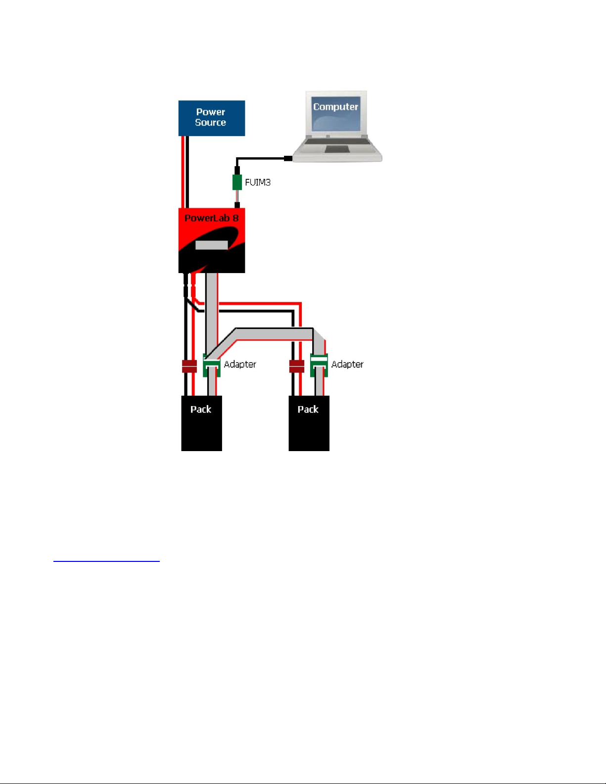
Configuration C
Summary: parallel charging.
Components:
1 PowerLab 6
1 power source
1 Safe Parallel Adapter for each pack (do not use standard adapters)
2 or more packs (above 9 packs in parallel, you are responsible for determining
the charge/discharge current for each pack)
Optional FUIM3 for computer support
PowerLab 6 mode (Normal or Expansion Channel): Normal.
PowerLab 6 maximum charge power: up to 500W charge to each of two packs
charged in parallel using 30VDC/1200W power source.
Constraints:
1 pack per adapter.
Check pack polarity.
Same cell count for all packs.
Use discharge leads.
(Illustration next page)
17
Note: above illustrations may read “PowerLab 8” because for purposes of these illustrations, both
models are identical.
See also
Charge packs in parallel

18
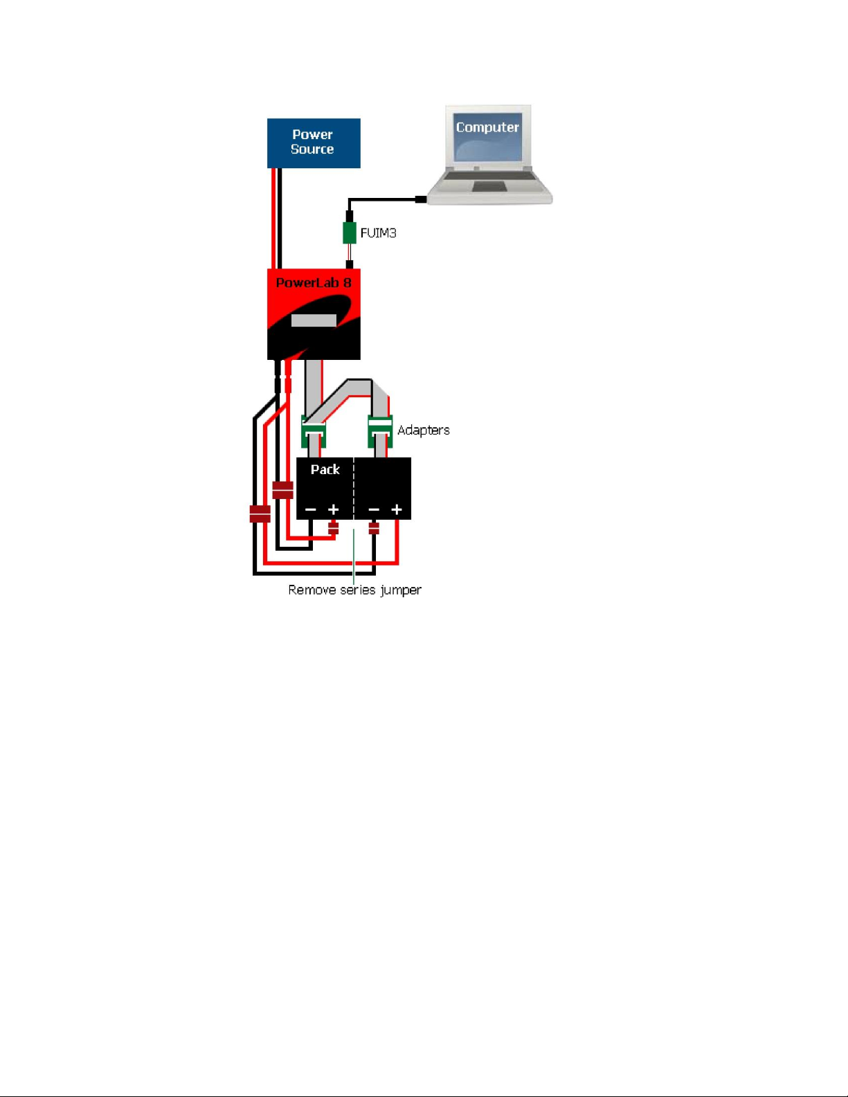
Configuration D
Summary: parallel charging split pack (10s or larger).
Components:
1 PowerLab 6
1 power source
2 Safe Parallel Adapters
1 10s (or larger) split pack with center tap
Optional FUIM3 for computer support
PowerLab 6 mode (Normal or Expansion Channel): Normal.
PowerLab 6 maximum charge power: up to 500W charge to each of two packs
charged in parallel using 30VDC/1200W power source.
Constraints:
1 pack side per adapter.
Check pack polarity.
Same cell count for both sides.
Use discharge leads.
(Illustration next page)
19
Note: above illustrations may read “PowerLab 8” because for purposes of these illustrations, both
models are identical.
20
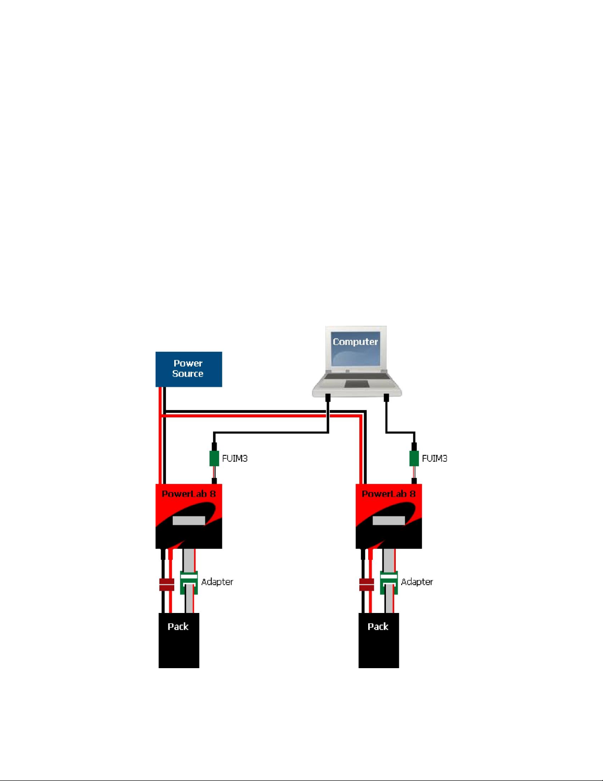
Configuration E
Summary: two PowerLabs charging separate packs, one power source.
Components:
2 PowerLabs
1 power source
2 standard adapters or Safe Parallel Adapters (1 adapter per pack)
2 packs (Safe Parallel Adapters require same cell count for both packs)
2 optional FUIM3s for computer support with 2 CCS instances
PowerLab 6 mode (Normal or Expansion Channel): Normal.
PowerLab 6 maximum charge power: up to 1000W to each pack (6s) using
30VDC/2400W power source. Standard house circuit would likely not provide enough
power; would require 240VAC power supply for full power.
Note: above illustrations may read “PowerLab 8” because for purposes of these illustrations, both
models are identical.
Other FMA Batteries Charger manuals

Popular Batteries Charger manuals by other brands

Xantrex
Xantrex FREEDOM HF 1000 owner's guide

Nordelettronica
Nordelettronica NE286 instruction manual

Circutor
Circutor Wallbox eNext Series installation guide

ULTIMATE SPEED
ULTIMATE SPEED 346098 2004 instructions

GreenWorks Pro
GreenWorks Pro Ultapower 60V CAC801 Operator's manual

Sony
Sony BC-VC10 operating instructions


