Technivolt 1100 User manual

TECHNIVOLT
TECHNIVOLT 1100
1100 SMART
2200 SMART
Charging station for charging
electric vehicles
Installation
instructions

2
Table of contents
Introduction ......................................................... 4
Intended use..................................................................... 4
Symbols used in this manual....................................5
Symbols used on the unit...........................................5
Warning signs in this manual ...................................6
Safety information ............................................. 7
Safety instructions for people with
pacemakers..................................................................... 9
Information about the charging station...... 10
Scope of delivery ............................................................ 10
Operating elements and connections .................. 11
Type plate........................................................................... 12
Identification of the product variants ...................13
Device dimensions .........................................................13
Installation requirements................................. 14
Location selection ..........................................................14
Space requirement for wall mounting............16
Electrical connection .....................................................17
Mains infeed................................................................17
Circuit breaker ............................................................17
Residual current circuit breaker (RCD)............18
Load management ........................................................18
OCPP backend connection.........................................18
Installing the charging station........................ 19
Removing the installation flap.................................. 19
Wall mounting..................................................................20
Electrical installation ......................................... 23
Mains connection............................................................ 24
Network connection...................................................... 25
Completing the installation ............................. 26
Mounting the installation flap...................................26
Mounting the front glass panel................................27
Implementation...............................................................28
Delivery status............................................................28
Final inspection................................................................ 29
LED status indicator........................................... 30
Charge controller................................................ 32
Access to the configuration interface ................... 32
Access via WLAN hotspot.....................................32
Access via Ethernet..................................................33
Alternative .................................................................33
Access via backend..................................................33
Login / Register .........................................................34
Configuration interface ................................................36
Dashboard....................................................................38
Network.........................................................................40
GSM...............................................................................40
LAN ...............................................................................42
WLAN...........................................................................44
WLAN configuration hotspot............................46
NTP ...............................................................................46
Backend ........................................................................47
Connection ................................................................47
OCPP ............................................................................47
Other ............................................................................49
Energy meter............................................................50
Banner gateway......................................................51
Authorisation ..............................................................52
Free charging ...........................................................52
Overview.....................................................................53
RFID seings.............................................................54
RFID whitelist............................................................55
HLC 15118 ...................................................................56
Whitelists......................................................................57
Load management...................................................58
Local .............................................................................58
Modbus .......................................................................58
SMA Sunny Home Manager Interface...........59
EEBUS ..........................................................................60
Dynamic load management..............................61
ASKI via OCPP-S......................................................65
Installation....................................................................66
General installation................................................66
Safety & Security....................................................67
Hardware Usage Meter Seings......................67
System............................................................................68
Overview.....................................................................68
Password....................................................................69
System information ...............................................69

3
2238001000200 - 20220801
System maintenance ............................................69
Firmware update ....................................................69
Factory seings................................................... 70
Shuing down and restarting the charging
station.................................................................. 70
Dismantling the charging station .................. 71
Disposal ................................................................. 71
Technical data...................................................... 72
General ................................................................................72
Input/power connection .............................................72
Output/vehicle connection.........................................72
Fuses..................................................................................... 72
Communication/Protocols.......................................... 73
Network/Ethernet........................................................... 73
Network/WLAN ............................................................... 73
RFID card............................................................................ 73
Mobile communication.................................................73
MID energy meter...........................................................74
Mechanical properties.................................................. 74
Operating conditions ....................................................74
Storage conditions......................................................... 74
Appendix............................................................... 75
CE mark and declaration of conformity...............75
Contact address ..............................................................75
Soware licences............................................................ 75
Service instructions........................................................75
Copyright
The information provided in this document has
been checked with great care. However, no liability
or guarantee can be assumed that all information is
complete, correct and up-to-date at all times. You
can find the current version of the manual in PDF
format in the corresponding product area of the
TechniSat home page..
All contents of this document, in particular texts,
photographs, and graphics, are protected by
copyright. Copying and reproduction of this
document, even in part, requires the wrien approval
of the publisher.
TechniSat is a registered trademark of:
TechniSat Digital GmbH
Julius-Saxler-Str. 3
D-54550 Daun, Germany
TechniVolt is a registered trademark of:
TechniVolt GmbH
Julius-Saxler-Str. 3
D-54550 Daun, Germany
Feedback on this manual
If you have any suggestions for a beer design or
if you are missing information in the instructions,
please send your suggestions to:
techdoc@technivolt.de

4
Introduction
202200801 - 2238001000200
Introduction
This manual describes the mechanical and electrical installation of
the following charging station models:
TECHNIVOLT 1100
TECHNIVOLT 1100 SMART
TECHNIVOLT 2200 SMART
It is intended for a qualified electrician who, on account of his/
her technical training, knowledge and experience, and knowledge
of the applicable standards, can assess and execute the working
steps described in these instructions, and detect any possible
dangers that may be associated them.
These operating instructions are an integral part of the product
and must be kept safely for its entire service life.
Intended use
The TECHNIVOLT charging station is a power supply unit for
electric vehicles, intended for connection to an AC mains supply.
The charging station is designed exclusively for charging electric
vehicles using charging mode 3 (Mode 3 in accordance with the
IEC 61851-1 standard. Connecting other devices is not permied.
The connection to the electric vehicle is established using a
permanently aached type 2 vehicle connector charging cable
according to standard IEC 62196-2.
The TECHNIVOLT charging station is a piece of equipment that
is permanently installed (surface-mounted) and intended for
installation at locations with restricted access (e.g. private
properties, company car parks, depots).
The intended use of this device always includes compliance with
the operating instructions (see "Operating conditions" on Page 74).
Any use of the TECHNIVOLT charging station that is not in
accordance with its intended use is not permied and will result in
the exclusion of warranty, guarantee, and liability.
5
Introduction Introduction
2238001000200 - 20220801
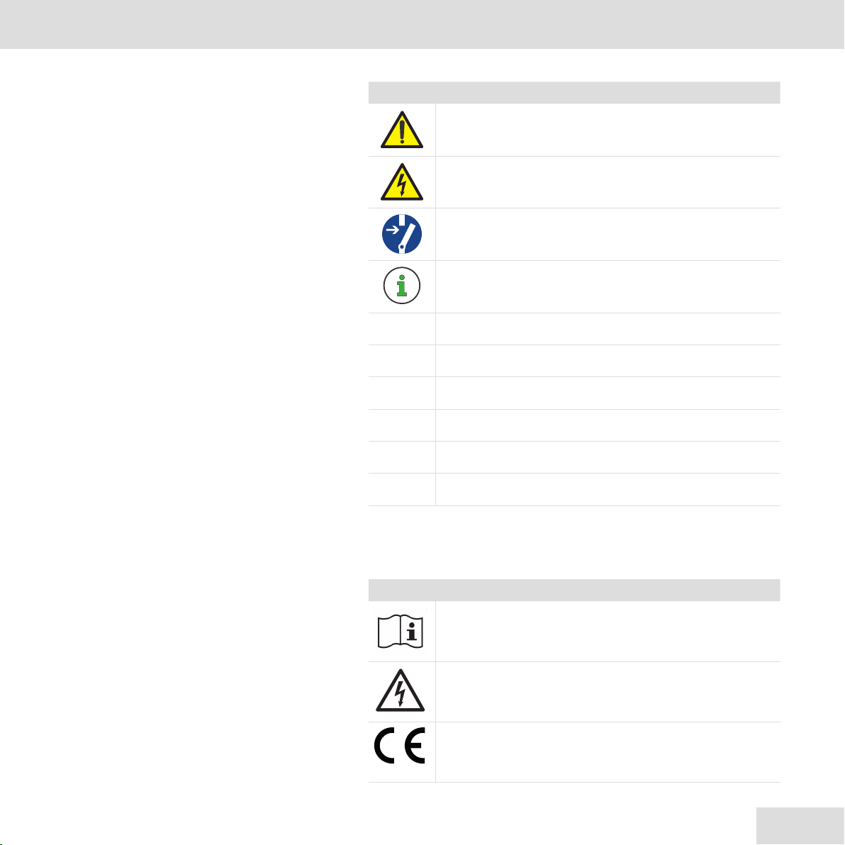
Symbols used in this manual
Symbol Meaning
General warning symbol
Warns about electric danger
Disconnect the power before working.
Indicates tips and recommendations
•Bullet point/List entry
;A condition has been met.
hStep
1, 2, 3...n Steps with a fixed sequence
Result of a step
1Menu only visible if condition is met
Symbols used on the unit
Safety signs are axed to the charging station and must be
complied with.
Symbol Meaning
Read the installation instructions before you open
the charging station or start installation of the
charging station.
A dangerous electrical voltage may be present
inside the charging station aer opening the
housing.
The appliance bears the CE mark - see "CE mark
and declaration of conformity" on Page 75.
6
Introduction
202200801 - 2238001000200
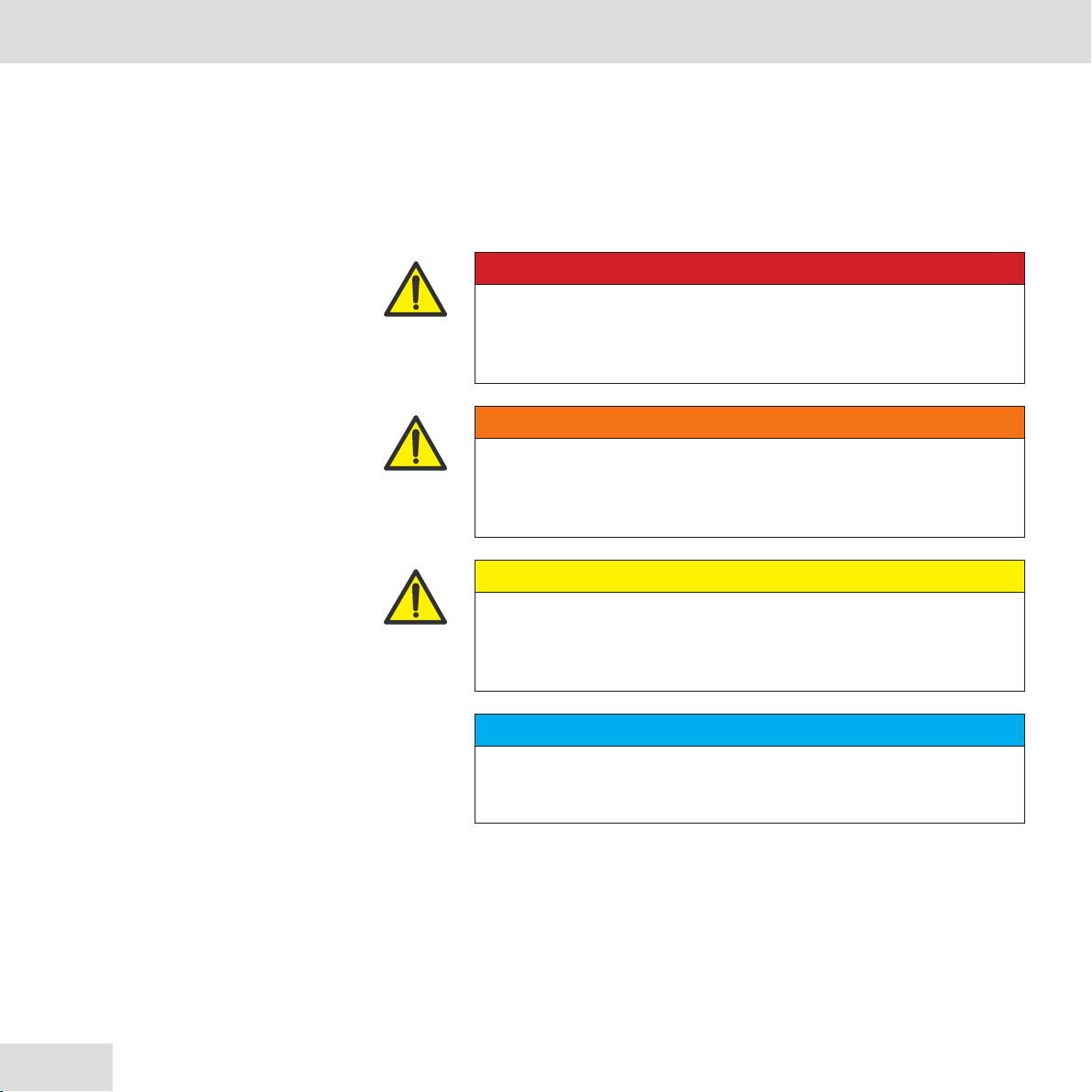
Warning signs in this manual
The following symbols and warning signs are used in this manual
and must be observed.
Warnings prevent life-threatening or fatal injuries.
Observe all notes and follow all instructions.
WARNING
Indicates a dangerous situation that can lead to death or severe
injury if not avoided.
CAUTION
Indicates a hazardous situation with low risk which, if not avoided,
may result in minor or moderate injury or damage to property.
DANGER
Indicates a danger that can lead to death or severe injury if not
avoided.
NOTE
Indicates an important piece of information and/or special feature
relating to specific steps and circumstances.
7
Introduction Safety information
2238001000200 - 20220801
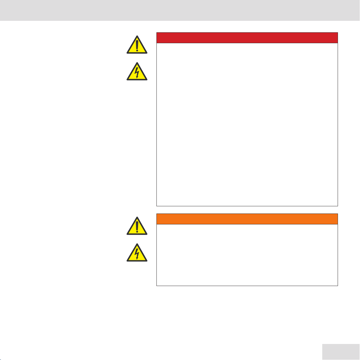
Safety information
For your own protection, please read through the safety instructions
carefully prior to installation.
The manufacturer accepts no liability for damage caused by
inappropriate handling or by failure to comply with the safety
precautions.
DANGER
Danger to life from electrical power.
There is an immediate danger to life by electrocution if you touch
live parts.
All assembly and installation work should be carried out by
an expert electrician. A skilled person is someone who, on
account of their technical training and experience, has adequate
knowledge in the field of the installation to be tested, and who
is acquainted with the applicable governmental safety at work
regulations, accident prevention regulations, guidelines and
the generally-accepted rules of technology (e.g. DIN standards,
VDE stipulations) to an extent whereby they can assess the safe
working status of the installation. Skilled persons can be persons
such as works engineers, master crasmen, technical sta, and
fiers.
The person carrying out the installation must be fit for the work
involved in accordance with DGUV Regulation 103-011 “Working
on live electrical systems and operating material”.
WARNING
Never permit persons (including children) with limited physical,
sensory, or mental capacities, or with a lack of experience and/or
knowledge, to use the electrical equipment unsupervised!
hFailure to observe this warning may result in death or
serious injury.

8
Safety information
202200801 - 2238001000200
These operating instructions must be safely retained for
consultation at a later date.
•The charging station must be connected and approved for
operation in accordance with local rules and regulations.
•For charging stations with power ratings of more than 3.7 kVA and
less than 12 kVA, there is an obligation to notify the grid operator.
•Check the voltage stated on the type plate and only use the
charging station with a suitable power supply voltage.
•Do not continue using the device if you are unsure whether it
is functioning correctly, or if you suspect it may be damaged. In
this case, switch it o! Switch the line and residual current circuit
breaker to OFF. Contact your local distributor.
•The ambient temperature must be between –25 °C and +50 °C,
out of direct sunlight, and the relative humidity must be between
5% and 95%. The charging station must be only used within these
operating conditions.
•The device is intended only for the charging of electric vehicles
that can be charged without ventilation.
•The charging station must only be operated when mounted
vertically.
•The charging station must be mounted on a non-combustible,
smooth surface.
•The charging station must not be installed in enclosed cabinets.
•The charging station must not be installed in areas where there is
a risk of flooding.
•Do not use the charging station in places where explosive or
flammable substances (e.g. gases, liquids, or dust) are stored or
are present.

9
Safety information Safety information
2238001000200 - 20220801
•The device is designed for use both indoors and outdoors. If the
device is to be installed outdoors, all the connection devices for
outdoor operation must be designed and properly installed so as
to ensure that the prescribed IP protection rating is retained.
•The charging station must not be used with a cable extension,
thus avoiding the risk of fire or electric shock.
•Vehicle adapters must not be used to connect a vehicle coupling
to a vehicle connector.
•A damaged charging station must be immediately taken out of
service.
•A damaged charging cable or charging plug must be replaced
immediately by a qualified electrician.
•The charging station may only be repaired by a qualified electrician.
•When repairing the charging station, only system parts approved
by the manufacturer may be used.
•It is forbidden to make any changes to the housing, the charging
cable, or the internal circuitry. In the event of non-compliance, any
claim to liability and warranty shall be void.
•Signs and markings axed by the manufacturer must not be
altered, removed or made unrecognisable.
Safety instructions for people with pacemakers
Electromagnetic fields can influence and interfere with a pacemaker
or an implantable defibrillator (ICD).
We recommend that people fied with a pacemaker or defibrillator
consult their doctor before using this product.
10
Information about the charging station
202200801 - 2238001000200
Information about the charging station
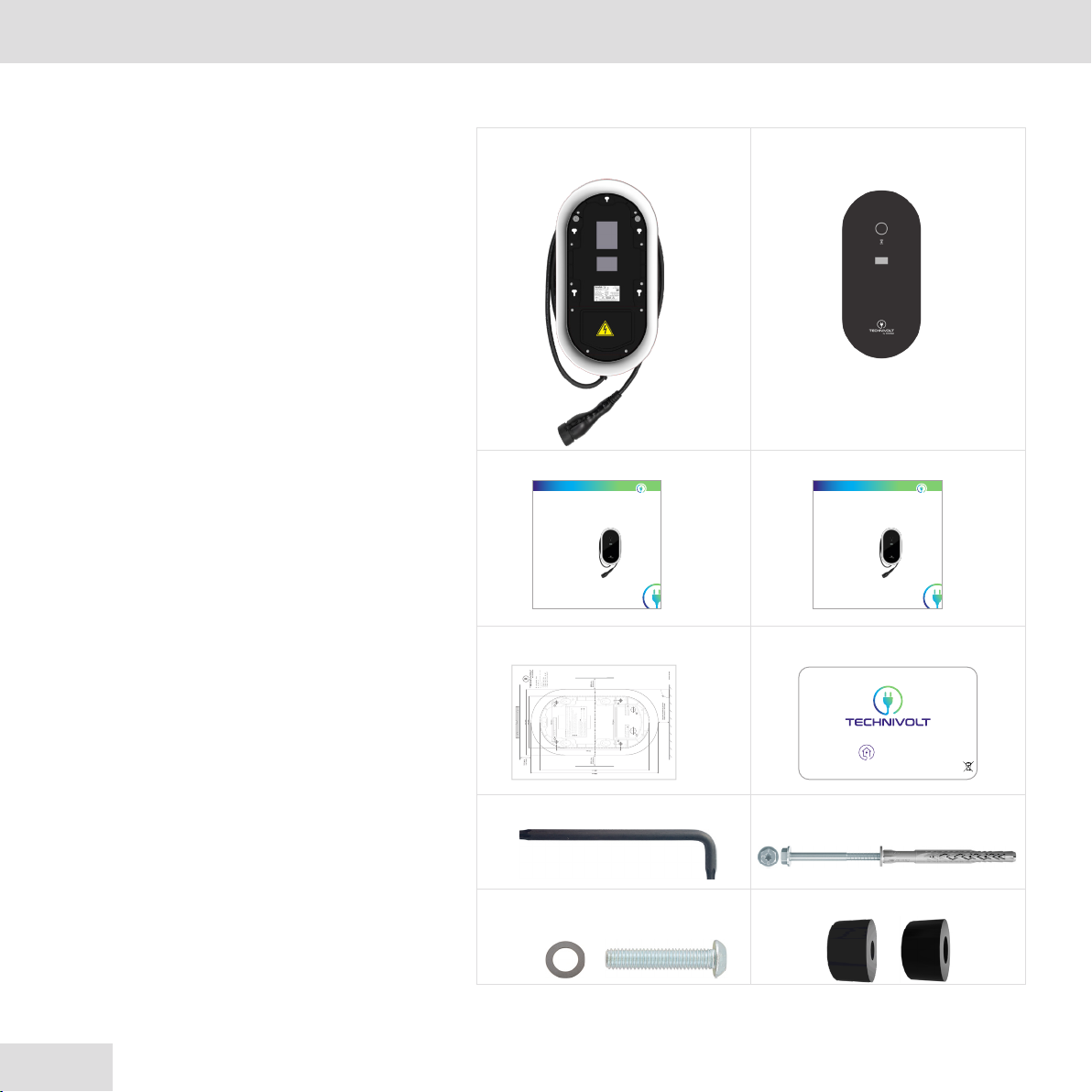
Scope of delivery
1 x TECHNIVOLT charging
station variant
1 x front glass panel
1 set of assembly instructions 1 x instruction manual
1 x drilling template, DIN A1 2 x user RFID cards
1 x angle wrench, Torx-TR 20 Mounting kit
4 x Fischer SXRL 8 x 60 FUS A4
1 x locking screw for glass
panel, Torx-TR 20 M4
2 x M25 gasket, network
TECHNIVOLT
TECHNIVOLT 1100
110 0 SMART
2200 SMART
Ladestation für das Laden
von Elektrofahrzeugen
Montage-
anleitung
TECHNIVOLT
TECHNIVOLT 1100
110 0 SMART
2200 SMART
Ladestation für das Laden
von Elektrofahrzeugen
Bedienungs-
anleitung
Montagehinweis
1. WählenSieeine Montagefläche die eben ist um ein Durchbiegendes Gehäuses
zuvermeiden.
2.Richten Sie die Bohrschablone horizontal aus (Wasserwaage!) und befestigen
Siediese bei Bedarf mit Klebestreifen.
3.Markieren Sie die benötigten Bohrlöcher mit einem Körner oder Bleisti:
4x,Wandbefestigung,Bohrloch Ø 8 mm, Bohrlochtiefe 70 mm.
1x,Netzanschluss,Bohrloch Ø je nach Netzzuleitung.
1x,Ethernetanschluss,Bohrloch Ø je nach Ethernetkabel.
4.Bohren Sie die Löcher wie angegeben.
5.Setzen Sie die 4 Dübel in die Bohrungen A.
6.Befestigen Sie die Ladestation zuerst an den beiden oberen Dübeln Ami t
denSchrauben, Antrieb TX30/SW10.
7. BefestigenSienun die Ladestation nun an den beiden unteren Dübeln Amit
denSchrauben, Antrieb TX30/SW10.
8.Ziehen Sie alle 4 Schraubenüber Kreuz fest.
A
B
C
Bohrschablone
Massstab1:1
DieseBohrschablone ist Teil des
Produktes:
•TECHNIVOLT1100
•TECHNIVOLT1100 SMART
•TECHNIVOLT2200 SMART
4xBohrloch Ø 8 mm, Bohrlochtiefe 70mm
ImLieferumfang:
4xDübel/Schrauben,Fischer SXRL 8 x 60 FUS A4
Bei Unterputzzuführung der
Netzzuleitung in die Lade-
station, markieren Sie Bfür
dieBohrung.
BeiUnterputzzuführung der
Ethernetleitungin die Lade-
station,markieren Sie Cfür
dieBohrung.
Privates Laden
11
Information about the charging station Information about the charging station
2238001000200 - 20220801
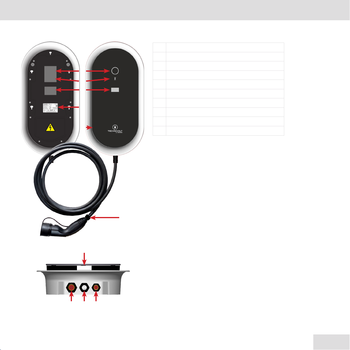
Operating elements and connections
❶Light ring, LED status display
❷RFID reader and brightness sensor
❸MID energy meter (SMART only)
❹Type plate
❺Installation flap
❻Front glass panel
❼Charging cable with charging plug type 2
❽Mains supply input, M32
❾Charging cable input
❿Network/Ethernet input, M25
❶❶
❷❷
❸❸
❼❼
❺❺
❹❹
❻❻
❽❽❾❾❿❿
❹❹
12
Information about the charging station
202200801 - 2238001000200
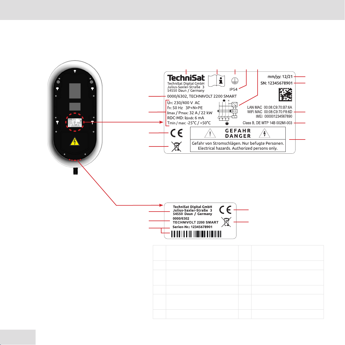
Type plate
The type plate is located on the front of the charging station,
below the front glass panel. The following image shows all the
details on the type plate.
In the final assembled state with the front glass panel, the charging
station can be identified via an additional marking below the front
glass panel.
❶Note to "Read
instructions" ❽MID marking
❷Manufacturer ❾MAC and IMEI
❸Item no. and model
designation ❿Serial number
(bar code)
❹Technical data ⓫Date of manufacture
❺CE marking ⓬RCD-MD switching
symbol
❻Disposal instructions ⓭Protection class
❶❶❷❷
❸❸
❹❹
❺❺
❼❼
❻❻
❽❽
❾❾
❿❿
⓫⓫
⓬⓬⓭⓭⓮⓮
❷❷
❿❿
❸❸
❺❺
❻❻
13
Information about the charging station Information about the charging station
2238001000200 - 20220801
❼Safety advice ⓮IEC protection class
Identification of the product variants
The TECHNIVOLT charging station is available in dierent versions,
which dier electrically and are equipped with dierent functions.
Identify your product using the item no. on the type plate (see
section "Type Plate“ on Page 12).
Variants
TECHNIVOLT
Charging
cable
Length Item no.
Charging
power MID
1100 5 m 0000/6300 11 kW No
7.5 m 0007/6300 11 kW No
1100 SMART 5 m 0000/6301 11 kW Yes
7.5 m 0007/6301 11 kW Yes
2200 SMART 5 m 0000/6302 22 kW Yes
7.5 m 0007/6302 22 kW Yes
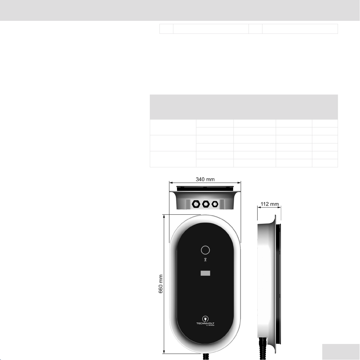
Device dimensions

14
Installation requirements
202200801 - 2238001000200
Installation requirements
Good preparation accounts for half of the installation. Therefore,
you must observe all installation criteria.
•The charging station is suitable for indoor and outdoor installation.
•The location of the charging station at the charging point shall be
designed in such a way that operation of the charging station and
access to the connection point on the electric vehicle are ensured
without any diculty.
•The charging station should ideally be installed on the same side
as the charging socket on the vehicle. The usual parking direction
must also be taken into account.
A light at the charging point is useful. This will make it easier to
charge the electric vehicle at dusk or in the dark.
Location selection
When selecting a location, ensure that the electric vehicle can be
parked at a suitable distance from the charging station and that
the charging cable can be connected without tension.
If possible, mount the charging station in such a way that it is
protected from direct sunlight, to prevent the unit from overheating.
The charging current may be reduced or charging may be
interrupted due to the overheating of the unit.
For outdoor locations, it is recommended that you install a canopy
to protect the charging station from rain.

15
Installation requirements Installation requirements
2238001000200 - 20220801
•The location for the charging station is deemed suitable if:
;there is a sucient power supply available.
;the mounting surface has sucient strength to withstand the
mechanical load.
;the mounting surface is not combustible.
;the mounting surface is flat, so as to avoid bending the enclosure.
;no falling objects can damage the charging station.
;no explosive or flammable substances are stored or are present
on it (e.g. gases, liquids, or dusts).
;no direct water jets can hit the charging station (e.g. garden
hose, high-pressure cleaner).
;it is located away from areas at risk of flooding.
;the charging cable does not have to be routed across trac
routes.
;the positioning of the charging station does not obstruct any
thoroughfares, in particular, if it is possible that wheelchairs
may need to pass, and the charging cable does not obstruct or
impede the passage of wheelchairs.
;the charging cable can be connected to the electric vehicle
without any diculty. The charging cable must not be under
mechanical tension and must rest on the floor.
;it is not located close to playgrounds (playing children!).
16
Installation requirements
202200801 - 2238001000200
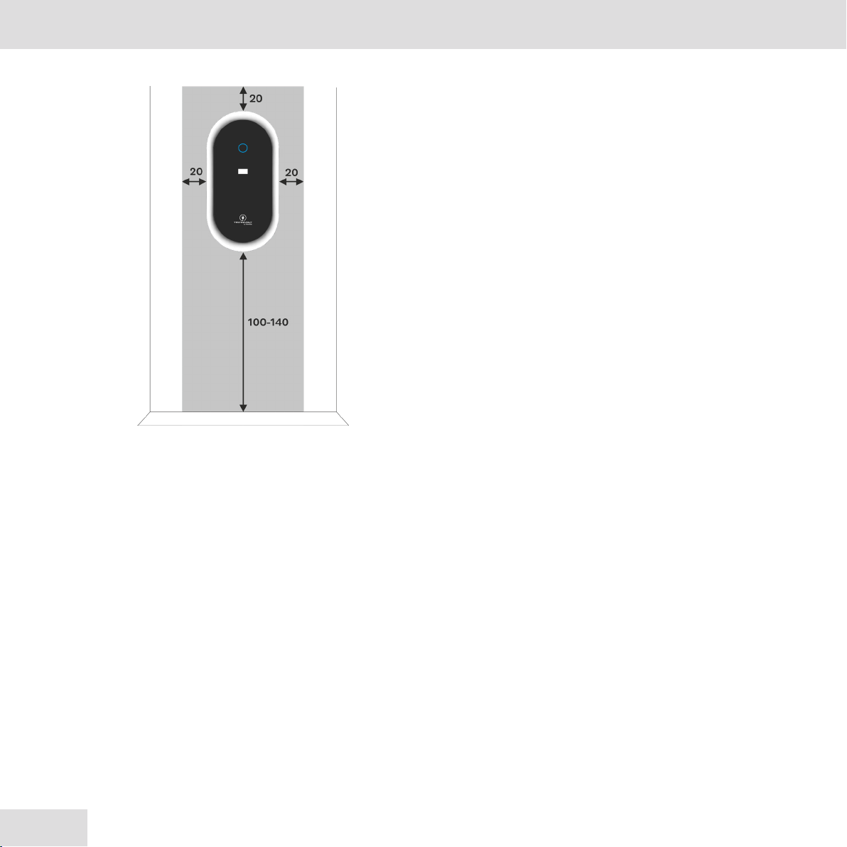
Space requirement for wall mounting
The TECHNIVOLT charging station is surface-mounted.
The space requirement for the TECHNIVOLT charging station is 34 cm x 66 cm,
plus the clearance and mounting height (grey area).
;Allow a free space of 20 cm on each side, to the le, right and
above the TECHNIVOLT charging station, so that the charging
cable can be comfortably wound around the integrated cable
holder.
;The recommended mounting height is 100 - 140 cm, measured
from the floor to the lower edge of the charging station.
;The mounting height should, in any case, be selected so that a
vehicle cannot drive into the charging station.
17
Installation requirements Installation requirements
2238001000200 - 20220801
Electrical connection
When connecting charging devices for electric vehicles to the low-
voltage grid, the grid operator's technical connection conditions
and, in particular, the current DIN VDE 0100, VDE AR N 4100,
VDE AR N 4101, VDE AR N 4102, DIN EN 61000-3-2, and DIN EN
61000-3-12 standards, as well as the D-A-CH-CZ guideline, must
be observed.
Mains infeed
•Each charging station must be connected via its own mains supply
line.
•The mains supply line infeed can be surface-mounted or flush-
mounted.
•A mains cable with an external diameter of between 13 mm and
21 mm can be inserted into the charging station.
•It must be assumed that each charging station will be operated at
full power (simultaneity factor = 1.0).
•The charging station can have a single-phase or three-phase
connection. Charging equipment for electric vehicles with a rated
power of > 4.6 kVA must always have a three-phase connection in
the three-phase system.
•Dimension the conductor cross-section on the basis of the charging
station's rated current (see type plate), the cable length (cable
losses), and the ambient conditions.
We recommend that the mains supply line be designed for a 22 kW
charging power to allow for future upgrades, regardless of the charging
station or the electric car currently in use. This will allow an 11 kW charging
station to be exchanged for a 22 kW charging station with lile eort.
Circuit breaker
•Each charging station must be protected by its own circuit breaker
with disconnection at all phases.
•The rated current of the circuit breaker should be selected
according to the rated current of the charging station (see type
plate) and the ambient conditions.
18
Installation requirements
202200801 - 2238001000200
•The rated current of the circuit breaker must correspond to the
rated current of the charging station.
Residual current circuit breaker (RCD)
•A type A residual current device with a rated dierential current
not exceeding 30 mA shall be provided for each charging station
and shall be installed in the upstream final circuit.
•The rated current of the RCD must be selected to match the circuit
breaker.
The TECHNIVOLT charging station has an integrated, patented,
electronic system for the detection of smooth DC residual currents
In ≥ 6 mA. This, in conjunction with an upstream type A, 30 mA
RCD, replaces the need for a type B RCD.
Load management
If a car park is supplied with multiple charging points (charging
stations), the building connection, the supply line, or the branch of
a sub-distribution unit is the limiting factor concerning the charg-
ing current at the charging point. This limit represents the upper
limit of the charging current to be distributed.
Using load management, TECHNIVOLT oers the ability to opti-
mally align the charging currents of multiple charging points with
the available electrical supply.
•A network connection (LAN, WLAN) between the units is a prereq-
uisite for seing up load management .
•When using LAN, each charging point must be connected to a
switch via an Ethernet line.
•When using WLAN, the wireless range can be a limiting factor
(charging points too far apart).
•The Ethernet cable can be fed in, either surface-mounted or
flush-mounted.
OCPP backend connection
•For the OCPP backend connection with the TECHNIVOLT charging
service, a GSM connection is required at the installation site.
19
Installation requirements Installing the charging station
2238001000200 - 20220801
Installing the charging station
Dismantling of the charging station must always be carried out by
a qualified electrician.
;The "Installation requirements" on Page 14 have been observed
and are fulfilled.
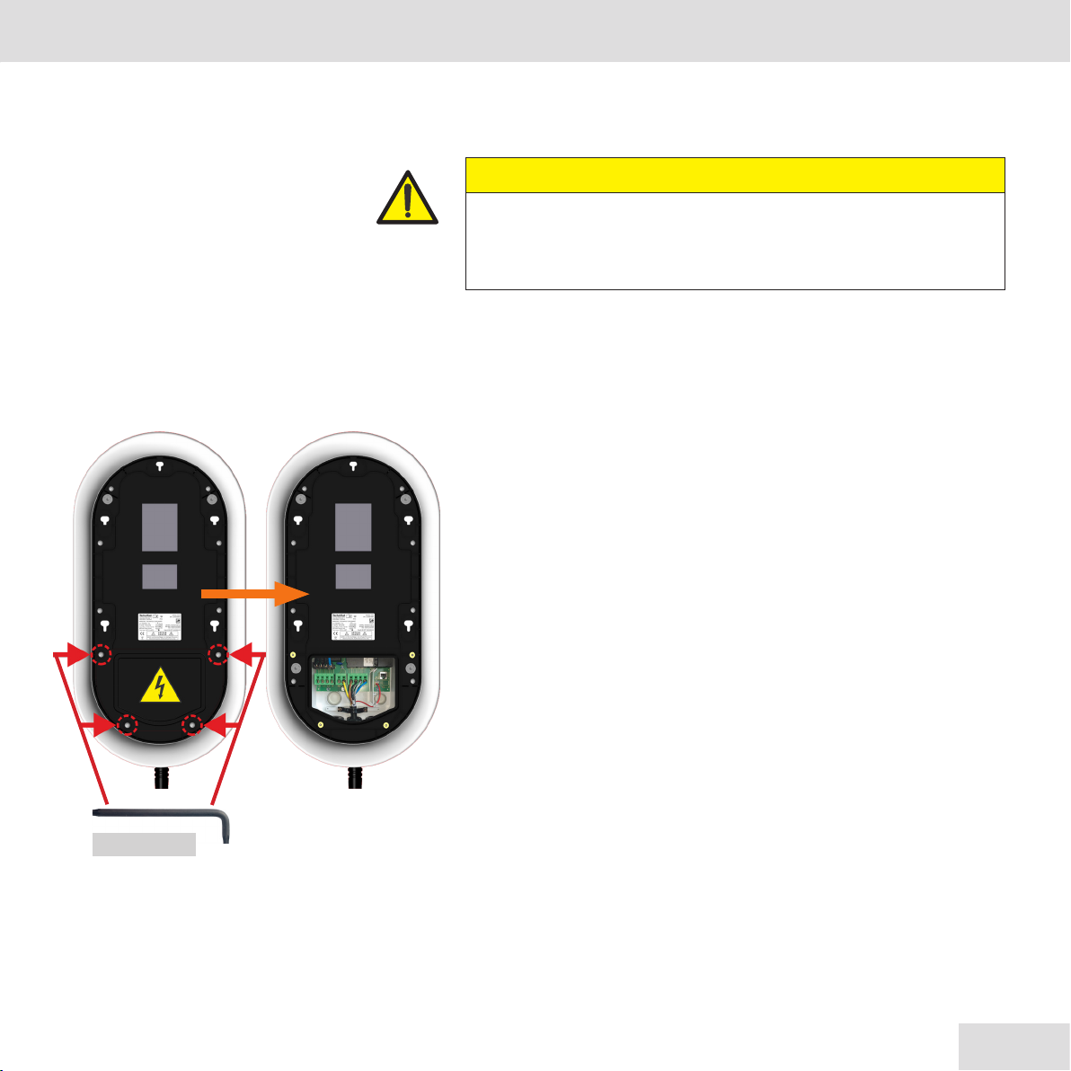
Removing the installation flap
Remove the installation flap of the charging station to access the
connection points later during the installation process.
hCompletely loosen the 4 screws marked in red in the fig. on the
le, using the Torx-TX 20 angle wrench to remove the installation
flap.
This gives you access to the mains connection terminal and the
Ethernet connection.
CAUTION
Risk of injury due to the charging station falling down
hAssembly of the charging station requires at least 2 people.
Torx-TX 20
20
Installing the charging station
202200801 - 2238001000200
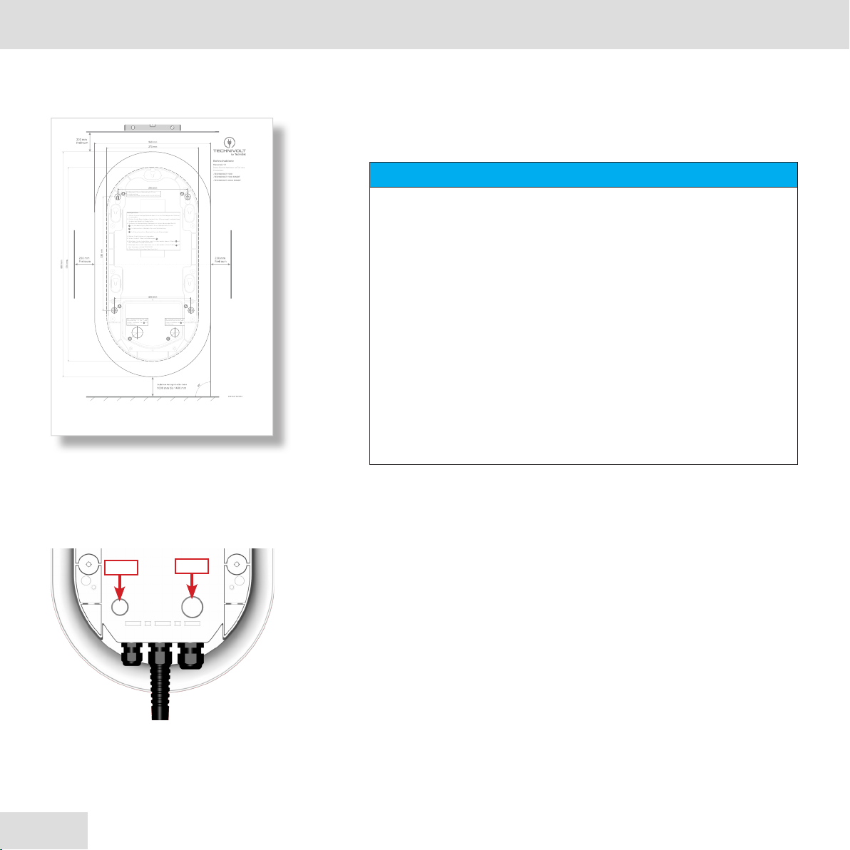
Wall mounting
Mount the charging station horizontally on the mounting surface.
1. Use the supplied drilling template to mark the fixing holes for wall
mounting.
2. Run the mains cable and, if necessary, the network cable (Ethernet)
up to the installation point of the charging station.
•If the cable is being fed through the back of the charging station,
the corresponding cable diaphragm bushings on the back of
the charging station must be pierced (see fig. on the le).
M32, cable diaphragm bushing for the mains supply line
M25, cable diaphragm bushing for the network cable
Use a pointed object, e.g. a small screwdriver, to pierce the
diaphragm.
Montagehinweis
1. WählenSie eine Montagefläche die eben ist um ein Durchbiegen des Gehäuses
zu vermeiden.
2. Richten Sie die Bohrschablone horizontal aus (Wasserwaage!) und befestigen
Sie diese bei Bedarf mit Klebestreifen.
3. Markieren Sie die benötigten Bohrlöcher mit einem Körner oder Bleisti:
4x, Wandbefestigung, Bohrloch Ø 8 mm, Bohrlochtiefe 70 mm.
1x, Netzanschluss, Bohrloch Ø je nach Netzzuleitung.
1x, Ethernetanschluss, Bohrloch Ø je nach Ethernetkabel.
4. Bohren Sie die Löcher wie angegeben.
5. Setzen Sie die 4 Dübel in die Bohrungen A.
6. Befestigen Sie die Ladestation zuerst an den beiden oberen Dübeln Amit
den Schrauben, Antrieb TX30/SW10.
7. Befestigen Sie nundie Ladestation nun an den beiden unteren Dübeln Amit
den Schrauben, Antrieb TX30/SW10.
8. Ziehen Sie alle 4 Schrauben überKreuz fest.
A
B
C
Bohrschablone
Massstab 1:1
Diese Bohrschablone ist Teil des
Produktes:
•TECHNIVOLT 1100
•TECHNIVOLT 1100SMART
•TECHNIVOLT 2200 SMART
4x Bohrloch Ø 8 mm, Bohrlochtiefe 70mm
Im Lieferumfang:
4x Dübel/Schrauben, FischerSXRL 8 x 60 FUS A4
Bei Unterputzzuführung der
Netzzuleitung in die Lade-
station, markieren Sie Bfür
die Bohrung.
Bei Unterputzzuführung der
Ethernetleitung in die Lade-
station, markieren Sie Cfür
die Bohrung.
NOTE
Follow the installation instructions on the drilling template!
hChoose a mounting surface that is level to avoid bending the
enclosure.
hAlign the drilling template horizontally with a spirit level and
secure it with adhesive tape if necessary.
hMark the required drill holes with a centre punch or pencil. If
the mains cable or Ethernet connection are inserted via the
rear of the charging station (flush-mounted feed), mark these
positions as well.
hDrill all holes as indicated on the drilling template.
M32
M25
View from the rear
Other manuals for 1100
1
This manual suits for next models
2
Table of contents


