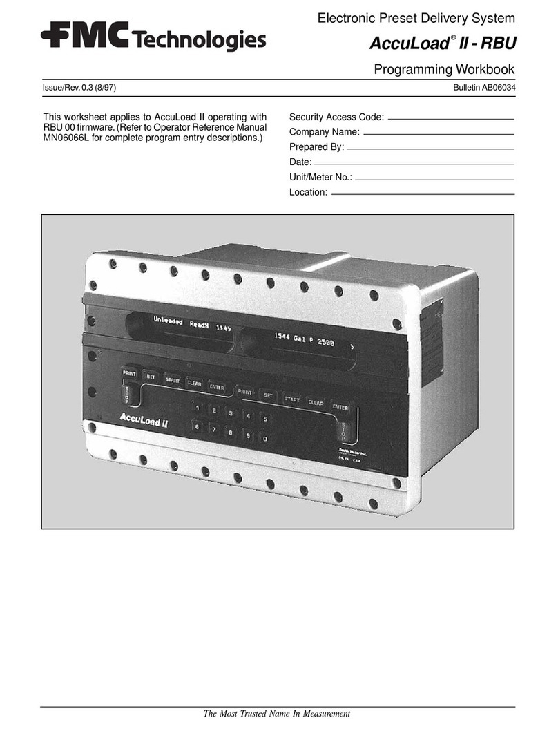
FMC Technologies AccuLoad II Owner's manual

Programming Workbook
Electronic Preset Delivery System
AccuLoad II - SEQ
®®
®®
®
This worksheet applies to AccuLoad II operating with
SEQ-00 and above firmware. (Refer to Operator Ref-
erence Manual MN06054L for complete program entry
descriptions.)
Security Access Code:
Company Name:
Prepared By:
Date:
Unit/Meter No.:
Location:
Issue/Rev. 0.6 (5/96) Bulletin AB06030
The Most Trusted Name In Measurement

ii
Table of Contents
System Directories.................................................................................................................................................2
System Configuration Directory................................................................................................................2
System General Purpose Directory..........................................................................................................8
System Flow Control Directory...............................................................................................................11
System Volume Accuracy Directory.......................................................................................................14
System Temperature & Density Directory ..............................................................................................17
System Pressure Directory ....................................................................................................................18
System Read Only Directory..................................................................................................................19
System Communication Directory..........................................................................................................19
System Input/Output Directory...............................................................................................................27
System Diagnostic Directory..................................................................................................................31
Product Directories ..............................................................................................................................................33
Product General Purpose Directory........................................................................................................33
Product Flow Control Directory ..............................................................................................................33
Volume Accuracy Directory....................................................................................................................34
Temperature & Density Directory...........................................................................................................35
Pressure Directory.................................................................................................................................37
Read Only Directory...............................................................................................................................39
Communications Directory.....................................................................................................................39
Inputs & Outputs Directory.....................................................................................................................40
Diagnostics Directory.............................................................................................................................40
Blend Recipe Directories ......................................................................................................................................41
Blend Recipe # __ Directory...................................................................................................................41

iii
Configuration
General Purpose
Flow Control
Volume Accuracy
Temp. & Density
Pressure
Read Only
Communications
Input/Output
Configuration
System
General Purpose
Flow Control
Volume Accuracy
Temp & Density
Pressure
Read Only
Communications
Input/Output
Diagnostics
Product 1
General Purpose
Flow Control
Volume Accuracy
Temp. & Density
Pressure
Read Only
Communications
Input/Output
Diagnostics
Product 2
General Purpose
Flow Control
Volume Accuracy
Temp. & Density
Pressure
Read Only
Communications
Input/Output
Diagnostics
Product 3
General Purpose
Flow Control
Volume Accuracy
Temp. & Density
Pressure
Read Only
Communications
Input/Output
Diagnostics
Product 4
Recipe 1
through
Recipe 24
Blend Recipe
Directories

Program Program
Code Function Code Description Entry Code
2AB06030 Rev. 0.6 5/96
System Directories
000 System Configuration Directory 000
001 Number of Products Enter: "1" One (1) Product 001
"2" Two (2) Products
"3" Three (3) Products
"4" Four (4) Products __
002 Number of Additive Enter: "0" No Additive Injectors 002
Injectors "1" One (1) Additive Injector
"2" Two (2) Additive Injectors
"3" Three (3) Additive Injectors
"4" Four (4) Additive Injectors
"5" Five (5) Additive Injectors
"6" Six (6) Additive Injectors
"7" Seven (7) Additive Injectors __
003 A/C Output Relay 1 Enter: "00" No Assignment (NAS) 003
Terminals 89 & 90 "01" Alarm Relay (ALR)
(Position #1) "02" Additive Relay 1 (ADD1)
Terminals 124 & 125 "03" Additive Relay 2 (ADD2)
(Position #2) "04" Additive Relay 3 (ADD3)
"05" Additive Relay 4 (ADD4)
"06" Additive Relay 5 (ADD5)
"07" Additive Relay 6 (ADD6)
"08" Additive Relay 7 (ADD7)
"09" Block Valve Relay 1 (BVR1)
"10" Block Valve Relay 2 (BVR2)
"11" Block Valve Relay 3 (BVR3)
"12" Block Valve Relay 4 (BVR4)
"13" General Relay (GEN)
"14" First Trip Indicator (FTR) __ __
Note: 1. Option "14" First Trip Indicator of this code applies to SEQ-06 and above firmware.
2. When using a Smart Additive Subsystem, options 02 through 08 (Additive Relays) are not available for selection.
004 A/C Output Relay 2 Enter: "00" No Assignment (NAS) 004
Terminals 91 & 92 "01" Alarm Relay (ALR)
(Position #1) "02" Additive Relay 1 (ADD1)
Terminals 126 & 127 "03" Additive Relay 2 (ADD2)
(Position #2) "04" Additive Relay 3 (ADD3)
"05" Additive Relay 4 (ADD4)
"06" Additive Relay 5 (ADD5)
"07" Additive Relay 6 (ADD6)
"08" Additive Relay 7 (ADD7)
"09" Block Valve Relay 1 (BVR1)
"10" Block Valve Relay 2 (BVR2)
"11" Block Valve Relay 3 (BVR3)
"12" Block Valve Relay 4 (BVR4)
"13" General Relay (GEN)
"14" First Trip Indicator (FTR) __ __
Note: 1. Option "14" First Trip Indicator of this code applies to SEQ-06 and above firmware.
2. When using a Smart Additive Subsystem, options 02 through 08 (Additive Relays) are not available for selection.

Program Program
Code Function Code Description Entry Code
AB06030 Rev. 0.6 5/96 3
005 A/C Output Relay 3 Enter: "00" No Assignment (NAS) 005
Terminals 93 & 94 "01" Alarm Relay (ALR)
(Position #1) "02" Additive Relay 1 (ADD1)
Terminals 128 & 129 "03" Additive Relay 2 (ADD2)
(Position #2) "04" Additive Relay 3 (ADD3)
"05" Additive Relay 4 (ADD4)
"06" Additive Relay 5 (ADD5)
"07" Additive Relay 6 (ADD6)
"08" Additive Relay 7 (ADD7)
"09" Block Valve Relay 1 (BVR1)
"10" Block Valve Relay 2 (BVR2)
"11" Block Valve Relay 3 (BVR3)
"12" Block Valve Relay 4 (BVR4)
"13" General Relay (GEN)
"14" First Trip Indicator (FTR) __ __
Note: 1. Option "14" First Trip Indicator of this code applies to SEQ-06 and above firmware.
2. When using a Smart Additive Subsystem, options 02 through 08 (Additive Relays) are not available for selection.
006 A/C Output Relay 4 Enter: "00" No Assignment (NAS) 006
Terminals 95 & 96 "01" Alarm Relay (ALR)
(Position #1) "02" Additive Relay 1 (ADD1)
Terminals 130 & 131 "03" Additive Relay 2 (ADD2)
(Position #2) "04" Additive Relay 3 (ADD3)
"05" Additive Relay 4 (ADD4)
"06" Additive Relay 5 (ADD5)
"07" Additive Relay 6 (ADD6)
"08" Additive Relay 7 (ADD7)
"09" Block Valve Relay 1 (BVR1)
"10" Block Valve Relay 2 (BVR2)
"11" Block Valve Relay 3 (BVR3)
"12" Block Valve Relay 4 (BVR4)
"13" General Relay (GEN)
"14" First Trip Indicator (FTR) __ __
Note: 1. Option "14" First Trip Indicator of this code applies to SEQ-06 and above firmware.
2. When using a Smart Additive Subsystem, options 02 through 08 (Additive Relays) are not available for selection.
007 A/C Output Relay 5 Enter: "00" No Assignment (NAS) 007
Terminals 87 & 88 "01" Alarm Relay (ALR)
(Position #1) "02" Additive Relay 1 (ADD1)
Terminals 121 & 122 "03" Additive Relay 2 (ADD2)
(Position #2) "04" Additive Relay 3 (ADD3)
"05" Additive Relay 4 (ADD4)
"06" Additive Relay 5 (ADD5)
"07" Additive Relay 6 (ADD6)
"08" Additive Relay 7 (ADD7)
"09" Block Valve Relay 1 (BVR1)
"10" Block Valve Relay 2 (BVR2)
"11" Block Valve Relay 3 (BVR3)
"12" Block Valve Relay 4 (BVR4) __ __
Note: When using a Smart Additive Subsystem, options 02 through 08 (Additive Relays) are not available for selection.

Program Program
Code Function Code Description Entry Code
4AB06030 Rev. 0.6 5/96
008 D/C Output Relay 1 Enter: "00" No Assignment (NAS) 008
W/O Quad OPV "01" Pulse Output (POT)
Terminals 9 & 10 "02" Additive Relay 1 (ADD1)
(Position #1) "03" Additive Relay 2 (ADD2)
Terminals 57 & 58 "04" Additive Relay 3 (ADD3)
(Position #2) "05" Additive Relay 4 (ADD4)
"06" Additive Relay 5 (ADD5)
W/Quad OPV "07" Additive Relay 6 (ADD6)
Terminals 11 & 10 "08" Additive Relay 7 (ADD7)
(Position #1) "09" Block Valve Relay 1 (BVR1)
Terminals 15 & 14 "10" Block Valve Relay 2 (BVR2)
(Position #2) "11" Block Valve Relay 3 (BVR3)
"12" Block Valve Relay 4 (BVR4) __ __
Note: When using a Smart Additive Subsystem, options 02 through 08 (Additive Relays) are not available for selection.
009 D/C Output Relay 2 Enter: "00" No Assignment (NAS) 009
W/Quad OPV "01" Pulse Output (POT)
Terminals 13 & 12 "02" Additive Relay 1 (ADD1)
(Position #1) "03" Additive Relay 2 (ADD2)
Terminals 17 & 16 "04" Additive Relay 3 (ADD3)
(Position #2) "05" Additive Relay 4 (ADD4)
"06" Additive Relay 5 (ADD5)
"07" Additive Relay 6 (ADD6)
"08" Additive Relay 7 (ADD7)
"09" Block Valve Relay 1 (BVR1)
"10" Block Valve Relay 2 (BVR2)
"11" Block Valve Relay 3 (BVR3)
"12" Block Valve Relay 4 (BVR4) __ __
Note: 1. This code is only available for use if the Quad OPV option has been purchased with the AccuLoad II. The terminals listed for this
code are located on the Quad OPV board.
2. When using a Smart Additive Subsystem, options 02 through 08 (Additive Relays) are not available for selection.
010 A/C Input 1 Enter: "00" No Assignment (NAS) 010
Terminals 98 & 101 "01" Additive Feedback 1 (AFB1)
(Position #1) "02" Additive Feedback 2 (AFB2)
Terminals 106 & 109 "03" Additive Feedback 3 (AFB3)
(Position #2) "04" Additive Feedback 4 (AFB4)
"05" Additive Feedback 5 (AFB5)
"06" Additive Feedback 6 (AFB6)
"07" Additive Feedback 7 (AFB7)
"08" Block Valve Feedback 1 (BVF1)
"09" Block Valve Feedback 2 (BVF2)
"10" Block Valve Feedback 3 (BVF3)
"11" Block Valve Feedback 4 (BVF4)
"12" First/Second High Flow (FSC)
"13" Printer Tray Switch (PTS) *
"14" Permissive 1 Contact (PRC1)
"15" Permissive 2 Contact (PRC2)
"16" Valve Power (VPW)
"17" Valve Stem (VST) __ __
Note: 1. Or can be used for Master Reset.*
2. When using a Smart Additive Subsystem, options 01 through 07 (Additive Feedbacks) are not available for selection.

Program Program
Code Function Code Description Entry Code
AB06030 Rev. 0.6 5/96 5
011 A/C Input 2 Enter: "00" No Assignment (NAS) 011
Terminals 99 & 101 "01" Additive Feedback 1 (AFB1)
(Position #1) "02" Additive Feedback 2 (AFB2)
Terminals 107 & 109 "03" Additive Feedback 3 (AFB3)
(Position #2) "04" Additive Feedback 4 (AFB4)
"05" Additive Feedback 5 (AFB5)
"06" Additive Feedback 6 (AFB6)
"07" Additive Feedback 7 (AFB7)
"08" Block Valve Feedback 1 (BVF1)
"09" Block Valve Feedback 2 (BVF2)
"10" Block Valve Feedback 3 (BVF3)
"11" Block Valve Feedback 4 (BVF4)
"12" First/Second High Flow (FSC)
"13" Printer Tray Switch (PTS) *
"14" Permissive 1 Contact (PRC1)
"15" Permissive 2 Contact (PRC2)
"16" Valve Power (VPW)
"17" Valve Stem (VST) __ __
Note: 1. Or can be used for Master Reset.*
2. When using a Smart Additive Subsystem, options 01 through 07 (Additive Feedbacks) are not available for selection.
012 A/C Input 3 Enter: "00" No Assignment (NAS) 012
Terminals 100 & 101 "01" Additive Feedback 1 (AFB1)
(Position #1) "02" Additive Feedback 2 (AFB2)
Terminals 108 & 109 "03" Additive Feedback 3 (AFB3)
(Position #2) "04" Additive Feedback 4 (AFB4)
"05" Additive Feedback 5 (AFB5)
"06" Additive Feedback 6 (AFB6)
"07" Additive Feedback 7 (AFB7)
"08" Block Valve Feedback 1 (BVF1)
"09" Block Valve Feedback 2 (BVF2)
"10" Block Valve Feedback 3 (BVF3)
"11" Block Valve Feedback 4 (BVF4)
"12" First/Second High Flow (FSC)
"13" Printer Tray Switch (PTS) *
"14" Permissive 1 Contact (PRC1)
"15" Permissive 2 Contact (PRC2)
"16" Valve Power (VPS)
"17" Valve Stem (VST) __ __
Note: 1. Or can be used for Master Reset.*
2. When using a Smart Additive Subsystem, options 01 through 07 (Additive Feedbacks) are not available for selection.

Program Program
Code Function Code Description Entry Code
6AB06030 Rev. 0.6 5/96
013 A/C Input 4 Enter: "00" No Assignment (NAS) 013
Terminals 103 & 105 "01" Additive Feedback 1 (AFB1)
(Position #1) "02" Additive Feedback 2 (AFB2)
Terminals 110 & 112 "03" Additive Feedback 3 (AFB3)
(Position #2) "04" Additive Feedback 4 (AFB4)
"05" Additive Feedback 5 (AFB5)
"06" Additive Feedback 6 (AFB6)
"07" Additive Feedback 7 (AFB7)
"08" Block Valve Feedback 1 (BVF1)
"09" Block Valve Feedback 2 (BVF2)
"10" Block Valve Feedback 3 (BVF3)
"11" Block Valve Feedback 4 (BVF4)
"12" First/Second High Flow (FSC)
"13" Printer Tray Switch (PTS) *
"14" Permissive 1 Contact (PRC1)
"15" Permissive 2 Contact (PRC2)
"16" Valve Power (VPS)
"17" Valve Stem (VST) __ __
Note: 1. Or can be used for Master Reset.*
2. For "Remote Start" operation this code must be programmed "14" (Permissive Contact #1), code 806 must be programmed "5"
(Remote Start) and jumpers must be installed as shown in the Installation Manual (MN06037).
3. When using a Smart Additive Subsystem, options 01 through 07 (Additive Feedbacks) are not available for selection.
014 A/C Input 5 Enter: "00" No Assignment (NAS) 014
Terminals 104 & 105 "01" Additive Feedback 1 (AFB1)
(Position #1) "02" Additive Feedback 2 (AFB2)
Terminals 111 & 112 "03" Additive Feedback 3 (AFB3)
(Position #2) "04" Additive Feedback 4 (AFB4)
"05" Additive Feedback 5 (AFB5)
"06" Additive Feedback 6 (AFB6)
"07" Additive Feedback 7 (AFB7)
"08" Block Valve Feedback 1 (BVF1)
"09" Block Valve Feedback 2 (BVF2)
"10" Block Valve Feedback 3 (BVF3)
"11" Block Valve Feedback 4 (BVF4)
"12" First/Second High Flow (FSC)
"13" Printer Tray Switch (PTS) *
"14" Permissive 1 Contact (PRC1)
"15" Permissive 2 Contact (PRC2)
"16" Valve Power (VPS)
"17" Valve Stem (VST) __ __
Note: 1. Or can be used for Master Reset.*
2. For "Remote Stop" operation this code must be programmed "15" (Permissive 2 Contact), code 810 must be programmed "5"
(Remote Stop) and jumpers must be installed as shown in the Installation Manual (MN06037).
3. When using a Smart Additive Subsystem, options 01 through 07 (Additive Feedbacks) are not available for selection.

Program Program
Code Function Code Description Entry Code
AB06030 Rev. 0.6 5/96 7
015 A/C Input 6 Enter: "00" No Assignment (NAS) 015
Terminals 73 & 74 "01" Additive Feedback 1 (AFB1)
(Position #1) "02" Additive Feedback 2 (AFB2)
Terminals 75 & 76 "03" Additive Feedback 3 (AFB3)
(Position #2) "04" Additive Feedback 4 (AFB4)
"05" Additive Feedback 5 (AFB5)
"06" Additive Feedback 6 (AFB6)
"07" Additive Feedback 7 (AFB7)
"08" Block Valve Feedback 1 (BVF1)
"09" Block Valve Feedback 2 (BVF2)
"10" Block Valve Feedback 3 (BVF3)
"11" Block Valve Feedback 4 (BVF4)
"12" First/Second High Flow (FSC)
"13" Printer Tray Switch (PTS) *
"14" Permissive 1 Contact (PRC1)
"15" Permissive 2 Contact (PRC2)
"16" Valve Power (VPW)
"17" Valve Stem (VST)
Note: 1. Or can be used for Master Reset.*
2. When using a Smart Additive Subsystem, options 01 through 07 (Additive Feedbacks) are not available for selection.
016-039 Unassigned at Present 016-039
040 Print Enter: Press ‘ENTER’ to Print 040
Configuration Configuration Report.
Note: Configuration Report will print for both preset positions.
041 Additive System Enter: "0" Piston Injectors 041
and Pacing Control "1" Titan w/Pulse
Selection "2" Titan w/Comm
"3" Gate City w/Pulse
"4" Gate City w/Comm __
Note: This code applies to SEQ-13 and above firmware.
042-089 Unassigned at Present 042-089
090 Input/Output Enter: "1" One Product 090
Configuration "2" Two Products
"3" Three Products
"4" Four Products __
Note: Entering the above number will program the AccuLoad II to a typical Input and Output configuration for the number of products selected.
Refer to manual MN06054L for input & output assignments when using this method of configuring the AccuLoad II - SEQ.
Caution: This code will override anything that is currently programmed in the configuration directory. Do
not use this code if you have already configured the unit.
091-099 Unassigned at Present 091-099

Program Program
Code Function Code Description Entry Code
8AB06030 Rev. 0.6 5/96
100
System General Purpose Directory
100
101 System Alarm Check/Reset Read only, Press E to clear None 101
Available Alarms
AC: Additive Communications** L5: Additive 5 Pulse**
A2: Print Cover Open L6: Additive 6 Pulse**
A4: Print Cover Open L7: Additive 7 Pulse**
B2: Buffer Overflow M1: Too Many Pulses Additive 1**
B4: Buffer Overflow M2: Too Many Pulses Additive 2**
CL: Clean Line M3: Too Many Pulses Additive 3**
CM: Communication M4: Too Many Pulses Additive 4**
DA: EEProm Bad M5: Too Many Pulses Additive 5**
DA: Ram Bad M6: Too Many Pulses Additive 6**
DA: Rom Uxx Bad M7: Too Many Pulses Additive 7**
DA: Watchdog Alarm N1: No Pulses Detected Address 1**
DA: Display Error N2: No Pulses Detected Address 2**
DA: Data Retention N3: No Pulses Detected Address 3**
DA: Display Boot Required N4: No Pulses Detected Address 4**
DA: Control Module N5: No Pulses Detected Address 5**
DA: Security Code N6: No Pulses Detected Address 6**
DA: Software Version N7: No Pulses Detected Address 7**
DA: Internal Temperature OA: Overrun
DA: Program Code O2: Printer Paper Out
DP: Down Pulse Error O4: Printer Paper Out
DR: Density Transducer PA: Power Fail*
D2: Printer Deselected PC: Pulse Collision
D4: Printer Deselected PR: Pressure Transducer
E2: Printer Error PS: Pulse Security
E4: Printer Error PT: Pulse Transmission
F1: Add 1 Feedback P2: Printer Communication
F2: Add 2 Feedback P4: Printer Communication
F3: Add 3 Feedback R1: Additive 1 Frequency**
F4: Add 4 Feedback R2: Additive 2 Frequency**
F5: Add 5 Feedback R3: Additive 3 Frequency**
F6: Add 6 Feedback R4: Additive 4 Frequency**
F7: Add 7 Feedback R5: Additive 5 Frequency**
H2: Printer Hardware R6: Additive 6 Frequency**
H4: Printer Hardware R7: Additive 7 Frequency**
IA: Injector Alarm** SF: Storage Full
I2: Printer Not Responding SP: Shared Printer
I4: Printer Not Responding TK: Ticket Alarm
K1: Low Additive 1** TP: Temperature Probe
K2: Low Additive 2** TT: Temperature Transducer
K3: Low Additive 3** U1: Unauthorize Command Failed Additive 1**
K4: Low Additive 4** U2: Unauthorize Command Failed Additive 2**
K5: Low Additive 5** U3: Unauthorize Command Failed Additive 3**
K6: Low Additive 6** U4: Unauthorize Command Failed Additive 4**
K7: Low Additive 7** U5: Unauthorize Command Failed Additive 5**
L1: Additive 1 Pulse** U6: Unauthorize Command Failed Additive 6**
L2: Additive 2 Pulse** U7: Unauthorize Command Failed Additive 7**
L3: Additive 3 Pulse** VF: Valve Fault
L4: Additive 4 Pulse** ZF: Zero Flow*
Note: * These alarms apply to SEQ-11 and above firmware.
** These alarms apply to SEQ-13 and above firmware.

Program Program
Code Function Code Description Entry Code
AB06030 Rev. 0.6 5/96 9
102 Product 1 Alarm Check/Reset Read only, Press E to clear None 102
Available Alarms
BH: Blend High HP: High Pressure
BL: Blend Low HT: High Temperature
BP: Back Pressure LD: Low Density
BV: Block Valve Fault LF: Low Flow
HD: High Density LP: Low Pressure
HF: Excess High Flow LT: Low Temperature
103 Product 2 Alarm Check/Reset Read only, Press E to clear None 103
Available Alarms
BH: Blend High HP: High Pressure
BL: Blend Low HT: High Temperature
BP: Back Pressure LD: Low Density
BV: Block Valve Fault LF: Low Flow
HD: High Density LP: Low Pressure
HF: Excess High Flow LT: Low Temperature
104 Product 3 Alarm Check/Reset Read only, Press E to clear None 104
Available Alarms
BH: Blend High HP: High Pressure
BL: Blend Low HT: High Temperature
BP: Back Pressure LD: Low Density
BV: Block Valve Fault LF: Low Flow
HD: High Density LP: Low Pressure
HF: Excess High Flow LT: Low Temperature
105 Product 4 Alarm Check/Reset Read only, Press E to clear None 105
Available Alarms
BH: Blend High HP: High Pressure
BL: Blend Low HT: High Temperature
BP: Back Pressure LD: Low Density
BV: Block Valve Fault LF: Low Flow
HD: High Density LP: Low Pressure
HF: Excess High Flow LT: Low Temperature
106 Blend Alarms Check/Reset Read only, Press E to clear None 106
Available Alarms
DA: Program Code
107 Transaction Alarms To be read only None 107
108 Ready Mode Alarms To be read only None 108

Program Program
Code Function Code Description Entry Code
10 AB06030 Rev. 0.6 5/96
109 Set Time Enter: Five (5) digits. Two (2) digits 109
for hours, Two (2) digits for minutes
and one (1) to indicate military,
time, AM or PM. The last digit will
be "0" = AM, "1" = PM and
"2" = Military (e.g., 01:130) __ __ __ __ __
110 Set Date Enter: Six (6) digits. Two (2) digits for 110
month followed by two (2) digits for
day, followed by (2) digits for
year (e.g., 011288) __ __ __ __ __ __
111 Dynamic Display Enter: Two (2) digits in seconds 111
Time-out of time-out (e.g., 15)
"00" Display will remain till
the "CLEAR" key is pressed __ __
112-139 Unassigned at Present 112-139
140 Protection of Program Enter: "0" for Weights and Measures Mode 140
Codes 180-189 "1" for Program Mode __
141 Local Mode Alarm Enter: One (1) digit from one (1) to 141
Clearing nine (9) indicates the number
of alarms that can be cleared
during a transaction when
in the Run & Ready Mode. (e.g., 3) __
142 Decimal or Comma Enter: "0" Decimal 142
Selection "1" Comma __
143 Alarm Relay Enter: "0" Alarm Relay on Valve Fault 143
"1" Alarm Relay on Any Fault
"2" No Alarm Relay __
144 Run & Ready Mode Enter: "0" English 144
Initialization "1" Not Used
"2" Spanish __
Note: Entry "1" is reserved for future use and is not allowed by the AccuLoad II.
Note: This code applies to SEQ-09 and above firmware.
145 Ready/Run Mode Enter: The number of the alarm that is to 145
Clearable Alarms to be changed (see Appendix for the
Selection alarms, associated numbers and recording
entries.) When the alarm is displayed
enter a "0" if the alarm is allowed to be
cleared in the Ready/Run Mode. Enter a "1"
if the alarm is not allowed to be cleared
in the Ready/Run Mode.
Note: 1. If code 141 is set to "0" the message "No Alarm Clearing" will be displayed and no entries will be allowed.
2. This code applies to SEQ-11 and above firmware.
146-179 Unassigned at Present 146-179
180 Programming Access Enter: Four digit number permits 180
Code entry in to the Program or Weights
and Measures Mode (e.g., 1234) __ __ __ __

Program Program
Code Function Code Description Entry Code
AB06030 Rev. 0.6 5/96 11
181 Transaction Security Enter: Eight (8) digit transaction 181
ID ID number (e.g., 12345678)
"00000000" disables this feature.
__ __ __ __ __ __ __ __
182 Transaction Security Enter: Up to twenty (20) characters 182
Prompt Message for a prompt message
(e.g., Enter ID Number)
____________________
183 Auto Reset Timer Enter: Two (2) digit number in 183
minutes that the AccuLoad II
will remain in the a mode of
operation before automatically
returning to the Ready Mode (e.g., 05)
"00" disables this feature. __ __
184 Ready Mode Enter: Up to Fifteen (15) characters 184
Message for a prompt message
(e.g., Load Arm #1) _________________
185 Run & Ready Mode Enter: The number of the display 185
Customized Display that you want to change.
Press ‘ENTER’. The default
display will appear for that
number or you can scroll through
the displays by pressing the
‘ENTER’ key. The display can
be changed using the character set
resident in the AccuLoad II. (See
Appendix for entry numbers and
to record translation.)
Note: This code applies to SEQ-09 and above firmware.
186 Power-fail Alarm Enter: "0" Power-fail Alarm Disabled 186
"1" Power-fail Alarm Enabled __
Note: This code applies to SEQ-11 and above firmware.
187-189 Unassigned at Present 187-189
190 Meter Position Enter: "0" Meter Enabled 190
Disable "1" Meter Disabled __
191-199 Unassigned at Present 191-199
200
System Flow Control Directory
200
201 Low Flow Start Volume Enter: Four (4) digits in whole 201
units (e.g., 0100) __ __ __ __
202 Low Flow Start Rate Enter: Four (4) digits in whole 202
units per minute (e.g., 0150)
"0000" entry will not allow
the valve to open. __ __ __ __
203 Low Flow Start Enter: "0" Low Flow Start always after 203
"START" is pressed.
"1" Low Flow Start at beginning
of batch only. ___

Program Program
Code Function Code Description Entry Code
12 AB06030 Rev. 0.6 5/96
204 Zero Flow Timer Enter: Two (2) digits in seconds (e.g., 15) 204
"00" disables this option __ __
205 Overrun Alarm Limit Enter: Two (2) digits in whole 205
units (e.g., 15)
"00" disables the alarm __ __
206 Start Delay After Stop Enter: Three (3) digits in whole 206
seconds of delay time
(e.g., 020) __ __ __
207 Pump Relay Time Enter: Two (2) digits in 207
Delay seconds of delay time
(e.g., 09) __ __
208 Valve Delay To Open Enter: Two (2) digits in seconds 208
of delay time. (e.g., 07)
"00" disables option __ __
209 PT/VF Time Delay Enter: Two (2) digits in seconds 209
of time delay (e.g., 15)
Entry must not be "00" __ __
210 Flow Control Valve Enter: "0" for a Digital Valve 210
"1" for a Two-stage Valve __
211 Zero Flow Alarm Enter: "0" Zero Flow Alarm Disabled 211
"1" Zero Flow Alarm Enabled __
Note: This code applies to SEQ-11 and above firmware.
212-239 Unassigned at Present 212-239
240 Protection of Program Enter: "0" for Weights and Measures Mode 240
Codes 280-289 "1" for Program Mode __
241 Flow Control Valve Enter: "0" for No Security 241
Security "1" for Security __
242-279 Unassigned at Present 242-279
280 Clean Line Product Enter: "1" for Product 1 280
"2" for Product 2
"3" for Product 3
"4" for Product 4 __
281 Clean Line Volume Enter: Three (3) digits in whole 281
units of product to be left
in the line at the end of
the batch. (e.g., 050) __ __ __
Note: The Clean Line Volume is always subtracted from 1st product in the recipe
282 Clean Line Alarm Enter: Two (2) digits in volume 282
Limit of under delivery of the
clean line volume allowed.
(e.g., 10) __ __

Program Program
Code Function Code Description Entry Code
AB06030 Rev. 0.6 5/96 13
283 Block Valve Enter: "0" Valve off SP & ET 283
Position "1" Valve on SP, off ET
"2" Valve off SP, on ET
"3" Valve on SP & ET __
Note: ET = End of Transaction and SP = Stop is Pressed
284-299 Unassigned at Present 284-299

Program Program
Code Function Code Description Entry Code
14 AB06030 Rev. 0.6 5/96
300
System Volume Accuracy Directory
300
301 Transaction Control Enter: "0" Local Tray Switch 301
"1" Print Key
"2" Remote
"3" Master Reset __
302 Maximum Preset Enter: Five (5) digits in whole units 302
Volume (e.g., up to 99,999 units)
"00000" disables option __ __ __ __ __
303 Minimum Preset Enter: Five (5) digits in whole units 303
Volume (e.g., up to 99,999 units)
"00000" disables option __ __ __ __ __
304 Auto Preset Enter: Five (5) digits in whole units 304
(e.g., 99,999 units)
"00000" disables option __ __ __ __ __
305 Auto Preset Increment Enter: Four (4) digits in whole units 305
to increment the auto preset.
(e.g., 0100 units)
"0000" disables option __ __ __ __
306 Blank Downcounter Enter: "0" Downcounter to be Displayed 306
"1" No Downcounter Displayed __
307 Volumes for Local Enter: Five (5) digit number indicating 307
Storage the volumes that will be stored in
local storage.
Note: A maximum of three (3) volumes will be stored.
1st digit - Raw Volumes (RW)
2nd digit - Gross Volumes (GR)
3rd digit - Gross at Standard Temperature
Volumes (GT)
4th digit - Net Volumes (NT)
5th digit - Mass Totals (MA)
A zero (0) in the digit indicates that
the volume will not be saved in local
storage, a (1) indicates the volume
will be saved in local storage. __ __ __ __ __
308-339 Unassigned at Present 308-339
340 Protection of Program Enter: "0" for Weights and Measures Mode 340
Codes 380-389 "1" for Program Mode __

Program Program
Code Function Code Description Entry Code
AB06030 Rev. 0.6 5/96 15
341 Dual Pulse Error Enter: Three (3) digits indicating 341
Count the number of error counts
from the Dual Pulse Comparator
prior to alarming. (e.g., 050) __ __ __
Note: "000" disables the error counting.
342 Dual Pulse Error Enter: "0" No DPC Error Reset 342
Reset "1" Reset at the End of Transaction Only
"2" Reset Upon Power-up Only
"3" Reset Upon Power-up and
at the End of Each Transaction __
343 Dual Pulse Flow Enter: Three (3) digits defining 343
Rate Cutoff the flow rate that the
Dual Pulse errors will begin
to be counted. __ __ __
344 Display Units Enter: Three (3) character message 344
identifying the display units
(e.g., GAL) __ __ __
345 Corrected Display Enter: "0" No Correction 345
"1" Correct Delivery Display
"2" Corrected Preset Display
"3" Corrected Delivery & Preset __
346 Pulse #1 Enter: "0" Raw Pulse Out 1 346
Output "1" Gross Pulse Out 1
"2" Gst Pulse Out 1
"3" Net Pulse Out 1
"4" Mass Pulse Out 1 __
347 Pulse #1 Output Enter: Four (4) digits defining 347
Resolution the pulse output resolution
(units/pulse) in tenth units,
"0000" Disables this feature
(e.g., 010.0) __ __ __ . __
Note: Input pulses must be 2.5 times greater than the output pulses (e.g., 100 output pulses/unit volume requires at least 250 input
pulses/unit volume).
348 Pulse #2 Enter: "0" Raw Pulse Out 2 348
Output "1" Gross Pulse Out 2
"2" Gst Pulse Out 2
"3" Net Pulse Out 2
"4" Mass Pulse Out 2 __

Program Program
Code Function Code Description Entry Code
16 AB06030 Rev. 0.6 5/96
349 Pulse #2 Output Enter: Four (4) digits defining 349
Resolution the pulse output resolution
(units/pulse) in tenth units,
"0000" Disables this feature
(e.g., 010.0) __ __ __ . __
Note: Input pulses must be 2.5 times greater than the output pulses (e.g., 100 output pulses/unit volume requires at least 250 input pulses/unit
volume).
350 Display Resolution Enter: "0" Whole Unit Display 350
"1" Tenth Unit Display
"2" Hundredth Unit Display
"3" Tens Unit Display __
351 Input Resolution Enter: Four (4) digit number representing 351
the number of pulses per unit of
registration (e.g., 0100)
Entry must be between 0025
and 9999 __ __ __ __
352 Proving Modes Enter: "0" Not Proving 352
"1" Weights and Measures Proving
"2" High Speed Proving __
353 Proving Output Enter: "0" No Prover Output 353
"1" Meter #1 Prover Output
"2" Meter #2 Prover Output __
354 Proving Output Units Enter: "0" Raw Prover Output (Raw) 354
"1" Gross Prover (Grs)
"2" Gross Prover at Standard Temperature (Gst)
"3" Gross Prover at Standard Temperature
and Pressure Preset (Net)
"4" Mass Preset (Whole Units) __
355 Blend Tolerance Enter: Two (2) digits in tenths of a 355
(Percentage) percentage for the tolerance
allowed for all delivered
blends. (e.g., 5.0 = 5 %) __ __
Note: The larger of the tolerances as calculated using the percentage entered in this code or the volume entered in code 357 will be used to
determine when a blend alarm should be triggered.
356 Blend Tolerance Enter: Three (3) digits of Volume for 356
(Volume) Blend Tolerance in tenths of units.
(e.g., 10.0) __.__
Note: The larger of the tolerances as programmed in this code or calculated in code 356 will be used to determine when a blend alarm will be
triggered.
357 Blend Correction Enter: "0" No Blend Correction 357
"1" Self-corrected Blend
"2" Self-corrected/Complete Blend __

Program Program
Code Function Code Description Entry Code
AB06030 Rev. 0.6 5/96 17
358 Recipes Per Enter: "0" Single Recipe/Transaction 358
Transaction "1" Multiple Recipes/Transaction __
359 Auto Proving Select Enter: "0" Auto Proving Disabled 359
"1" Auto Proving Enabled
"2" Auto Proving Always __
Note: This code applies to SEQ-12 and above firmware.
360-389 Unassigned at Present 360-389
390 Input Pulse Type Enter: "0" Active Pulse Input 390
"1" Contact Type Input __
391 Input Pulse Doubler Enter: "0" Pulses Times One 391
"1" Pulses Times Two __
392 Transmitter Type Enter: "0" Single Channel 392
"1" Single and Inverted
"2" Dual Channel
"3" Dual and Inverted __
393-399 Unassigned at Present 393-399
400
System Temperature & Density Directory
400
401-439 Unassigned at Present 401-439
440 Protection of Program Enter: "0" for Weights and Measures Mode 440
Codes 480-489 "1" for Program Mode __
441 Temperature Units Enter: "0" No Temperature Probe 441
"1" Fahrenheit
"2" Celsius __
442 Reference Enter: Four (4) digit reference 442
Temperature temperature in tenth degrees
(e.g., 060.0) __ __ __ . __
443 Temperature Offset Enter: Three (3) digits. First digit 443
must be "0" or "1" (0 = positive,
1 = negative). Second and third
digits represent the offset temperature
in tenth degrees (e.g., 10.5 entered
will display as -0.5 degrees offset) __ __ . __
444 Density or Enter: "0" Density Input 444
Temperature Input "1" Temperature Input __
Note: If Temperature is selected AccuLoad II will ignore the RTD channel. To accept readings from the RTD channel this entry must be selected
for density input.
445 Density Units Enter: "0" No Densitometer Installed 445
"1" Lbs/Ft3.
"2" Kgs/M3.__

Program Program
Code Function Code Description Entry Code
18 AB06030 Rev. 0.6 5/96
446 Minimum Density Enter: Five (5) digits. For 446
OR Minimum minimum density at 4 mA in
Temperature tenth units (e.g., 0100.0).
as selected in For minimum Temperature at 4 mA the
code 444 first digit indicates the polarity.
First digit "0" = Positive
First digit "1" = Negative
The last four digits indicate the
temperature in tenth degrees.
(e.g., 0030.0 = +030.0)
Temperature units as selected
in code 441. __ __ __ __ . __
447 Maximum Density Enter: Five (5) digits. For 447
OR Maximum maximum density at 20 mA in
Temperature tenth units (e.g., 1600.0).
as selected For maximum Temperature at 4 mA the
in code 444 first digit indicates the polarity.
First digit "0" = Positive
First digit "1" = Negative
The last four digits indicate the
temperature in tenth degrees.
(e.g., 0100.0 = +100.0)
Temperature units as selected
in code 441. An entry of -999.9
(Temperature) or 0000.0 (Density)
will disable this feature. __ __ __ __ . __
448 Volume/Mass Enter: "0" Gallons per Density Units 448
Conversion "1" Dekaliters per Density Units
"2" Liters per Density Units
"3" Barrels per Density Units
"4" Cubic Meters per Density Units __
449 Mass Units Enter: Three (3) character message 449
identifying the mass units
(e.g., Lbs) __ __ __
450-499 Unassigned at Present 450-499
500
System Pressure Directory
500
501-539 Unassigned at Present 501-539
540 Protection of Program Enter: "0" for Weights and Measures Mode 540
Codes 580-589 "1" for Program Mode __
541 Pressure Units Enter: "0" No Pressure Transducer Installed 541
"1" Psi
"2" Bar
"3" Kgcm __
542 Minimum Pressure Enter: Four (4) digits in tenth 542
Units units for minimum pressure
at 4 mA. (e.g., 1600 = 160.0)
Units dependent on selection
in code 541. __ __ __ . __
Other manuals for AccuLoad II
1
This manual suits for next models
1
Table of contents
Other FMC Technologies Controllers manuals
