FMC Technologies Smith Meter microFlow.net Liquid User manual
Bulletin MNFL003 ║ Issue/Rev 0.1 (9/13)
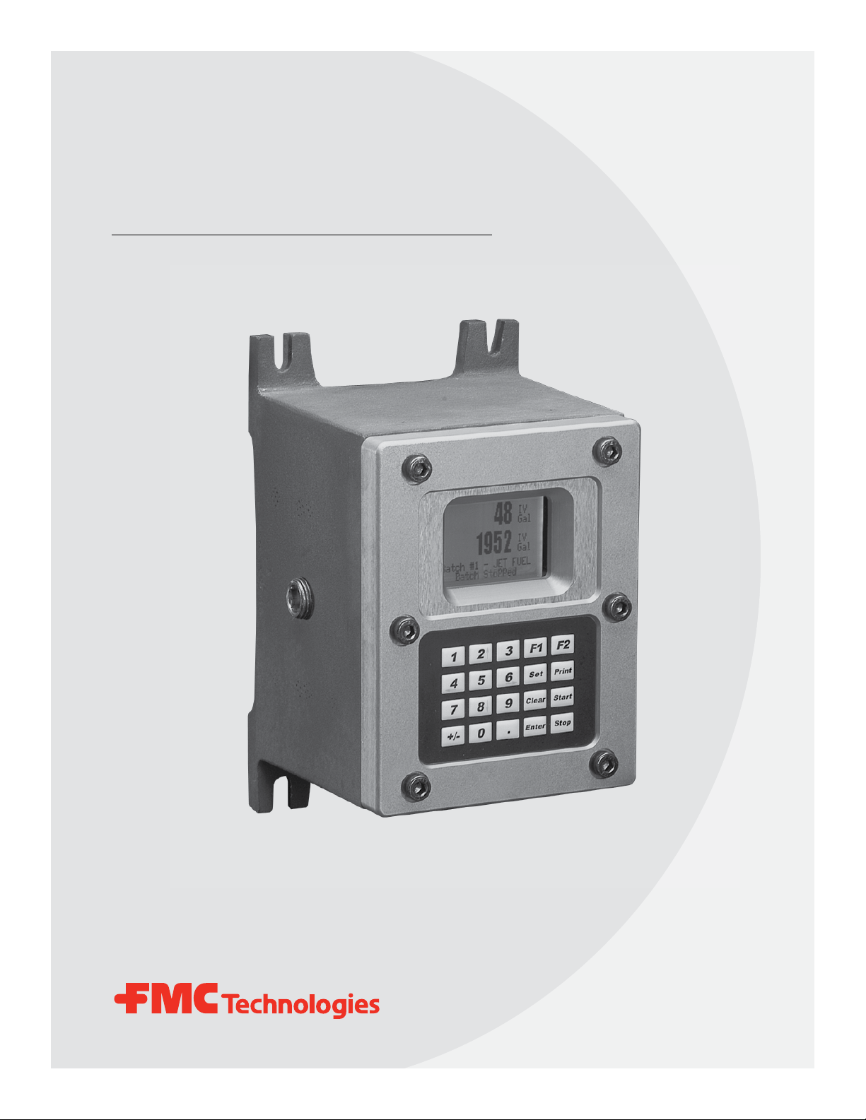
Electronic Preset Delivery System
Smith Meter®
microFlow.net Liquid
Modbus and Modbus/TCP Communications

Page 2 • MNFL003 ║ Issue/Rev. 0.1 (9/13)
Caution
The default or operating values used in this manual and in the program of the microFlow.net Liquid are for factory
testing only and should not be construed as default or operating values for your metering system. Each metering
system is unique and each program parameter must be reviewed and programmed for that specific metering system
application.
Disclaimer
FMC Technologies Measurement Solutions, Inc. hereby disclaims any and all responsibility for damages, including
but not limited to consequential damages, arising out of or related to the inputting of incorrect or improper program
or default values entered in connection with the microFlow.net Liquid.
Proprietary Notice
This document contains information that is proprietary to FMC Technologies Measurement Solutions, Inc. and is
available solely for customer information. The information herein shall not be duplicated, used, or disclosed without
prior permission of FMC Technologies Measurement Solutions, Inc.
FMC Technologies Measurement Solutions, Inc. will not be held responsible for loss of liquid or for damage of any
kind or from any cause to the person or property of others, or for loss or profit, or loss of use, or any other special,
incidental, or consequential damages caused by the use or misapplication of the contents stated herein.
Important
All information and technical specications in this documentation have been carefully checked and compiled by the
author. However, we cannot completely exclude the possibility of errors. FMC Technologies is always grateful to be
informed of any errors.
Smith Meter® is a registered trademark of FMC Technologies.
Customer Support
Contact Information:
Customer Service
FMC Technologies Measurement Solutions, Inc.
1602 Wagner Avenue
Erie, Pennsylvania 16510 USA
P: +1 814 898-5000
F: +1 814 899-8927
www.fmctechnologies.com

Issue/Rev. 0.1 (9/13) ║ MNFL003 • Page 3
Table of Contents
1 – Introduction........................................................................................................................................................................... 5
1.1 – Modbus/TCP ........................................................................................................................................................................ 5
1.2 – Floating Point Endian Control .............................................................................................................................................. 6
1.3 – Communications Control Selections.................................................................................................................................... 6
1.4 – Configuring the microFlow.net Liquid for Modbus Communications via Serial Port ............................................................ 6
1.5 – Configuring the microFlow.net Liquid for Modbus Communications via TCP/IP (Ethernet or SLIP) ................................... 7
2 – Implementing Remote Host Functionality.......................................................................................................................... 8
2.1 – Implementing Host Status Polling........................................................................................................................................ 8
2.2 – Implementing Host Control (Automation) Interface via Modbus .......................................................................................... 8
2.21 – Special Modbus Registers for Host Control....................................................................................................................... 8
2.22 – Host Command Result Status Register ............................................................................................................................. 8
2.23 – Program Mode Interface-Entering Program Mode via Modbus ......................................................................................... 9
2.24 – Program Mode Interface-Explicit Logout Command.......................................................................................................... 9
2.25 – Set Time/Date .................................................................................................................................................................. 10
2.26 – Alarm Clearing ................................................................................................................................................................. 10
2.27 – Other Host Clearable Flags (Program Change, Power Fail, Transaction/Batch Done, etc.) ........................................... 10
2.28 – Set Max Transaction Amount........................................................................................................................................... 10
2.29 – Allocate Recipes .............................................................................................................................................................. 10
2.30 – Batch Preset/Authorization Options..................................................................................................................................11
2.31 – Read Transaction Log ......................................................................................................................................................11
2.32 – Read Event Log ............................................................................................................................................................... 12
2.33 – Read Audit Log ................................................................................................................................................................ 12
3 – Modbus Register Reference.............................................................................................................................................. 13
4 – Appendix ............................................................................................................................................................................. 22
4.1 – Modbus Communications Primer ...................................................................................................................................... 22
4.11 – RTU Framing ................................................................................................................................................................... 22
4.12 – How Characters are Transmitted Serially ........................................................................................................................ 23
4.13 – Data Addresses in Modbus Messages ............................................................................................................................ 23
4.2 – Modbus Functions ............................................................................................................................................................. 23
4.3 – Master/Slave Communications .......................................................................................................................................... 24
4.4 – Contenes of the Data Field ................................................................................................................................................ 24
4.41 – Beginning Register .......................................................................................................................................................... 25
4.42 – Number of Requested Registers ..................................................................................................................................... 25
4.43 – Error Check (CRC16) ...................................................................................................................................................... 25
4.5 – Placing the CRC into the Message.................................................................................................................................... 25
4.51 – Field Contents in Modbus Messages .............................................................................................................................. 26
4.52 – Address............................................................................................................................................................................ 27
microFlow.net Liquid Modbus Communications Manual Table of Contents

Page 4 • MNFL003 ║ Issue/Rev. 0.1 (9/13)
4.6 – Query Responses .............................................................................................................................................................. 27
4.61 – Byte Count ....................................................................................................................................................................... 27
4.62 – Data Register................................................................................................................................................................... 27
4.7 – 01 Read Relay Status........................................................................................................................................................ 28
4.8 – 02 Read Input Status ......................................................................................................................................................... 29
4.9 – 03 Read Holdings Registers .............................................................................................................................................. 30
5.0 – 04 Read Input Registers .................................................................................................................................................... 31
5.1 – 05 Force Single Relay ....................................................................................................................................................... 31
5.2 – 06 Preset Single Register .................................................................................................................................................. 32
5.3 – 15 (0F Hex) Force Multiple Relays .................................................................................................................................... 33
5.4 – 16 (10 Hex) Preset Multiple Registers ............................................................................................................................... 34
5.5 – Exception Responses ........................................................................................................................................................ 35
5.6 – How to access 64-bit information using Modbus when Modbus will only read 32-bit information ..................................... 36
6 – Related Publications .......................................................................................................................................................... 37
microFlow.net Liquid Modbus Communications Manual Table of Contents

Issue/Rev. 0.1 (9/13) ║ MNFL003 • Page 5
1 – Introduction
The Modbus protocol was developed by Modicon, Inc. to be a concise method of
transferring data to/from programmable logic controllers (PLCs). It has become a
de-facto standard in many areas of industrial automation where supervisry control
or remote data collection is required. In a Modbus system, a host (master) commu-
nicates with one or multiple field devices (slaves). The microFlow.net Liquid acts as
a slave device only; an external host must act as the master to query or control the
microFlow.net Liquid. Each microFlow.net Liquid must have a unique communication
address in the range of 1 to 99. It is recommended that communications ports 2 or 3
on the microFlow.net Liquid be used for Modbus communications. Host messages
to address 0 (the Modbus broadcast address) are not currently supported (are
ignored) by the mcroFlow.net Liquid. For more information regarding Modbus commu-
nications specifics, refer to the Modbus Communications primer inthe Appendix.
1.1 Modbus/TCP
Modbus/TCP is a standard that defines a TCP/IP based version of the Modbus protocol
for use over communications links such as Ethernet, etc.
All requests are sent via TCP on registered port 502.
Requests are normally sent in half-duplex fashion on a given connection. That is, there is
no benefit in sending additional requests ona single connection while a response is
outstanding. Devices which wish to obtain high peak transfer rates are instead
encouraged to establish multiple TCP connections to the same target, however some
existing client devices are known to attempt to ‘pipeline’ requests. Design techniques
which allow a server to accommodate this behavior are described in Appendix A.
The Modbus ‘slave address’ field is replaced by a single byte ‘Unit Identifier’ which may
be used to communicate via devices such as bridges and gateways which use a single
IP address to support multiple independent end units.
The original Modbus protocol request and response are prefixed by six bytes in Modbus/
TCP as follows:
byte 0: transaction identifier - copied by server - usually 0
byte 1: transaction identifier - copied by server - usually 0
byte 2: protocol identifier = 0
byte 3: protocol identifier = 0
byte 4: length field (upper byte) = 0 (since all messages are smaller than 256)
byte 5: length field (lower byte) = number of bytes following
byte 6: unit identifier (previously ‘slave address’)
byte 7: Modbus function code
byte 8 and up: data as needed
So an example transaction ‘read 1 register at offset 4 from UI 9’ returning a value of 5
would be:
request: 00 00 00 00 00 06 09 03 00 04 00 01
response: 00 00 00 00 00 05 09 03 02 00 05
Designers familiar with Modbus should note that the ‘CRC-16’ or ‘LRC’ check fields are
NOT needed in Modbus/TCP. The TCP/IP and link layer (eg. Ethernet) checksum
mechanisms instead are used to verify accurate delivery of the packet.
For detailed specifications on the Modbus protocol refer to the following website:
www.modbus.org.
microFlow.net Liquid Modbus Communications Manual Introduction

Page 6 • MNFL003 ║ Issue/Rev. 0.1 (9/13)
microFlow.net Liquid Modbus Communications Manual Introduction
1.2 Floating Point Endian Control
Floating-point numbers are not defined in the Modbus specification; there are nearly as
many variations of how it is supported as there are vendors. Most often, Modbus registers
are combined sequentially to make up an IEEE single precision or double precision floating
point number; this is the case in the microFlow.net Liquid. Two registers are needed for
single precision and four fordouble precision numbers. There are, however, several ways to
map floating point values to Modbus registers. To assure compatibility with off-the-shelf
drivers, three popular variations of byte ordering for floating point numbers are supported
(see system program code 727).
1.3 Communications Control Selections
This program code defines the level of control the associated communications port commands.
Poll and Program, and Host Control are valid with host communications options. XON/
XOFF is valid with printer options. Selections are as follows:
None – No communications control on this port.
Poll & Program – For use with demonstration/microMate ports. Allows full program
access but does not affect transaction control (acts like a standalone unit).
Host Control – Full programming and prompting control. plus transaction control
(requiring authorization from host). Allows use of AU or AP (Authorize, Authorize to
Preset) or SB (Set Batch) to enter the preset remotely.
Xon/Xoff – For printer ports only. Xon/Xoff flow control.
PTB-FX – For printer ports only. Security level designed to support PTB compliant
printers.
PTB-LQ – For printer ports only. Security level designed to support PTB compliant
printers.
Critical: Comm port not configured for host communications.
Critical: Comm port not configured for printer.
Note: No entry if corresponding function = Not Used.
Help: Select the degree of control for this communications port.
1.4 Configuring the microFlow.net Liquid for Modbus Communications Via
Serial Port
• Press <Enter> at the Ready screen to access the Main Menu
• From the Main Menu, select Program Mode Menu and press <Enter>
• Enter the Access Code when prompted and press <Enter>
• From the Program Mode, select Comm Directory and press <Enter>
• Select Comm Port Config and press <Enter>
• From the Comm Port Config menu, select the desired port
• From the chosen communications port, set up the following items:
Baud Rate – the rate at which the Modbus device is sending data.
Data Parity – typical or standard setting is 8/None.
Control – can be Host Control, but standard is Poll and Program due to
access being granted at the microFlow.net Liquid to start/stop batches (refer
to Comm. Control Settings in previous section).
Timeout – dependent on Modbus host polling rate and number of slave
devices in the loop.

Issue/Rev. 0.1 (9/13) ║ MNFL003 • Page 7
microFlow.net Liquid Modbus Communications Manual Introduction
Mode – dependent on EIA 232/EIA 485 wiring configuration. Must match
the master device.
• Return to the Main Menu by pressing the <Clear> key.
1.5 Configuring the microFlow.net Liquid for Modbus Communications via
TCP/IP (Ethernet or SLIP)
• Press <Enter> at the Ready screen to access the Main Menu
• From the Main Menu, select Program Mode Menu and press <Enter>
• Enter the Access Code when prompted and press <Enter>
• From the Program Mode menu, select Comm. Directory and Press <Enter>
• Select Host Interface and press <Enter>
• From the Host interface Menu set the following items:
Host Interface
IP Address: 192.168.0.1
Net mask: 255.255.255.0
Gateway: 192.168.0.10
Ethernet Control: Poll and Program
-->Comm Link: Level 3
• Return to the Main Menu using the <Clear> key
To access Modbus/TCP on microFlow.net Liquid – connect to the standard Modbus/
TCP port 502 via the Ethernet port or a serial port configured for SLIP.

Page 8 • MNFL003 ║ Issue/Rev. 0.1 (9/13)
2 – Implementing Remote Host Functionality
2.1 Implementing Host Status Polling
To implement routine polling loops, the following coils should be periodically read. These
coils represent the critical states that a host should monitor.
Coil State
0 In Program Mode – Set when Program mode is accessed, via communications
or keypad
1 Checking Entries – Active when exiting Program mode, during the validation
phase
2 Program Mode Value Changed1– Active after exiting Program mode when
changes made
3 Power-fail Occurred1– Set on powerup
4 Printing in Progress – Set when printing a report (if a port is configured as a
Printer)
Coil State
264 Alarm Active2 – Active when an alarm condition is present
266 Product Flowing – Active when the flow rate is nonzero
267 Permissive Not Met – Active when the transaction is in progress but a
permissive input is de-asserted
1 – These flags are clearable by writing a 0 to the coil using Modbus Function 5 or 15.
2 – Writing a zero to the Alarm Active coil will effectively clear all active alarms (assuming the condition no
longer exists).
2.2 Implementing Host Control (Automation) Interface via Modbus
2.21 Special Modbus Registers for Host Control
Certain registers are “trigger” registers that invoke a host automation command such as
a prompting function or a remote authorization function. These registers are listed here.
Note that some of these “trigger” registers require other registers have valid argument
values prior to invoking the command trigger.
Registers that are “trigger” registers will be designated with the superscript symbol † in
the appendix. Registers that act as arguments for a trigger register are in italics.
2.22 Host Command Result Status Register
For each write to a trigger register that implements a host command, the result of the
operation will be left in the Host Result register (Function 4, register 3590). If the com-
mand was executed successfully the value in this register will be 254. Otherwise the
value in the register will be set to one of the following error codes indicating the opera-
tion was not completed for the reason described below:
01 In Program Mode
02 Released
03 Value Rejected
04 Flow Active
05 No Transaction Ever Done
06 Operation Not Allowed
07 Wrong Control Mode
08 Transaction In Progress
microFlow.net Liquid Modbus Communications Manual Implementing Remote Host Functionality

Issue/Rev. 0.1 (9/13) ║ MNFL003 • Page 9
microFlow.net Liquid Modbus Communications Manual Implementing Remote Host Functionality
09 Alarm Condition
10 Storage Full
11 Operation Out Of Sequence
12 Power Failed During Transaction
13 Already Authorized
14 Program Code Not Used
15 Display/Keypad In Remote Mode
16 Ticket Not In Printer
17 No Keypad Data Pending
18 No Transaction In Progress
19 Option Not Installed/Enabled
20 Start After Stop Delay In Effect
21 Permissive Not Met
22 Print Request Pending
23 No Meter Enabled
24 Must Be In Program Mode
25 Ticket Alarm During Transaction
26 Volume Type Not Available
27 Exactly One Recipe Must Be Enabled
28 Batch Limit Reached
29 Checking Entries
30 Product/Recipe/Additive Not Assigned To This Arm
31 Operation Conflicts With Arm Configuration
32 No Key Ever Pressed
33 Active Arm Limit Already Met
34 Transaction Not Standby
35 Swing Arm Out Of Position
36 Card-In Required
37 Data Not Available
38 Too Many Shared Additives
39 No Current Batch On This Arm
40 Must Use Minicomputer Protocol For This Operation
91 Communications Buffer Allocation Error
92 Keypad Locked
93 Data Recall Error
94 Not In Program Mode
95 Security Access Not Available
96 Internal Error
2.23 Program Mode Interface – Entering Program Mode via Modbus
Entry to Program mode via Modbus is done by simply writing a value to a configuration
register in the map (assuming all security requirements are met). Each write to the con-
figuration restarts the auto-logout timer. If three seconds transpire with no additional
updates (writes), it is assumed by the microFlow.net Liquid that the host has completed
the Program Mode session and the changes will be accepted and used (if all were valid).
See the Operator Reference manual for detailed descriptions of the various Program
Codes available for configuration of the microFlow.net Liquid.
2.24 Program Mode Interface – Explicit Logout Command
Register: 40577 (Function 6/16 – Write Holding Register) – word data
If it is not desired to wait for the three second period to expire, it is possible to force
the unit to exit program mode immediately by writing to the above register. If the value
1 is written, the preceding changes will be accepted and used. If the value 2 is written,
any changes made will be abandoned and the original values prior to entry into Program
mode by the Modbus host will continue to be used.
Note: this immediate logout functionality is also assumed implicitly when host commands like Allocate Recipes
or Set Batch are issued when in Program mode via Modbus.

Page 10 • MNFL003 ║ Issue/Rev. 0.1 (9/13)
microFlow.net Liquid Modbus Communications Manual Implementing Remote Host Functionality
2.25 Set Time/Date
To set the date and time via Modbus, write the following holding registers (Function 3):
7688 (30344) Time Set - Year, 4 digit
7689 (30345) Time Set - Month
768A (30346) Time Set - Day
768B (30347) Time Set - Hour
768C (30348) Time Set - Minute
768D (30349) Time Set - Seconds
768E (30350)† Time Set (0=MIL,1=AM,2=PM)
2.26 Alarm Clearing
Force the Alarm Status coil Off (Write a 0 to coil 264 using Modbus Function 5/15) to
clear all active alarms.
2.27 Other Host Clearable Flags (Program Change, Power Fail, Transaction/
Batch Done, etc.)
Force the status flag Off (Write a 0 to coil using Modbus Function 5/15) to clear the flag.
Coil # Status Flag Cleared on Write of 0
2 Program Mode Value Changed
3 Power-fail Occurred
259 Batch Done
260 Transaction Done
2.28 Set Max Transaction Amount
Write the maximum total amount allowed for the transaction when host authorization of
type AU/AP will be issued (i.e. the operator/driver will determine batch sizes):
9F00-9F01 (40704-40705)† TA - Set Transaction Maximum Amount (unsigned long
integer)
Range is 0-99,999
Note: The Communications Port Control must be set to Host Control for the Set Max Transaction Amount
Function.
2.29 Allocate Recipes
9F06-9F07 (40710-40711)† AB - Recipe Mask (unsigned long integer)
The value written to this register is determined via a bitmap. Each bit represents a recipe,
with the bit value being determined by the formula 2(r-1) where r is the recipe number
(1-12). Hence, the least significant bit (20 or 1) represents Recipe 1.
Value Representation
1 Recipe 1
2 Recipe 2
3 Recipes 1 and 2
4 Recipe 3
5 Recipes 1 and 3
6 Recipes 2 and 3
7 Recipes 1, 2 and 3
etc...

Issue/Rev. 0.1 (9/13) ║ MNFL003 • Page 11
Bit# Bit 31 . . . Bit 4 Bit 3 Bit 2 Bit 1 Bit 0
Value 16 8 4 2 1
Recipe N/A R5 R4 R3 R2 R1
Example: If recipes 3 and 5 are the only valid recipes for this load, the value to write to
this register prior to authorization would be:
2
(5-1) + 2(3-1)
= 2
4 + 22
= 16 + 4
= 20
Range is 0-4095
Note: The Communications Port Control must be set to Host Control for the Allocated Blend Recipes Function.
2.30 Batch Preset/Authorization Options
The batch can be reset by writing to register 40578. The value written selects the recipe
for the new batch as follows:
0 - Reset batch, new batch will be the same recipe as current batch
1 - Reset batch, new batch will be recipe 1
2 - Reset batch, new batch will be recipe 2
3 - Reset batch, new batch will be recipe 3
4 - Reset batch, new batch will be recipe 4
2.31 Read Transaction Log
The transaction data is read from the same Modbus locations for both current and his-
torical transactions. Hence, historical transaction data should only be requested during
idle periods. Also, to read current data the Transaction Select register MUST BE SET
TO 0. After reading historic transaction log data, be sure to set the host transaction
select register back to 0 to be able to read current run data.
To retrieve transaction data:
Write host transaction select register - 0=current, 1 or greater = number back in storage
Function 6, register 40587† (unsigned integer)
Read Modbus host command result to assure the retrieval was successful
Function 4, register 3594 (254 on success, an error code from 1-99 otherwise)
Read the transaction data areas as you would for a current transaction
Example - read transaction header info – end time text, start time text
Function 4, registers 2384-2399 (text)
Function 4, registers 2400-2415 (text)
Example 2 - read unsigned character batch run data – recipe number
Function 4, register 5632 (unsigned integer)
microFlow.net Liquid Modbus Communications Manual Implementing Remote Host Functionality

Page 12 • MNFL003 ║ Issue/Rev. 0.1 (9/13)
2.32 Read Event Log
To read historical events from the event log, the following steps are used. The most
recent event log entry’s sequence number is available via Function 4, registers 1792-
1793 (unsigned long integer).
To read an entry:
• Write desired event’s sequence number to request register (Function 16; registers
30464-30465)†
• Read text for event from Event/Audit Log Text registers (Function 4, registers
16-63, Text)
If an error occurs (such as invalid seq #, etc.) the Host Result Register will be set to
a value other than 254 indicating the error. On success, the Host Result Register will
contain the value 254.
2.33 Read Audit Log
Reading from the Audit Log uses the same procedure as reading from the Event Log.
Replace the register numbers for the most recent entry and the request with the Audit Log
equivalents; the entry itself is read from the same location for both the Event and Audit
logs: The most recent Audit Log entry’s sequence number can be read via Function 4,
registers 1794-1795 (unsigned long integer).
To read an entry:
• Write desired entry sequence number to request register (Function 16, registers
30466-30467)†
• Read text for event from Event/Audit Log Text registers (Function 4, registers
16-63, Text)
If an error occurs (such as invalid seq #, etc.) the Host Result Register will be set to
a value other than 254 indicating the error. On success, the Host Result Register will
contain the value 254.
microFlow.net Liquid Modbus Communications Manual Implementing Remote Host Functionality

Issue/Rev. 0.1 (9/13) ║ MNFL003 • Page 13
3 – Modbus Register Reference
------------------------------------------------------------------------
INPUT (STATUS) COILS - Function 2
-----------------------------------------------------------------------
Dec. Hex. Description
Directory: SYS_RUN_DATA
Data Type: BOOLEAN
Start Address: 0
0 (0000) In Program Mode
1 (0001) Checking Entries
2 (0002) Program Mode Value Changed
3 (0003) Power Fail Occurred
4 (0004) Printing In Progress
5 (0005) Card Status
6 (0006) Card Valid
7 (0007) Printer Standby
Directory: TRAN_RUN_DATA
Data Type: BOOLEAN
Start Address: 264
264 (0108) Alarm Active
266 (010A) Product Flowing
267 (010B) Permissive Not Met
Directory: DIG_RUN_DATA
Data Type: BOOLEAN
Start Address: 1536
1536 (0600) Current Digital I/O State
Directory: SYSTEM_ALARMS
Data Type: BOOLEAN
Start Address: 2560
2560 (0A00) DA: ROM Bad
2561 (0A01) DA: RAM Bad
2562 (0A02) DA: Flash Memory Error
2563 (0A03) DA: RAM Corrupt on Power-up
2564 (0A04) DA: Flash Corrupt on Power-up
2565 (0A05) DA: Watchdog Alarm
2566 (0A06) DA: Program Error
2567 (0A07) DA: Passcodes Reset
2568 (0A08) PA: Power Fail Alarm
2569 (0A09) U1: User Alarm 1
2570 (0A0A) U2: User Alarm 2
2571 (0A0B) U3: User Alarm 3
2572 (0A0C) U4: User Alarm 4
2573 (0A0D) U5: User Alarm 5
2574 (0A0E) CM: Communications Alarm
2575 (0A0F) ZF: Zero Flow Alarm
2576 (0A10) PS: Pulse Security Alarm
2577 (0A11) VF: Valve Fault Alarm
2578 (0A12) BP: Back Pressure Alarm
2579 (0A13) TP: Temperature Probe Alarm
2580 (0A14) DR: Density Transducer Failure
2581 (0A15) PR: Pressure Transducer Fail
2582 (0A16) HF: High Flow Alarm
2583 (0A17) HT: High Temperature Alarm
2584 (0A18) HD: High Density Alarm
2585 (0A19) HP: High Pressure Alarm
2586 (0A1A) LF: Low Flow ALarm
2587 (0A1B) LT: Low Temperature Alarm
2588 (0A1C) LD: Low Density Alarm
2589 (0A1D) LP: Low Pressure Alarm
2590 (0A1E) MF: Mass Meter Comm Fail
2591 (0A1F) MO: Mass Meter Overdrive
2592 (0A20) MT: Mass Meter Tube Fail
2593 (0A21) PP: PTB Printer Failure
2594 (0A22) SP: Shared Printer Failure
2595 (0A23) SA: Sampler Error
2596 (0A24) HB: High BS&W
2597 (0A25) UC: Ultrasonic Comm Fail
2598 (0A26) UM: Ultrasonic Meter Fail
Directory: INJECTOR_ALARMS
Data Type: BOOLEAN
Start Address: 3584***
3584 (0E00) AC: Additive Communications
3585 (0E01) CR: Injector Command Rejected
3586 (0E02) FA: Additive Feedback Alarm
3587 (0E03) GA: Additive Injector Error
3588 (0E04) KA: Low Additive Volume
3589 (0E05) MA: Excess Additive Pulses
3590 (0E06) NA: No Additive Pulses Alarm
3591 (0E07) OR: Overspeed Injector
3592 (0E08) RA: Additive Frequency Alarm
3593 (0E09) UA: Add Unauthorize Failed
*** ADD 32 to get to Injector #2, add 64 to get to Injector
#3, add 96 to get to Injector #4
-----------------------------------------------------------------------
OUTPUT COILS - Function 1/5/15
-----------------------------------------------------------------------
Directory: DIGITAL_CMDS
Data Type: BOOLEAN
Start Address: 4096
4096 (1000) Set Digital Output 1 Value
4097 (1001) Set Digital Output 2 Value
4098 (1002) Set Digital Output 3 Value
4099 (1003) Set Digital Output 4 Value
4100 (1004) Set Digital Output 5 Value
4101 (1005) Set Digital Output 6 Value
microFlow.net Liquid Modbus Communications Manual Modbus Register Reference

Page 14 • MNFL003 ║ Issue/Rev. 0.1 (9/13)
Directory: SYSTEM_DIR
Data Type: FLOATING POINT
Start Address: 6912
6912 (1B00) 102 Pulse Out 1 Pulses/Amount
6914 (1B02) 104 Pulse Out 1 Max Frequency
6916 (1B04) 402 Reference Temperature
6918 (1B06) 814 Inject to Totals Convert
Directory: SYSTEM_DIR
Data Type: UNSIGNED_CHAR
Start Address: 7680
7680 (1E00) 101 Pulse Output Function
7681 (1E01) 103 Pulse Output Units
7682 (1E02) 111 Flow Rate Time
7683 (1E03) 113 Volume Units
7684 (1E04) 115 Mass Units
7685 (1E05) 122 Run Display Options
7686 (1E06) 123 Display Resolution
7687 (1E07) 124 Decimal/Comma Select
7688 (1E08) 125 Default/Translated Literals
7689 (1E09) 131 Dynamic Display Timeout
7690 (1E0A) 132 Auto Reset Time
7691 (1E0B) 141 Batch Reset Enable
7692 (1E0C) 302 Pulse In Type
7693 (1E0D) 303 Channel Select
7694 (1E0E) 401 Temperature Units
7695 (1E0F) 411 Density Units
7696 (1E10) 501 Pressure Units
7697 (1E11) 601 Driver Alarm Clearing
7698 (1E12) 602 Powerfail Alarm
7699 (1E13) 725 Comm Link Programming
7700 (1E14) 811 Add Injector Pacing Units
7701 (1E15) 821 Add Injector Stop Option
7702 (1E16) 724 Ethernet Host Control
7703 (1E17) 727 Modbus Endian Select
7704 (1E18) 735 User Text Archived
7705 (1E19) 142 Sampler Type
7706 (1E1A) 143 Sampler Pace
7707 (1E1B) 144 Sampler Pulse Width
7708 (1E1C) 145 Sampler Disable
------------------------------------------------------------------------
Program Configuration, etc. - HOLDING REGISTERS
- Function 3,6,16 table:
-----------------------------------------------------------
Dec. Hex. Parameter # and Description
Directory: DIGITAL_DIR
Data Type: UNSIGNED_CHAR
Start Address: 3584
3584 (0E00) 201 Input 1 (DC) Function Select
3585 (0E01) 202 Input 2 (DC) Function Select
3586 (0E02) 203 Input 3 (DC) Function Select
3587 (0E03) 301 Output 1 (DC) Function Select
3588 (0E04) 302 Output 2 (DC) Function Select
3589 (0E05) 303 Output 3 (AC) Function Select
3590 (0E06) 304 Output 4 (AC) Function Select
3591 (0E07) 305 Output 5 (AC) Function Select
3592 (0E08) 306 Output 6 (AC) Function Select
Directory: ANALOG_DIR
Data Type: FLOATING POINT
Start Address: 4864
4864 (1300) 402 Analog I/O 1 RTD Offset
4866 (1302) 412 Analog I/O 2 (4-20ma) Low
Value
4868 (1304) 413 Analog I/O 2 (4-20ma) High
Value
Directory: ANALOG_DIR
Data Type: UNSIGNED_CHAR
Start Address: 5632
5632 (1600) 401 RTD Function
5633 (1601) 411 4-20 ma Function
Directory: SYSTEM_DIR
Data Type: TEXT
Start Address: 6144
6144 (1800) 101 Date{O}
6160 (1810) 102 Time{O}
6176 (1820) 112 Flow Rate Descriptor
6192 (1830) 114 Volume Descriptor
6208 (1840) 116 Mass Descriptor
6224 (1850) 691 User Alarm 1 Message
6240 (1860) 692 User Alarm 2 Message
6256 (1870) 693 User Alarm 3 Message
6272 (1880) 694 User Alarm 4 Message
6288 (1890) 695 User Alarm 5 Message
6304 (18A0) 812 Additive Units Descriptor
6320 (18B0) 813 Additive Totals Units
microFlow.net Liquid Modbus Communications Manual Modbus Register Reference

Issue/Rev. 0.1 (9/13) ║ MNFL003 • Page 15
Directory: SYSTEM_DIR
Data Type: UNSIGNED_LONG
Start Address: 7936
7936 (1F00) 721 IP Address
7938 (1F02) 722 Netmask
7940 (1F04) 723 Gateway
7942 (1F06) 334 Ultrasonic Address
Directory: SECURITY_DIR
Data Type: UNSIGNED_INTEGER
Start Address: 9856
9856 (2680) 161 Level 1 Access Code
9857 (2681) 162 Level 2 Access Code
9858 (2682) 163 Level 3 Access Code
9859 (2683) 164 Level for Security Input
9860 (2684) 165 Level for Diagnostics Dir.
Directory: PROMPT_DIR
Data Type: TEXT
Start Address: 10240
10240 (2800) 763 Prompt 1 Message
10256 (2810) 766 Prompt 2 Message
10272 (2820) 769 Prompt 3 Message
10288 (2830) 772 Prompt 4 Message
10304 (2840) 775 Prompt 5 Message
Directory: PROMPT_DIR
Data Type: UNSIGNED_CHAR
Start Address: 11776
11776 (2E00) 761 Prompts Used
11777 (2E01) 762 Prompt Timeout
11778 (2E02) 764 Prompt 1 Input Type
11779 (2E03) 765 Prompt 1 Length
11780 (2E04) 767 Prompt 2 Input Type
11781 (2E05) 768 Prompt 2 Length
11782 (2E06) 770 Prompt 3 Input Type
11783 (2E07) 771 Prompt 3 Length
11784 (2E08) 773 Prompt 4 Input Type
11785 (2E09) 774 Prompt 4 Length
11786 (2E0A) 776 Prompt 5 Input Type
11787 (2E0B) 777 Prompt 5 Length
Directory: ALARM_DIR
Data Type: UNSIGNED_CHAR
Start Address: 13824
13824 (3600) 611 Communications Alarm
13825 (3601) 621 High Flow Alarm
13826 (3602) 622 Low Flow Alarm
13827 (3603) 623 Back Pressure Alarm
13828 (3604) 624 Valve Fault Alarm
13829 (3605) 626 Zero Flow Alarm
13830 (3606) 635 High Temperature Alarm
13831 (3607) 636 Low Temperature Alarm
13832 (3608) 637 Temp Transducer Alarm
13833 (3609) 638 High Density Alarm
13834 (360A) 639 Low Density Alarm
13835 (360B) 640 Density Transducer Alarm
13836 (360C) 641 High Pressure Alarm
13837 (360D) 642 Low Pressure Alarm
13838 (360E) 643 Pres Transducer Alarm
13839 (360F) 651 Pulse Security Alarm
13840 (3610) 652 Mass Mtr Comm Alarm
13841 (3611) 653 Mass Mtr Overdrive Alarm
13842 (3612) 654 Mass Mtr Tube Alarm
13843 (3613) 665 Additive Feedback Error
13844 (3614) 666 Additive Comm Failure
13845 (3615) 667 Low Additive Alarm
13846 (3616) 668 Excess Additive Pulses
13847 (3617) 669 No Additive Pulses Alarm
13848 (3618) 670 Additive Frequency Alarm
13849 (3619) 671 Add Unauthorize Fail
13850 (361A) 672 Add Inj Error
13851 (361B) 673 OverRev Metered Inj
13852 (361C) 674 Injector Command Rejected
13853 (361D) 612 PTB Printer Failure
13854 (361E) 613 Shared Printer Failure
13855 (361F) 614 Sampler Failure
13856 (3620) 644 High BS&W Alarm
13857 (3621) 645 BS&W Transducer Alarm
13858 (3622) 655 Ultrasonic Comm Alarm
13859 (3623) 656 Ultrasonic Meter Alarm
Directory: USER_ALARM_DIR
Data Type: UNSIGNED_CHAR
Start Address: 15872
15872 (3E00) 681 User Alarm 1
15873 (3E01) 682 User Alarm 2
15874 (3E02) 683 User Alarm 3
15875 (3E03) 684 User Alarm 4
15876 (3E04) 685 User Alarm 5
Directory: COMM_PORT_DIR
Data Type: UNSIGNED_CHAR
Start Address: 17920
17920 (4600) 701 Comm 1 Function
17921 (4601) 707 Comm 2 Function
17922 (4602) 713 Comm 3 Function
17923 (4603) 702 Comm 1 Baud Rate
17924 (4604) 708 Comm 2 Baud Rate
17925 (4605) 714 Comm 3 Baud Rate
17926 (4606) 703 Comm 1 Data/Parity
17927 (4607) 709 Comm 2 Data/Parity
17928 (4608) 715 Comm 3 Data/Parity
17929 (4609) 704 Comm 1 Control
17930 (460A) 710 Comm 2 Control
17931 (460B) 716 Comm 3 Control
17932 (460C) 706 Comm 1 Mode
microFlow.net Liquid Modbus Communications Manual Modbus Register Reference

Page 16 • MNFL003 ║ Issue/Rev. 0.1 (9/13)
17933 (460D) 712 Comm 2 Mode
17934 (460E) 718 Comm 3 Mode
Directory: COMM_PORT_DIR
Data Type: UNSIGNED_INTEGER
Start Address: 18048
18048 (4680) 705 Comm 1 Timeout
18049 (4681) 711 Comm 2 Timeout
18050 (4682) 717 Comm 3 Timeout
18051 (4683) 726 Ethernet Host Timeout
Directory: INJ_DIR
Data Type: FLOAT
Start Address: 19200
19200 (4B00) 831 Metered Inj K Factor
19202 (4B02) 832 Metered Inj Meter Fac
19204 (4B04) 833 Metered Inj High Tol
19206 (4B06) 834 Metered Inj Low Tol
Directory: INJ_DIR
Data Type: UNSIGNED_CHAR
Start Address: 19968
19968 (4E00) 801 Additive Injector 1 Type
19969 (4E01) 802 Additive Injector 2 Type
19970 (4E02) 803 Additive Injector 3 Type
19971 (4E03) 804 Additive Injector 4 Type
19972 (4E04) 835 Metered Inj Max Tol Err
Directory: INJ_DIR
Data Type: UNSIGNED_INTEGER
Start Address: 20096
20096 (4E80) 841 Add Injector 1 Address
20097 (4E81) 842 Add Injector 2 Address
20098 (4E82) 843 Add Injector 3 Address
20099 (4E83) 844 Add Injector 4 Address
Directory: LOAD_ARM_DIR
Data Type: TEXT
Start Address: 20480
20480 (5000) 121 Position ID
20496 (5010) 152 Permissive 1 Message
20512 (5020) 154 Permissive 2 Message
20528 (5030) 733 Report Print Time
Directory: LOAD_ARM_DIR
Data Type: FLOAT
Start Address: 21248
21248 (5300) 202 Low Flow Start Rate
21250 (5302) 203 Low Flow Start Amount
21252 (5304) 204 Low Flow Start % of Batch
21254 (5306) 223 Overrun Alarm Limit
Directory: LOAD_ARM_DIR
Data Type: UNSIGNED_CHAR
Start Address: 22016
22016 (5600) 151 Permissive 1 Sense
22017 (5601) 153 Permissive 2 Sense
22018 (5602) 231 Zero Flow Timer
22019 (5603) 232 Valve Fault Timeout
22020 (5604) 731 Report Select
22021 (5605) 732 Report Total Resolution
22022 (5606) 736 Batch Reset on Report
Directory: LOAD_ARM_DIR
Data Type: UNSIGNED_INTEGER
Start Address: 22144
22144 (5680) 734 Report Interval
Directory: METER_DIR
Data Type: FLOATING POINT
Start Address: 23296
23296 (5B00) 306 DP Flow Rate Cutoff
23298 (5B02) 363 SMASS Coefficient Ka
23300 (5B04) 364 SMASS Coefficient Kb
23302 (5B06) 365 SMASS Coefficient Kc
Directory: METER_DIR
Data Type: DOUBLE
Start Address: 23552
23552 (5C00) 301 K Factor
Directory: METER_DIR
Data Type: UNSIGNED_CHAR
Start Address: 24064
24064 (5E00) 201 Valve Type
24065 (5E01) 305 Dual Pulse Error Reset
24066 (5E02) 307 Pulse Security Alarm Amount
24067 (5E03) 308 Pulse Period Sample Count
24068 (5E04) 361 Mass Meter Type
24069 (5E05) 367 Mass Meter Pulse Multiplier
24070 (5E06) 368 Mass Meter Low Flow Cutoff
24071 (5E07) 369 Mass Meter Tube Material
24072 (5E08) 370 Mass Meter Model
24073 (5E09) 309 Pulse Multiplier
24074 (5E0A) 331 Ultrasonic Meter Type
24075 (5E0B) 332 Share Temp. w/Meter
24076 (5E0C) 333 Share Press. w/Meter
microFlow.net Liquid Modbus Communications Manual Modbus Register Reference

Issue/Rev. 0.1 (9/13) ║ MNFL003 • Page 17
Directory: METER_DIR
Data Type: UNSIGNED_INTEGER
Start Address: 24192
24192 (5E80) 304 Dual Pulse Error Count
24193 (5E81) 366 SMASS Density Factor
Directory: METER_DIR
Data Type: UNSIGNED_LONG
Start Address: 24320
24320 (5F00) 362 Mass Meter Sequence Number
Directory: PRODUCT_DIR
Data Type: FLOAT
Start Address: 25344
25344 (6300) 202 Minimum Flow Rate
25346 (6302) 203 High Flow Rate
25348 (6304) 204 Flow Tolerance %
25350 (6306) 210 Flow Tolerance Rate
25352 (6308) 221 Excess High Flow Amount
25354 (630A) 222 Low Flow Alarm Limit
25356 (630C) 341 Meter Factor 1
25358 (630E) 342 Flow Rate 1
25360 (6310) 343 Meter Factor 2
25362 (6312) 344 Flow Rate 2
25364 (6314) 345 Meter Factor 3
25366 (6316) 346 Flow Rate 3
25368 (6318) 347 Meter Factor 4
25370 (631A) 348 Flow Rate 4
25372 (631C) 349 Master Meter Factor
25374 (631E) 350 Linear Factor Deviation
25376 (6320) 352 Mtr Factor % Change Per Degree
25378 (6322) 353 Mtr Factor Variation Ref Temp
25380 (6324) 403 Maintenance Temperature
25382 (6326) 404 High Temperature Alarm
25384 (6328) 405 Low Temperature Alarm
25386 (632A) 413 Reference Density
25388 (632C) 414 High Density Alarm
25390 (632E) 415 Low Density Alarm
25392 (6330) 502 Maintenance Pressure
25394 (6332) 503 Pressure Coefficient
25396 (6334) 504 High Pressure Alarm Limit
25398 (6336) 505 Low Pressure Alarm Limit
25400 (6338) 512 BP Percent Reduction
25402 (633A) 513 Min BP Flow Rate
25404 (633C) 515 Differential Pressure
25406 (633E) 516 BP Flow Recovery Pressure
25408 (6340) 522 Vapor Pressure 1
25410 (6342) 523 Vapor Press Temp 1
25412 (6344) 524 Vapor Pressure 2
25414 (6346) 525 Vapor Press Temp 2
25416 (6348) 526 Vapor Pressure 3
25418 (634A) 527 Vapor Press Temp 3
25420 (634C) 321 Maintenance BS&W
25422 (634E) 322 BS&W Hi Alarm Limit
Directory: PRODUCT_DIR
Data Type: UNSIGNED_CHAR
Start Address: 26112
26112 (6600) 351 Meter Factor Variation Select
26113 (6601) 412 API Table
26114 (6602) 511 Min BP Flow Timer
26115 (6603) 514 BP Flow Recovery Timer
26116 (6604) 521 Vapor Pressure Calc Method
Directory: RECIPE_DIR
Data Type: TEXT
Start Address: 26624
26624 (6800) 002 Recipe Name
Directory: RECIPE_DIR
Data Type: FLOATING POINT
Start Address: 27392
27392 (6B00) 011 Add Inj 1 Amount/Cycle
27394 (6B02) 013 Add Inj 2 Amount/Cycle
27396 (6B04) 015 Add Inj 3 Amount/Cycle
27398 (6B06) 017 Add Inj 4 Amount/Cycle
27400 (6B08) 012 Add Injector 1 Rate
27402 (6B0A) 014 Add Injector 2 Rate
27404 (6B0C) 016 Add Injector 3 Rate
27406 (6B0E) 018 Add Injector 4 Rate
Directory: RECIPE_DIR
Data Type: UNSIGNED_CHAR
Start Address: 28160
28160 (6E00) 001 Recipe Used
Directory: SYSTEM_CMDS
Data Type: UNSIGNED_CHAR
Start Address: 30208
30208 (7600) Set User Alarm
Directory: SYSTEM_CMDS
Data Type: UNSIGNED_INTEGER
Start Address: 30336
30336 (7680) Tenth Second Timer Set
30337 (7681) Tenth Second Timer Set
30338 (7682) One Second Timer Set
30339 (7683) One Second Timer Set
30340 (7684) One Minute Timer Set
30341 (7685) One Minute Timer Set
30342 (7686) One Hour Timer Set
30343 (7687) One Hour Timer Set
30344 (7688) Time Set - Year
30345 (7689) Time Set - Month
30346 (768A) Time Set - Day
30347 (768B) Time Set - Hour
30348 (768C) Time Set - Minute
30349 (768D) Time Set - Seconds
microFlow.net Liquid Modbus Communications Manual Modbus Register Reference

Page 18 • MNFL003 ║ Issue/Rev. 0.1 (9/13)
30350 (768E) Time Set - 0=MIL,1=AM,2=PM
Directory: SYSTEM_CMDS
Data Type: UNSIGNED_LONG
Start Address: 30464
30464 (7700) Request Event Log Entry
30466 (7702) Request Audit Log Entry
Directory: ALGEBOOL_DATA
Data Type: FLOATING POINT
Start Address: 33536
33536 (8300) User Float Register
Directory: ALGEBOOL_DATA
Data Type: UNSIGNED_CHAR
Start Address: 34304
34304 (8600) User Boolean Register
Directory: ALGEBOOL_DATA
Data Type: UNSIGNED_INTEGER
Start Address: 34432
34432 (8680) 1/10 Second Timer 1 Value
34433 (8681) 1/10 Second Timer 2 Value
34434 (8682) 1 Second Timer 1 Value
34435 (8683) 1 Second Timer 2 Value
34436 (8684) 1 Minute Timer 1 Value
34437 (8685) 1 Minute Timer 2 Value
34438 (8686) 1 Hour Timer 1 Value
34439 (8687) 1 Hour Timer 2 Value
Directory: ARM_CMDS
Data Type: TEXT
Start Address: 38944
38944 (9820) BR S/BW S - User Text 1
38960 (9830) BR S/BW S - User Text 2
38976 (9840) BR S/BW S - User Text 3
38992 (9850) BR S/BW S - User Text 4
39008 (9860) BR S/BW S - User Text 5
39024 (9870) BR S/BW S - User Text 6
39040 (9880) BR S/BW S - User Text 7
39056 (9890) BR S/BW S - User Text 8
Directory: ARM_CMDS
Data Type: UNSIGNED_INTEGER
Start Address: 40576
40576 (9E80) PP - Print to Printer
40577 (9E81) LO - Program Mode Logout
40578 (9E82) AU/AP/SB/SF - Host Authorize
40587 (9E8B) Archived Transaction Retrieval -
Number Back (0=current)
40588 (9E8C) Recipe Index to Read/Write (1-4)
------------------------------------------------------------------------
******Start of Function 4***** - STATUS REGISTERS
- Function 4 table:
------------------------------------------------------------------------
Dec. Hex. Description
Directory: SYS_RUN_DATA
Data Type: TEXT
Start Address: 0
0 (0000) Card Data Pt 1
16 (0010) Card Data Pt 2
32 (0020) Time of Last Power Fail
48 (0030) Requested Audit/Event Log Entry Pt 1
Directory: SYS_RUN_DATA
Data Type: UNSIGNED_CHAR
Start Address: 1536
1536 (0600) Current ime Type (Mil,AM,PM)
1537 (0601) Last Key Pressed
Directory: SYS_RUN_DATA
Data Type: UNSIGNED_INTEGER
Start Address: 1664
1664 (0680) Current Year
1665 (0681) Current Month
1666 (0682) Current Day
1667 (0683) Current Week Day
1668 (0684) Current Seconds
1669 (0685) Current Minutes
1670 (0686) Current Hour
Directory: SYS_RUN_DATA
Data Type: UNSIGNED_LONG
Start Address: 1792
1792 (0700) Most Recent Event Sequence Number
1794 (0702)
Most Recent Audit Trail Sequence Number
1796 (0704) Ultrasonic Meter SW Version
1798 (0706)
Ultrasonic Meter SW Checksum
Directory: TRAN_RUN_DATA
Data Type: TEXT
Start Address: 2048
2048 (0800) 1st Alarm in Transaction
2064 (0810) 2nd Alarm in Transaction
2080 (0820) 3rd Alarm in Transaction
2096 (0830) 4th Alarm in Transaction
2112 (0840) 5th Alarm in Transaction
2128 (0850) 6th Alarm in Transaction
2144 (0860) 7th Alarm in Transaction
microFlow.net Liquid Modbus Communications Manual Modbus Register Reference

Issue/Rev. 0.1 (9/13) ║ MNFL003 • Page 19
microFlow.net Liquid Modbus Communications Manual Modbus Register Reference
2160 (0870) 8th Alarm in Transaction
2176 (0880) 9th Alarm in Transaction
2192 (0890) 10th Alarm in Transaction
2208 (08A0) 11th Alarm in Transaction
2224 (08B0) 12th Alarm in Transaction
2240 (08C0) 13th Alarm in Transaction
2256 (08D0) 14th Alarm in Transaction
2272 (08E0) 15th Alarm in Transaction
2288 (08F0) 16th Alarm in Transaction
2304 (0900) 17th Alarm in Transaction
2320 (0910) 18th Alarm in Transaction
2336 (0920) 19th Alarm in Transaction
2352 (0930) 20th Alarm in Transaction
2368 (0940) Reserved
2384 (0950) Transaction End Time
2400 (0960) Transaction Start Time
2416 (0970) Alphanumeric Prompt Response 1
2432 (0980) Alphanumeric Prompt Response 2
2448 (0990) Alphanumeric Prompt Response 3
2464 (09A0) Alphanumeric Prompt Response 4
2480 (09B0) Alphanumeric Prompt Response 5
2496 (09C0) User Text 1 (Archived)
2512 (09D0) User Text 2 (Archived)
2528 (09E0) User Text 3 (Archived)
2544 (09F0) User Text 4 (Archived)
2560 (0A00) User Text 5 (Archived)
2576 (0A10) User Text 6 (Archived)
2592 (0A20) User Text 7 (Archived)
2608 (0A30) User Text 8 (Archived)
2624 (0A40) Transaction Recalculation Time
Directory: TRAN_RUN_DATA
Data Type: FLOATING POINT
Start Address: 2816
2816 (0B00) Load Average Meter Factor
2818 (0B02) Load Average Temperature
2820 (0B04) Load Average Density
2822 (0B06) Load Average Pressure
2824 (0B08) Average CTL
2826 (0B0A) Average CPL
2828 (0B0C) Archived User Float Register 46
2830 (0B0E) Archived User Float Register 47
2832 (0B10) Archived User Float Register 48
2834 (0B12) Archived User Float Register 49
2836 (0B14) Archived User Float Register 50
2838 (0B16) Load Average BS&W
2840 (0B18) Original Ref Den
2842 (0B1A) Original BS&W
Directory: TRAN_RUN_DATA
Data Type: DOUBLE
Start Address: 3072
3072 (0C00) Indicated Volume (IV)
3076 (0C04) Gross Volume (GV)
3080 (0C08) Gross @ Std Temp Volume (GST)
3084 (0C0C) Gross @ Std Temp & Press (GSV)
3088 (0C10) Mass
3092 (0C14) Additive 1 Volume
3096 (0C18) Additive 2 Volume
3100 (0C1C) Additive 3 Volume
3104 (0C20) Additive 4 Volume
3108 (0C24) Dry@Std Temp & Press (NSV)
Directory: TRAN_RUN_DATA
Data Type: UNSIGNED_CHAR
Start Address: 3584
3584 (0E00) ROM Major Version #
3585 (0E01) ROM Minor Version #
3586 (0E02) Batch Status
3587 (0E03) Pump Status
3588 (0E04) Current Batch Index
3589 (0E05) Current Recipe Index
3590 (0E06) Result of last Host Command
3591 (0E07) Archived User Boolean Register 46
3592 (0E08) Archived User Boolean Register 47
3593 (0E09) Archived User Boolean Register 48
3594 (0E0A) Archived User Boolean Register 49
3595 (0E0B) Archived User Boolean Register 50
3596 (0E0C) Density Recalculated Flag
3597 (0E0D) S&W Recalculated Flag
Directory: TRAN_RUN_DATA
Data Type: UNSIGNED_INTEGER
Start Address: 3712
3712 (0E80) Transaction Number
3713 (0E81) Total Number of Batches
3714 (0E82) Transaction Start Year
3715 (0E83) Transaction Start Month
3716 (0E84) Transaction Start Day
3717 (0E85) Transaction Start Week Day
3718 (0E86) Transaction Start Seconds
3719 (0E87) Transaction Start Minutes
3720 (0E88) Transaction Start Hour
3721 (0E89) Transaction End Year
3722 (0E8A) Transaction End Month
3723 (0E8B) Transaction End Day
3724 (0E8C) Transaction End Week Day
3725 (0E8D) Transaction End Seconds
3726 (0E8E) Transaction End Minutes
3727 (0E8F) Transaction End Hour
Directory: TRAN_RUN_DATA
Data Type: UNSIGNED_LONG
Start Address: 3840
3840 (0F00) ROM CRC
3842 (0F02) Prompt Response Data 1
3844 (0F04) Prompt Response Data 2
3846 (0F06) Prompt Response Data 3
3848 (0F08) Prompt Response Data 4
3850 (0F0A) Prompt Response Data 5

Page 20 • MNFL003 ║ Issue/Rev. 0.1 (9/13)
3852 (0F0C) Current Prompt Response Data 1
3854 (0F0E) Current Prompt Response Data 2
3856 (0F10) Current Prompt Response Data 3
3858 (0F12) Current Prompt Response Data 4
3860 (0F14) Current Prompt Response Data 5
Directory: BATCH_RUN_DATA
Data Type: TEXT
Start Address: 4096
4096 (1000) 1st Alarm in Batch
4112 (1010) 2nd Alarm in Batch
4128 (1020) 3rd Alarm in Batch
4144 (1030) 4th Alarm in Batch
4160 (1040) 5th Alarm in Batch
4176 (1050) 6th Alarm in Batch
4192 (1060) 7th Alarm in Batch
4208 (1070) 8th Alarm in Batch
4224 (1080) 9th Alarm in Batch
4240 (1090) 10th Alarm in Batch
Directory: BATCH_RUN_DATA
Data Type: FLOATING POINT
Start Address: 4864
4864 (1300) Average Flow Rate
4866 (1302) Load Average Meter Factor
4868 (1304) Load Average Temperature
4870 (1306) Load Average Density
4872 (1308) Load Average Pressure
4874 (130A) Average CTL
4876 (130C) Average CPL
4878 (130E) Average CCF
4880 (1310) Average Reference Density
4882 (1312) Average Relative Density
4884 (1314) Average API @ Ref Temp
4886 (1316) Average Vapor Pressure
4888 (1318) Average CTPL
4890 (131A) Average BS&W
4892 (131C) Relative Density @60F (E Tables Only)
Directory: BATCH_RUN_DATA
Data Type: DOUBLE
Start Address: 5120
5120 (1400) Total Pulses
5124 (1404) Indicated Volume (IV)
5128 (1408) Gross Volume (GV)
5132 (140C) Gross Volume @ Std Temp (GST)
5136 (1410) Gross @ Std Temp & Press (GSV)
5140 (1414) Mass Total
5144 (1418) Additive 1 Volume
5148 (141C) Additive 2 Volume
5152 (1420) Additive 3 Volume
5156 (1424) Additive 4 Volume
5160 (1428) Dry @ Std Temp & Press (GSV)
Directory: BATCH_RUN_DATA
Data Type: UNSIGNED_CHAR
Start Address: 5632
5632 (1600) Recipe Number
5633 (1601) Batch #
Directory: BATCH_RUN_DATA
Data Type: UNSIGNED_LONG
Start Address: 5888
5888 (1700) Additive Mask
Directory: PRD_RUN_DATA
Data Type: FLOATING POINT
Start Address: 6912
6912 (1B00) Current Product Flow Rate
6914 (1B02) Current Product Flow Rate Per Hour
6916 (1B04) Current Product Flow Rate Per Min
6918 (1B06) Current Product Meter Factor
6920 (1B08) Current Product Temperature
6922 (1B0A) Current Product Density
6924 (1B0C) Current Product Pressure
6926 (1B0E) Current Product Vapor Pressure
6928 (1B10) Current Product BS&W
Directory: PRD_RUN_DATA
Data Type: DOUBLE
Start Address: 7168
7168 (1C00) Prd Indicated Non-resettable Volume
7172 (1C04) Prd Gross Non-resettable Volume
7176 (1C08) Prd GST Non-resettable Volume
7180 (1C0C) Prd GSV Non-resettable Volume
7184 (1C10) Prd Mass Non-resettable Total
7188 (1C14) Prd NSV Non-resettable Volume
Directory: INJ_RUN_DATA
Data Type: FLOATING POINT
Start Address: 11008
11008 (2B00) Current Injector 1 Rate
11010 (2B02) Current Injector 2 Rate
11012 (2B04) Current Injector 3 Rate
11014 (2B06) Current Injector 4 Rate
11016 (2B08) Current Add 1 Amount/Injection
11018 (2B0A) Current Add 2 Amount/Injection
11020 (2B0C) Current Add 3 Amount/Injection
11022 (2B0E) Current Add 4 Amount/Injection
Directory: INJ_RUN_DATA
Data Type: DOUBLE
Start Address: 11264
microFlow.net Liquid Modbus Communications Manual Modbus Register Reference
Table of contents
Other FMC Technologies Measuring Instrument manuals

FMC Technologies
FMC Technologies MPU B Series Reference guide

FMC Technologies
FMC Technologies Smith Meter I-75 User manual

FMC Technologies
FMC Technologies Smith Meter AccuLoad II Manual

FMC Technologies
FMC Technologies Smith Meter AccuLoad User manual

FMC Technologies
FMC Technologies MPU B Series Reference guide

FMC Technologies
FMC Technologies Smith Meter AccuLoad III.net Instructions for use

FMC Technologies
FMC Technologies INVALCO 64908265 User manual

FMC Technologies
FMC Technologies Proline Promass 83 E Application guide

FMC Technologies
FMC Technologies Smith Meter AccuLoad II Manual

FMC Technologies
FMC Technologies CN3 User manual


