FMUSER INTERNATIONAL GROUP INC. 广州市汉婷生物科技开发有限公司
10 / 24
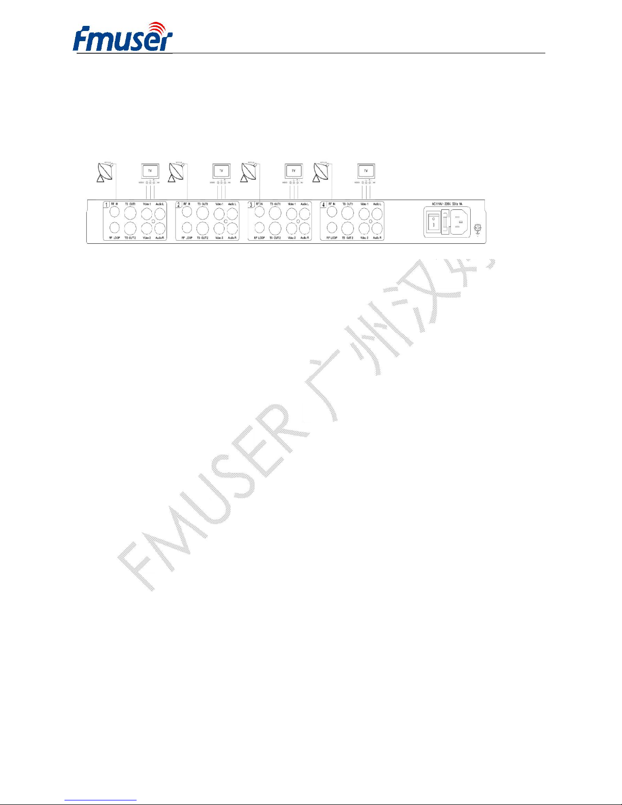
2.3 Installation collection illustration
The FUTV4031A 4 to 4 FTA Satellite Receiver installations is illustrated as follows:
1. Firstly, user should check whether the RF IN connector is in good condition, and
ensure that the internal cable axis and grounding net couldn’t be short. Then, user
can connect the cable with F connectors to RF IN interface.
2. Secondly, user should connect the A/V output of this device to A/V input of TV set
with A/V cable.
3. Lastly, user should connect the power cord to AC socket.
2.4 Wire’s Connection
The grounding wire conductive screw is located at the right end of rear panel, and the power
switch, fuse, power supply socket is just beside ,whose order goes like this, power switch is
on the left ,power supply socket is on the right and the fuse is just between them.
lConnecting Power Cord
User can insert one end into power supply socket, while insert the other end to AC
power.
lConnecting Grounding Wire
When the device solely connects to protective ground, it should adopt independent way,
say, share the same ground with other devices. When the device adopts united way, the
grounding resistance should be smaller than 1Ω.