FNM alpha SM 230 User manual

1
User Manual
alpha® WSN Wireless Measurement System SM 230
®
alpha WSN SM 230
®
alpha WSN BM 110 ®
alpha WSN BM 120 ®
alpha WSN BM 130
®
alpha WSN SM 230-G ®
alpha WSN RM 300-G
®
alpha WSN RM 300

2
3
Table of contents
Safety precautions .......................................................................... 5
Safety precautions for the base module alpha WSN BM 1x0 ................ 6
Safety precautions for the sensor module alpha WSN SM 230............. 6
Safety precautions for the repeater module alpha WSN RM 300 .......... 6
General instructions........................................................................ 7
General product description........................................................... 8
Application example sensor network...................................................... 8
Modules of the wireless measurement system ..................................... 9
Base module ........................................................................................................9
Sensor module.....................................................................................................9
Repeater module ...............................................................................................10
Description of device-specific features ....................................... 10
Base modules......................................................................................... 10
Functional elements and interfaces..................................................................11
Base module with LAN interfaces alpha WSN BM 110..................................12
Base module with USB interfaces alpha WSN BM 120 .................................13
Base module with WLAN interfaces alpha WSN BM 130 ..............................14
Sensor module ....................................................................................... 15
Functional elements and interfaces..................................................................16
alpha WSN SM 230-G ......................................................................................16
alpha WSN SM 230 ..........................................................................................18
Description of the interfaces.............................................................................18
I2C (optional)....................................................................................................18
SPI (optional)...................................................................................................18
UART (optional) ...............................................................................................19
PT1000 .............................................................................................................19
Analogue In......................................................................................................20
Analogue Out ...................................................................................................20
Digital In ...........................................................................................................20
Digital Out ........................................................................................................20
Repeater module.................................................................................... 20
Functional elements and interfaces..................................................................21
alpha WSN RM 300-G ......................................................................................21
alpha WSN RM 300..........................................................................................21
Putting the units into operation.................................................... 22
Delivery status........................................................................................ 22
Initial state of the base module after connecting ................................. 22
Base module alpha WSN BM 110 .....................................................................22
Base module alpha WSN BM 120 .....................................................................22
Base module alpha WSN BM 130 .....................................................................22

2
3
Table of contents
Initial state of the sensor module after starting .................................. 23
Initial state of the repeater module after starting ................................. 23
Mounting................................................................................................. 24
General instructions ..........................................................................................24
Mounting instructions for the base module alpha WSN BM 1x0 ....................24
Instructions for the operation of the PCB version (SM 230, RM 300).............24
Configuration of the interfaces.............................................................. 25
Setting the RS232 interface or settings at the terminal programme ..............25
Setting the USB interface ..................................................................................28
Automatic USB driver installation...................................................................28
Manual USB driver installation .......................................................................31
Checking the USB driver settings ..................................................................35
Link test USB-Port ...........................................................................................36
Setting the LAN interface ..................................................................................36
Installation of the LAN driver ..........................................................................36
Checking the LAN driver settings...................................................................39
Configuration of the LAN interface.................................................................40
Automatic setting of the IP address ...............................................................41
Manual setting of the IP address....................................................................41
Setting Serial-Port-Profile ...............................................................................42
Further settings of the LAN module ...............................................................42
Setting the WLAN interface ...............................................................................43
Automatic setting of the IP address ...............................................................43
Manual setting of the IP address....................................................................44
Setting Serial-Port-Profile...................................................................... 44
Setting the encoding .......................................................................................45
Further settings of the WLAN module ............................................................45
Searching for modules by means of Discovery-Tool .......................................45
Control software and software interface ..................................... 47
Control software alpha data view.......................................................... 47
Installation of the control software alpha data view ........................................47
Short description of the control software alpha data view..............................47
Sensor dialogue.................................................................................................48
Setting the sensor parameters..........................................................................49
Selecting alarm criteria for all sensors.............................................................50
Software interface .................................................................................. 50
Protocol description ..........................................................................................50
Messages from the base module to the PC ...................................................51
Messages from the PC to the base module ...................................................51
Overview of commands.....................................................................................52
Description data bytes.......................................................................................54

4
5
Table of contents
Setting the measuring interval .............................................................. 56
Setting the minimum and maximum capacities .............................................57
Login procedure PC at the base module..........................................................59
Login procedure ..............................................................................................60
Logout procedure ............................................................................................61
CRC calculation .................................................................................................62
Maintenance and inspection......................................................... 63
Base module........................................................................................... 63
alpha WSN BM 110, BM 120, BM 130 ...............................................................63
Sensor module ....................................................................................... 63
alpha WSN SM 230-G ........................................................................................63
alpha WSN SM 230 ............................................................................................63
Repeater module.................................................................................... 63
alpha WSN RM 300-G ........................................................................................63
alpha WSN RM 300 ............................................................................................63
Maintenance .................................................................................. 64
Base module alpha WSN BM 1x0.......................................................... 64
Sensor modules alpha WSN SM 230-G and alpha WSN SM 230 ........ 64
Repeater modules alpha WSN RM 300-G and alpha WSN RM 300..... 64
Battery change ....................................................................................... 64
Battery change housing version .......................................................................64
Battery change PCB version .............................................................................65
Troubleshooting ............................................................................ 66
Base module alpha WSN BM 1x0.......................................................... 66
Sensor module alpha WSN SM 230-G and alpha WSN SM 230 .......... 67
Repeater module alpha WSN RM 300-G and alpha WSN RM 300....... 67
Antennas........................................................................................ 67
Technical data................................................................................ 68
General ................................................................................................... 68
Base module........................................................................................... 68
Sensor module ....................................................................................... 69
Repeater module.................................................................................... 69
Declaration of conformity ............................................................. 70
Glossary......................................................................................... 70

4
5
Safety precautions
Attention!
lThe relevant regulations for installation and operation of electrical installa-
tions have to be observed (e. g. RL 1999/92/EG, RL94/9EG, ElexV, IEC/
EN 60 079-14 and VDE 0100).
l The detailed knowledge and the technically correct realization of the installa-
tion guidelines, safety precautions and functions described in this user manual
are essential to the safety of the operation.
l The safety of the product requires an appropriate transport, an appropriate
storage, installation and operation.
l Interference in the product may only be effected by qualified personnel that
is familiar with the user manual.
l When observing the handling instructions and the safety-related instructions,
no dangers regarding damages to properties and to persons come from the
product in normal case.
l Only use the unit for the allowed application. Mind the EC-type examination
certificate.
l Faulty or improper use as well as the noncompliance with the instructions of
this user manual exclude a warranty by the manufacturer.
Safety precautions
ESD protection measures
Comply with the ESD protection measures according
to DIN EN 61340-5-1/2 when opening the unit (potential
equalization between body and ground of the unit as
well as ground of the casing via high-value resistance
(approx. 1 MOhm) e. g. by means of a usual wrist band).

6
7
Safety precautions
The following regulations have to be observed:
• national safety regulations
• national rules for the prevention of accidents
• national regulations for mounting and installation
• generally approved rules of the technique
• safety precautions of this user manual
• characteristic values and measuring operating conditions of the type and data
plates
• additional signboards on the unit
Avoid to touch conductive parts of the unit.
Do not open the unit, only permit repairs by the manufacturer.
Mind the valid legal provisions for the protection of persons in electromagnetic
fields when installing the antenna.
Safety precautions for the base module alpha WSN BM 1x0
Do not use or install the unit in rooms with explosive materials.
Only use an unshielded Twisted Pair cable (UTP) when connecting the LAN interface
of the alpha WSN BM 110!
Do not cover the base module.
Safety precautions for the sensor module alpha WSN SM 230
Do not use or install the unit in rooms with explosive materials.
In case a battery is inserted, no power supply unit may be connected and the battery
has to be removed in case of operation with the power supply unit.
Safety precautions for the repeater module alpha WSN RM 300
Do not use or install the unit in rooms with explosive materials.
In case a battery is inserted, no power supply unit may be connected and the battery
has to be removed in case of operation with the power supply unit.

6
7
Instructions
General instructions
The wireless measurement system can be operated in countries of the European Union
(EU). Outside the EU, the national regulations of the respective country apply. Only use
antennas that are designated for the frequency range, since otherwise, the operating
license expires and you have to expect appropriate sanctions.
Damages to devices or people that are caused due to the use of our units during
malfunction or normal operation according to our documentation or instructions in any
form, are explicitly excluded from liability.
As well excluded are recourse receivables that can occur indirectly or directly because of
the fault of the manufacturer (delay in delivery, malfunctions that can occur in the period of
guarantee etc.).
Each customer has the opportunity to obtain test units for a system integration test.
The test units are in function equivalent to the standard set (except the standard sets
have better features due to state of the art). The customer has to meet the costs for all
necessary adaptations (software as well as hardware). This is particularly applicable in
case the customer did not make use of a test unit.
Furthermore, our general terms and conditions apply.
Read the user manual carefully to be able to use the wealth of features of your new
Wireless Measurement System.
Information regarding the used trademarks
Microsoft® and Windows® are registered trademarks of the Microsoft Corporation. All
other trade and product names are trademarks or registered trademarks of the respec-
tive companies.
8
9
Product description
General product description
In connection with a base module alpha WSN BM 1x0, the sensor module
alpha WSN SM 230 forms a universal wireless network for the sensor data
acquisition. If required, repeaters (alpha WSN RM 300 or alpha WSN RM 300-G) can
be used for the extension of the range.
The sensor module alpha WSN SM 230 has different interfaces for the connection of
many different sensors or signals and may also be used as repeater module itself.
Recorded measured values are cyclically transmitted to the base module by radio.
This base module is linked with a PC or IP network by means of different interfaces,
depending on the type of base module.
For displaying the measured values and events and the setting of the parameters the
sensor modules, the PC software alpha data view is available.
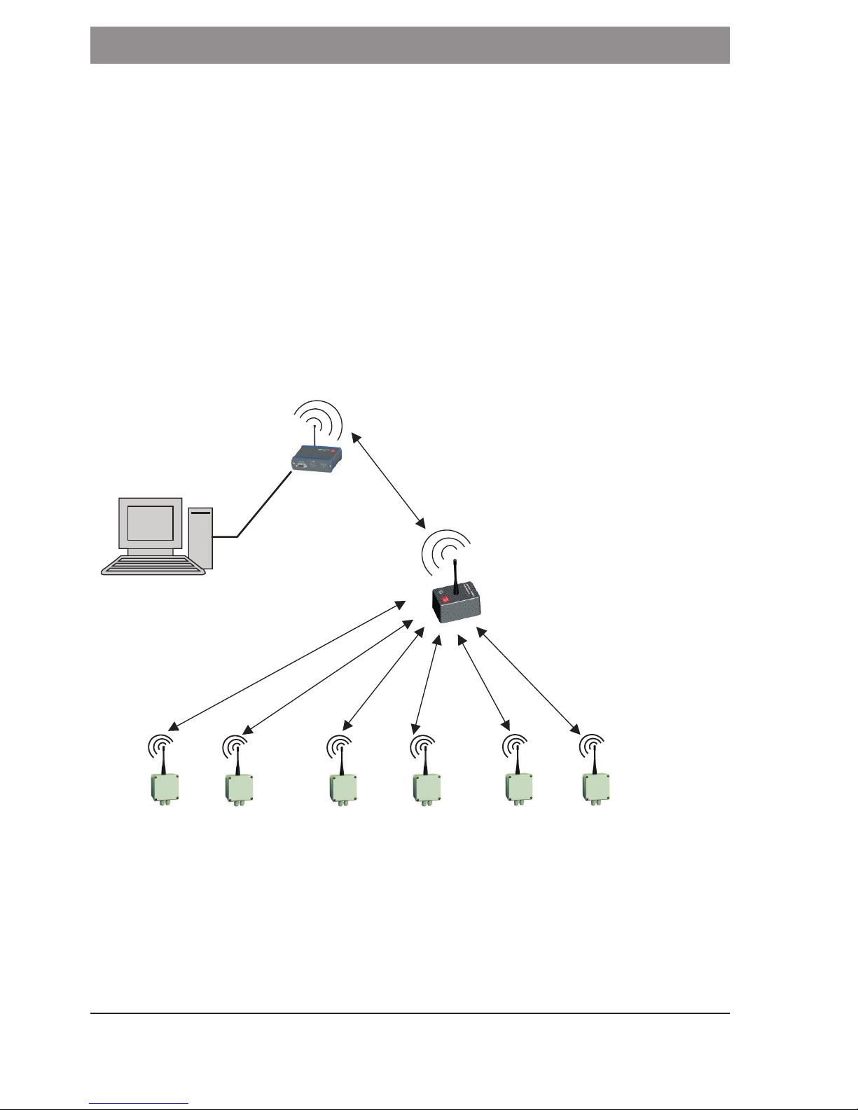
Application example sensor network
Fig.: Example sensor network

8
9
Product description
The sensor data acquisition is often connected with much installation work (laying of a
multitude of cables in areas that are often impracticable and separated) and / or high
personnel expenditure (manual reading of single sensors, interpretation of the measur-
ing results regarding exceeding of the limit etc.). In both cases, considerable financial
expenses arise.
A reasonably priced, flexible alternative that can be adapted to special requirements is
the sensor network alpha WSN from FMN.
Depending on the measuring interval, a total of up to several hundred measuring points is
possible. In order to be able to achieve a sufficient coverage or a higher range, repeaters
can be used. They extend the range of the wireless measurement system by far.
Modules of the wireless measurement system
Base module
The base module receives the transmitted data of the sensor modules and transfers
these over a RS232, USB, LAN or WLAN interface to a PC or an IP network.
The RS232 interface is available at all module versions.
The LAN or WLAN interfaces make the connection to an Intranet or to the Internet
possible and therewith the worldwide inquiry of the measurement data.
At the combination LAN / RS232 (alpha WSN BM 110), the voltage supply will be realized
over an external pluggable power supply unit or over the LAN connection (PoE – Power
over Ethernet) if an appropriate PoE voltage supply is installed in the LAN.
At the combination USB / RS232 (alpha WSN BM 120), it is possible to realize the voltage
supply over the USB interface. Alternatively, the voltage supply can also be realized
over a power supply unit.
At the combination WLAN / RS232 (alpha WSN BM 130), the voltage supply has to be
realized over an external power supply unit.
Sensor module
The sensor module is for the connection of different sensors.
The acquired data is transmitted to the base module by radio and from there, it is
transferred to a PC.
An inquiry as well as setting of the parameters of the sensor modules from base module
(polling) is also possible.
The voltage supply is realised over an internal 3.6 V battery (lithiumthionylchloride,
size 2/3 A). In case the battery voltage is falling below the minimum battery voltage, a
message is sent to the base station. The battery should be changed then. An intelligent
power management guarantees a long battery lifetime.

10
11
Description of device-specific features
Repeater module
The repeater module is for the transmission of the sensor data to the base module. It is
used in case of difficult radio propagation conditions or in case the distances between
sensor and base module are too great.
The voltage supply is realized via an external power supply unit.
A voltage supply over an internal 3.6 V battery (lithiumthionylchloride, size LR14) is
possible, but it is not recommended because of the higher power demand of the re-
peater module.
All versions of the repeater module alpha WSN RM 300 can be used. But a configuration
of the sensor module alpha WSN SM 230 to repeater operation is also possible.
Description of device-specific features
Base modules
The base modules of the sensor network are the interface to the PC network or the IP
network. They receive the data of the single sensor modules and transfer them to a PC.
Connections over RS232, USB, LAN or WLAN are available for this.
The base module can temporarily store up to approx. 45,000 sensor data sets. In case of a
temporary termination of the visualization software or switching off of the PC, the sensor
data is so buffered and is not lost. After starting the visualization software again, the
data is transmitted to the PC.
Furthermore, the base module is equipped with two potential-free outputs (change-over
contacts) that can be controlled from the PC, if required (alarm signalling).
There are two LEDs at every base module. The green LED indicates the operation of the
module (glowing when the module is active) and the red LED indicates correctly trans-
mitted and received packets of data.
Status LED (red) glowing for approx. 50 ms: packet of data transmitted correctly
Status LED (red) glowing for approx. 500 ms: packet of data received correctly

10
11
Description of device-specific features
Functional elements and interfaces
Fig.: Functional elements BM 110, BM 120, BM 130
All base modules have a standardised socket board with potential-free outputs. These
can e. g. be used as alarm outputs. The control is realized over the visualization software
alpha data view. This interprets the received data and sends a command for the activa-
tion of the alarm outputs to the base module, if required. Following, the Pin assignment
of the socket board is described.
Pin Designation Function
1 K1-C 2 relay switch 2 normally closed contact
2 K1-C 1 relay switch 2 central contact
3 K1-C 3 relay switch 2 normally open contact
4 K1-B 3 relay switch 1 normally open contact
5 K1-B 1 relay switch 1 central contact
6 K1-B 2 relay switch 1 normally closed contact
Table: Pin assignment of the socket board at all base modules
Designation Function
Interior contact signal
External contact ground
Table: Assignment of the antenna socket
Colour Function
red status
green operation
Table: Assignment of the LEDs
12
13
Description of device-specific features
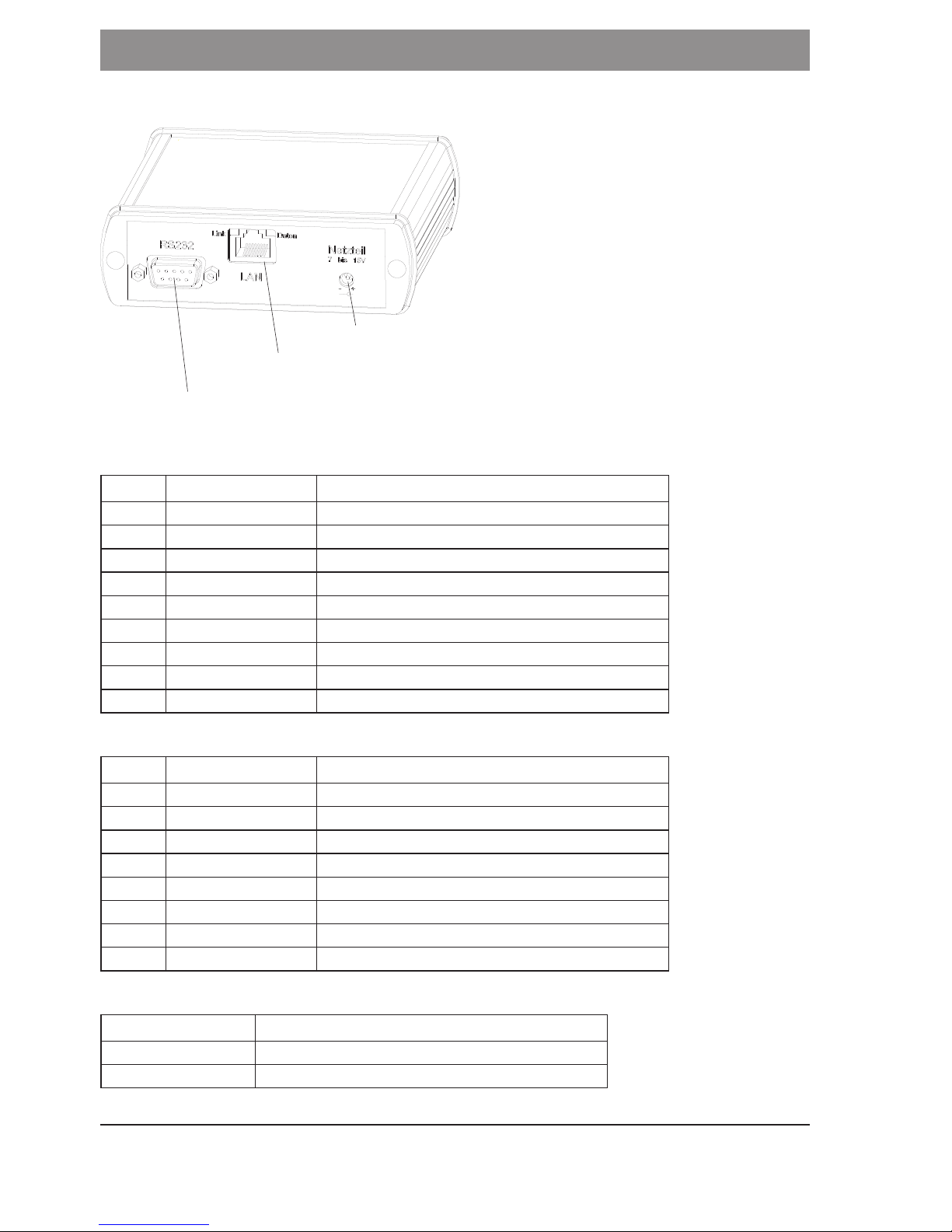
Base module with LAN interfaces alpha WSN BM 110
Fig.: Functional elements BM 110
Pin Designation Function
1 N.C. not connected
2 RXD received data
3 TXD transmission data
4 N.C. not connected
5 GND ground
6 N.C. not connected
7 N.C. not connected
8 N.C. not connected
9 N.C. not connected
Table: Pin assignment of the RS232 socket
Pin Designation Function
1 Tx+ transmission data
2 Tx- transmission data
3 Rx+ received data
4 PoE 1
5 PoE 1
6 Rx- received data
7 PoE 2
8 PoE 2
Table: Pin assignment LAN socket
Designation Function
Interior contact positive supply voltage
External contact ground
Table: Assignment of the power supply unit socket

12
13
Description of device-specific features
Base module with USB interfaces alpha WSN BM 120
Fig.: Functional elements BM 120
Pin Designation Function
1 N.C. not connected
2 RXD received data
3 TXD transmission data
4 N.C. not connected
5 GND ground
6 N.C. not connected
7 N.C. not connected
8 N.C. not connected
9 N.C. not connected
Table: Pin assignment of the RS232 socket
Pin Designation Function
1 VCC +5 V supply voltage
2 D- data
3 D+ data
4 GND ground
Table: Pin assignment USB socket
Designation Function
Interior contact positive supply voltage
External contact ground
Table: Assignment of the power supply unit socket
14
15
Description of device-specific features
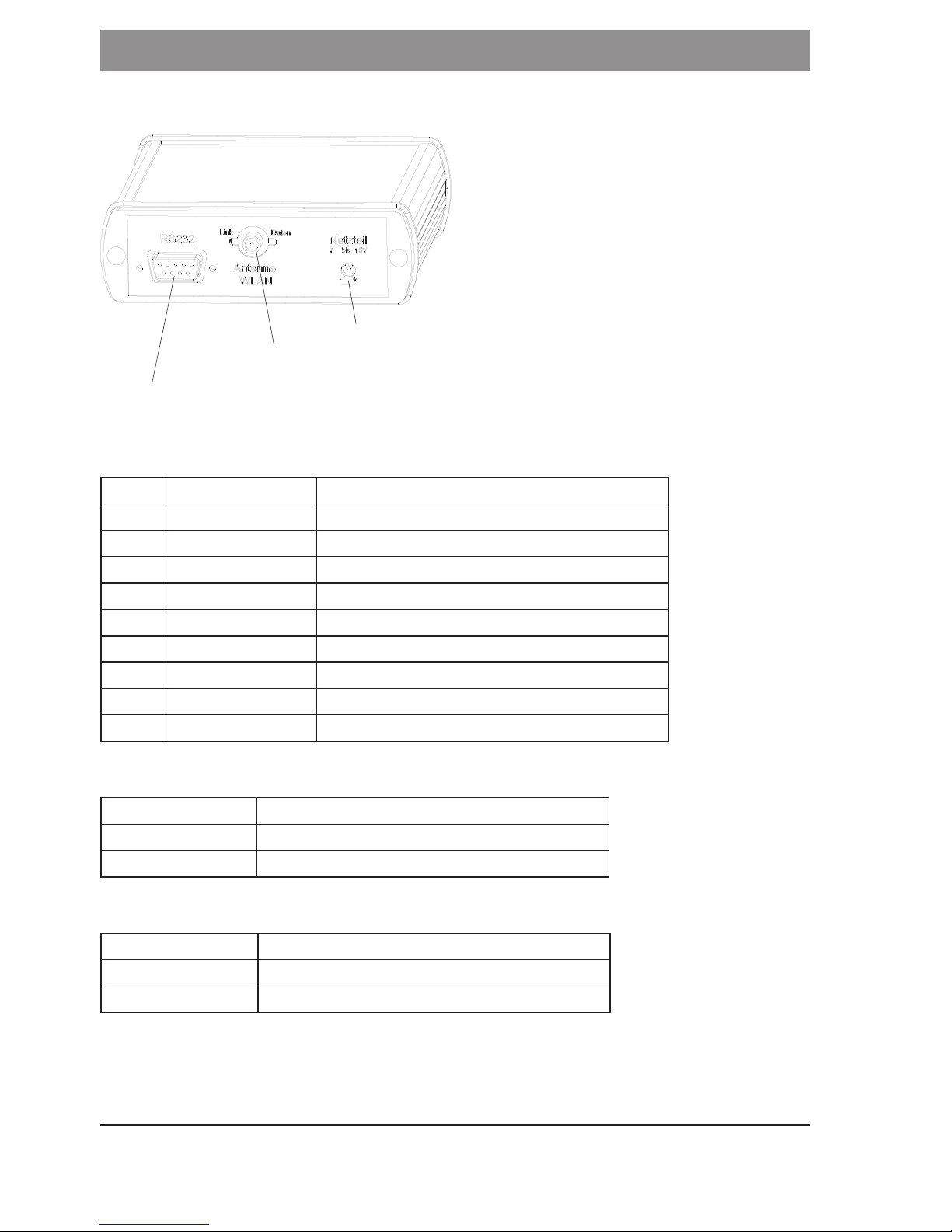
Base module with WLAN interfaces alpha WSN BM 130
Fig.: Functional elements BM 130
Pin Designation Function
1 DCD received signal detected
2 RXD received data
3 TXD transmission data
4 DTR terminal ready
5 GND ground
6 DSR readiness for operation
7 RTS activate transmit unit
8 CTS ready to send
9 N.C. not connected
Table: Pin assignment of the RS232 socket
Designation Function
Interior contact signal
External contact ground
Tabelle: Assignment WLAN-antenna socket
Designation Function
Interior contact positive supply voltage
External contact ground
Table: Assignment of the power supply unit socket

14
15
Description of device-specific features
Sensor module
Different sensors can be connected to the sensor module SM 230. Two 16-pole terminal
strips are available for this.
Sensor cables with a cross section of 0.08 - 0.5 mm2 (AWG 28-20) can be connected.
The cable terminations should be stripped 5 - 6 mm. At the housing versions, the sen-
sor cables have to be led through the cable gland and have to be connected to the
appropriate interface.
The different connection possibilities are summarised in groups in the following table.
Bus
optional
Standard sensor Inputs Outputs
I2C PT1000 2 wire 2 x analogue
0 - 2.5 V
2 x analogue
0 - 2.5 V
SPI PT1000 3 wire 1x analgoue
0 - 10 V
2 x digital
UART PT1000 4 wire 2 x digital
In case of need, all connections can be used simultaneously. Furthermore, the voltage
supply is possible over these terminal strips.
The sensor modules are optionally equipped with a switch off function that can be
controlled over the sensor interface.
The sensor module SM 230-G is available in an IP65 housing, the sensor module
SM 230 is available as PCB version.
The user can determine the measuring interval of every single sensor module in the
range of 10 s…1 year. The respective sensor module always sends latest measured
values after expiration of this time (also see chapter "Control software and software
interface").
Capacities (Min / Max) can also be determined for the analogue inputs as well as for the
PT1000 interface. The sensor module then only transmits valid measured values in case
these are within this range. In case a value out of this range is measured, an invalid
measured value (0x0000) will be sent (see chapter "Control software and software
interface").
The analogue outputs (channel 1 and 2) as well as the UART interface are deactivated
in case of battery operation in order to achieve a lifetime of the battery as long as
possible.
16
17
Description of device-specific features
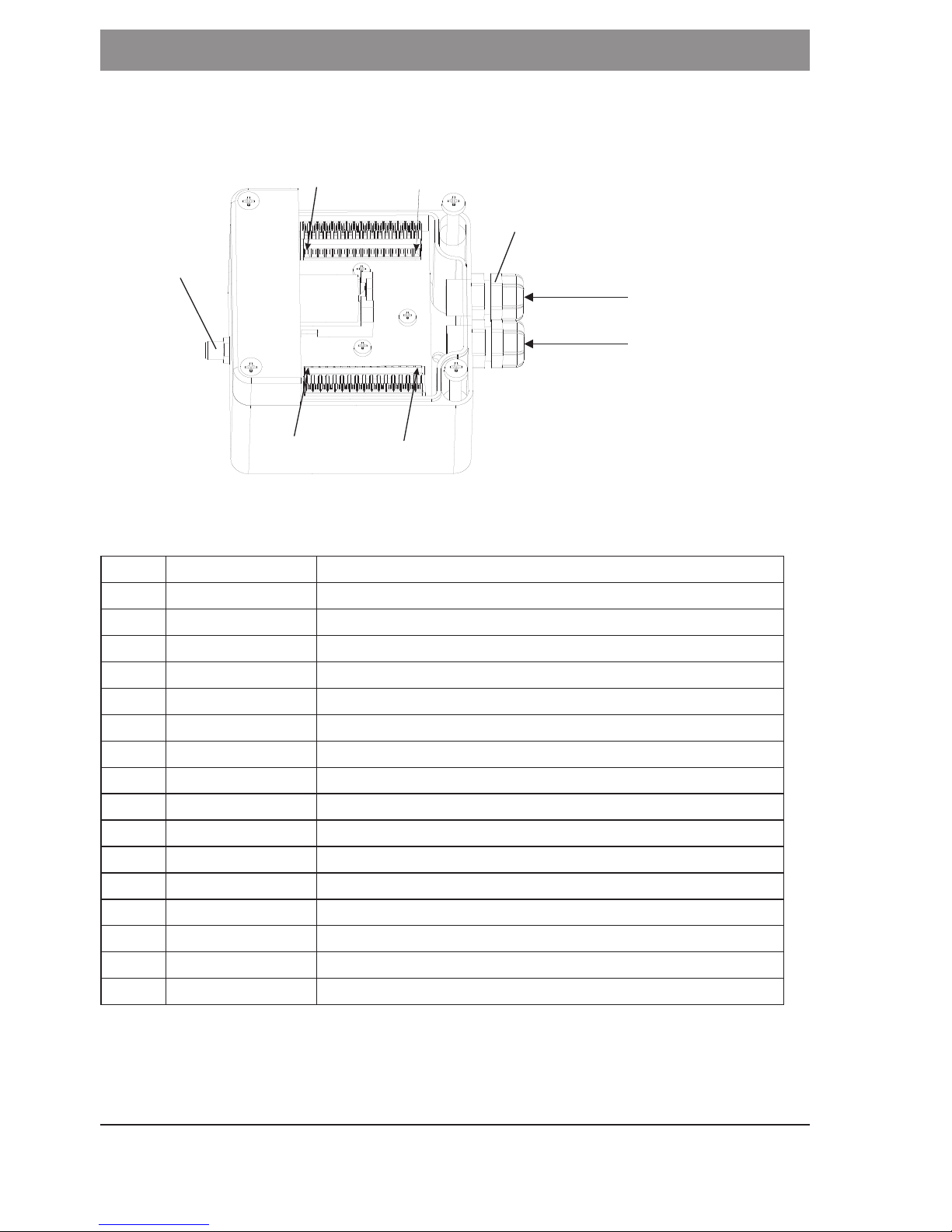
Functional elements and interfaces
alpha WSN SM 230-G
Fig.: Functional elements SM 230-G
Pin Designation Function
X.1 DAC out 2 analogue output channel 2; 0 - 2.5 V *1,*6
X.2 DAC out 1 analogue output channel 1; 0 - 2.5 V *1,*6
X.3 GND ground
X.4 AGND analogue mass
X.5 DIG out 2 digital output channel 2 *1
X.6 DIG out 1 digital output channel 1 *1
X.7 ADC in 2 analogue input channel 2; 0 - 2.5 V *2
X.8 ADC in 1 analogue input channel 1; 0 - 2.5 V *2
X.9 GND ground
X.10 GND ground
X.11 GND ground
X.12 GND ground
X.13 GND ground
X.14 3V output 3 V system voltage *3
X.15 SPI EN enable line SPI bus *1
X.16 SPI CLK clock line SPI bus *1
*1 load resistance ≥ 100 KΩ
*2 input resistance 1 KΩ
*3 max. 1 mA
*6 deactivated in the delivery status

16
17
Description of device-specific features
Pin Designation Function
Y.1 I2C CLK clock line I2C bus *1
Y.2 I2C Data data line I2C bus *1,*2
Y.3 SPI out data output SPI bus *1
Y.4 SPI in data input SPI bus *2
Y.5 +12V positive supply voltage
Y.6 ON/OFF switching input activation / disconnection SM 230 *4
Y.7 TxD data output UART *1,*6
Y.8 RxD data input UART *1,*6
Y.9 DIG in 2 digital input channel 2 *2,*7
Y.10 DIG in 1 digital input channel 1 *2,*7
Y.11 PT1000 1 PT1000 interface Pin 1
Y.12 PT1000 2 PT1000 interface Pin 2
Y.13 PT1000 3 PT1000 interface Pin 3
Y.14 PT1000 4 PT1000 interface Pin 4
Y.15 ADC 10V analogue input 0 - 10 V *2
Y.16 Vref output reference voltage for ADC and DAC 2.5 V *5
Table: Pin assignment sensor interface
Mind the maximum / minimum level (see chapter "Technical data")
*1 load resistance ≥ 100 KΩ
*2 input resistance 1 KΩ
*3 max. 1 mA
*4 optional
*5 max. 100 mA
*6 deactivated in the delivery status
*7 level see "Technical data"
Designation Function
Interior contact signal
External contact ground
Table: Assignment antenna socket
18
19
Description of device-specific features
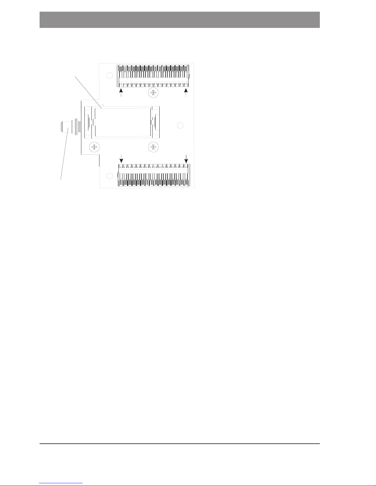
alpha WSN SM 230
Fig.: Functional elements SM 230
Description of the interfaces
I2C (optional)
The sensor module SM 230 works as I2C-Master with a clock speed of approx. 270 Kbit/s.
Addresses with a length of 7 bit are supported. The I2C-packets that are sent to the
sensor module SM 230 are outputted over the interface and the I2C-packets that are
entered at the interface are passed on from the sensor module SM 230 to the base
module. A special message is used for this (also see chapter "Command overview").
SPI (optional)
The sensor module SM 230 works as SPI-Master in mode 0 (4-wire) and with a clock
speed of approx. 300 Kbit/s. Addresses with a length of 8 bit are supported and the
data is each taken over at rising slope. The SPI-packets that are sent to the sensor
module SM 230 are outputtet over the interface and the SPI-packets that are read in
at the interface are passed on from the sensor module SM 230 to the base module.
A special message is used for this (also see chapter "Command overviews").

18
19
Description of device-specific features
UART (optional)
The UART interface is a standard UART interface in 2-wire technology. The data is sent
and received serially in duplex method. The interface is configured as follows:
• data rate: 115,200 baud
• data bits: 8
• stop bits: 1
• parity: without
• handshake: without
But please mind that no duplex operation is possible over the radio interface since no
separate channels for go-and-return channel are available.
PT1000
A 2-wire connection is possible by default. If desired, a 3- or 4-wire connection can also be
realized by an optional adjustment of the hardware.
Following, you can see the appropriate connecting diagrams.
Fig.: 2-wire connection Fig.: 3-wire connection (optional)
optional switch off function on / off
Fig.: 4-wire connection (optional) closed switch: unit in operation

20
21
Description of device-specific features
Analogue In
The analogue inputs are for measuring analogue voltages (e. g. level transmitter).
There is a total of three analogue inputs available, two of them can be operated in the
range 0 - 2.5 V and one can be operated in the range 0 - 10 V. The analogue inputs
refer to AGND.
Analogue Out
The analogue outputs are for the activation of actuators with analogue interface. They
can be operated in the range 0 - 2.5 V and refer to AGND. Two analogue outputs are
available.
Digital In
The digital inputs are for measuring digital signals (e. g. limit switch, state signals). Two
digital inputs are available.
Digital Out
The digital outputs are for the switching of actuators or for the status output. Two digital
outputs are available.
Repeater module
The repeater module has the function to transfer the data within the network. In case
a sensor module is too far away from a base module to reach it directly, the range can
be raised by using a repeater. Thereby, it is possible to set up spatially long-range net-
works by means of sensor modules with low transmitting power. This raises the energy
efficiency and therewith considerably raises the lifetime of the battery.
The repeater modules have to send more often than sensor modules and have to be
ready to receive all the time since they possibly transmit packets of data of several
sensor modules. They are as a rule firmly installed at topological favourable points and
are fed by a power supply unit. In case of need, battery operation is also possible over
a short period of time.
The repeater module RM 300-G is available in an IP65 housing, the repeater module
RM 300 is available as PCB version.
When setting up the network, you have to mind that the number of repeaters in the
network is kept low in order not to stress the network excessively by manifold packet
forwarding.
Repeaters should also be installed in places with good radio propagation conditions
(e. g. isolated, elevated mounting places). This raises the range and the quality of the
whole network.
Table of contents
Popular Measuring Instrument manuals by other brands


dynasonics
dynasonics 901 Series Operation & maintenance manual

Valeport
Valeport fastCTD operating manual

Bender
Bender COMTRAXX MK800 operating manual

Thermo Scientific
Thermo Scientific appliedbiosystems SeqStudio Flex Series user guide

Bresser
Bresser 7007410CM3000 instruction manual

BANTE
BANTE Bante321 instruction manual