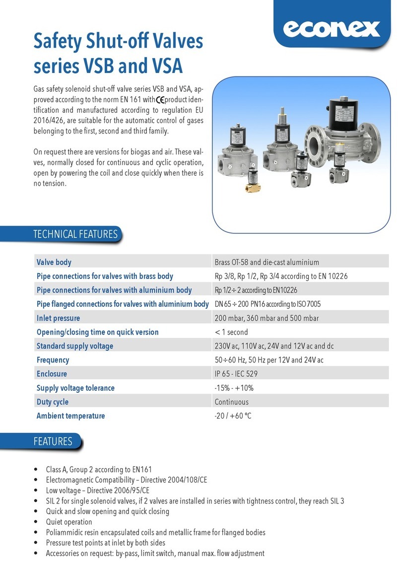
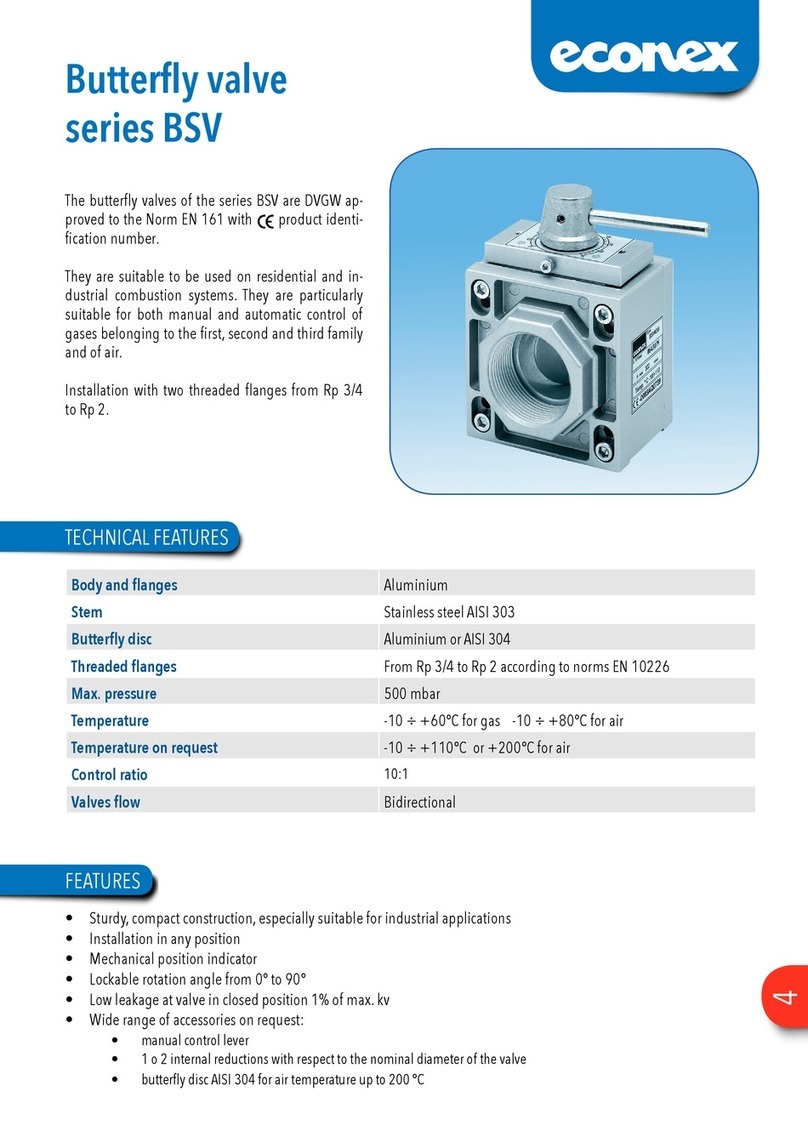
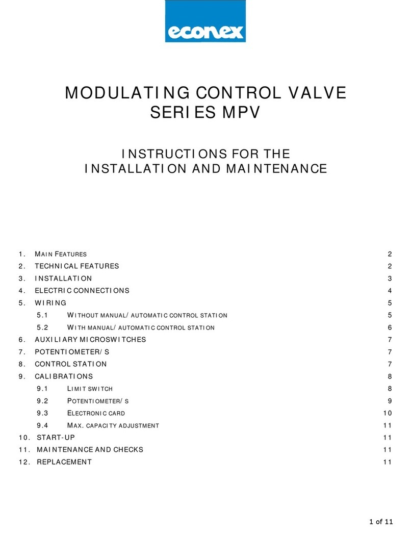
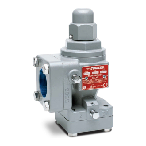
Econex MDV Series User guide

ASSEMBLING AND SERVICING INSTRUCTIONS
~
1) GENERALFEATURES Page 1
2) WARNING Page 1
3) TECHNICAL DATA Page 1
4) INSTALLATION Page 1
5) WIRING Page 2
6) CABLE CONNECTIONS Page 2
7) AUXILIARY MICROSWITCHES Page 3
~8) FEEDBACK POTENTIOMETER/S Page 3
9) CONTROL ST ATION Page 4
10) SETTINGS Page 4
11) OPERATING Page 6
12) MAINTENANCE ANO CHECKS Paga 6
13) REPLACEMENT Page 6

1. GENERALFEATURES
Modulating valves of the Series MDV (Modulating Disc Valve) are newly conceived and are approved DIN
DVGW -EN 161 specifications in order to be used in residential and industriai combustion systems.
They are particularly suitable for the proportional regulation of the quantities of non-corrosive combustible ga-
ses such as natural gas, town gas, LPG and alI other combustibles belonging to the first, second and third fami-
Iy and air.
The gear motor is provided with an single fase, bidirectional electric motor with high static and maintaining tor-
que for 3-position control or electronic control with input signal GT10 V or 4+-20 mA.
The linear rating is obtained thanks to the patented particular shutter disks, rotating on the same axis.
The linear rating is obtained by the linear ratio between the adjustment run and the stream volume according
to the geometry of the adjustment disk's opening.
12 orifice sizes are available, according to the servicing functions. They are alI interchangeable without remo-
ving the valve from the pipeline.
& wARNING
2.
Installation, wiring, adjustment and maintainance of the valve must be carried out esclusively by skilled and
authorized service technicians.
Non proper installation ,adjustment, changes, use and maintainance may cause damages to the the personnel
or to the equipment.
lation of electrical devices and gas systems.
3. TECHNICAL DATA
Max. pressure : 1 bar
Nominai servicing pressure : see coding according to section
Valve group : 2
Ambient temperature: -10°C to + 60° C
Ratio : 25:1
Threadedflanges : 3/4to2 ISO7-1: 1982
Ratingfeature : linear
Valve: without zero closure
Standard supply voltage : 230 V -50/60 Hz
110V -50/60Hz
24 V -50/60 Hz
Electricalprotection : IP54 according to EC 529
Duty cycle : continuous 100%
Terminai head : 2 x Pg 13.5
Opening/closing time : 60 seconds for 90° at 50 Hz
Electriccontacts' ratingof end and auxiliary switches : 5 (1) A/250 V a.c.
Available feedback potentiometers : 150,1000,2500 Ohm
INSTALLA TION
4.
4.1 Make sure that alI operating data indicated on the valve plates correspond to those of the system.
4.2 When installing the valve be sure that there is sufficient clearance abave the gear cover and that it can be easily
accessible in arder ta perfarm wiring and switches adjustment.
4.3 The installation of a filter behind the valve MDV must be also foreseen.
Remove the protection plugs from the threaded flanges.4.4
Screw the threaded flanges ta the entry and exit pipes by using exclusively sealing materials suitable far gas.4.5
Install the valve without electric tension.
4.6
Respect the gas flow direction indicated by the arrow on the valve body.4.7
1

The installation of the valve MDV can be performed in any position.
4.8
The valve MDV can be installed in any location included in the range of electrical protection IP 54 except where
acid fumes or other deteriorating vapour might attack the metal parts or where gas leaks or explosive vapours
are present in the atmosphere.
4.9
Do not use the valve as lever.
5. WIRING
5.1 Wiring and earthing are to be performed according to local prescriptions.
5.2 Far acceding ta the internai terminai baard and far wiring remave the cover by laasening the 4 fixing screws.
Before servicing ensure that powersupply isdisconnetted by means ofthe two-pole-switch (phase and neutral);
in case of non-observance, damages to people and to the equipment may occur.
5.3
5.4 2 threaded hcles far the fitting cf the conduit plug PG 13.5 are present at the bcttcm cf the gear mctcr .
AlI wires must comply with !oca! prescription and, in any case, their section must not be smaller than 1.5 mm2,
5.5
5.6 The wiring diagrams are reported on the plate inside the cover.
The auxiliary microswitches are S.P.D.T. (single-pole double through) and are voltage-free.
5.7
The resistance values of the potentiometers installed are indicated on the identification plate.
5.8
Ensure that power supply and system frequency correspond to the values indicated on the valve plate.
5.9
The low-tension signall cables (tension lowerthan 48V) must be laid separatelyfrom the highertension conduits
(tension higher than 48V). In case they are laid in a single channel, screened cables must be used.
CABLE CONNECTIONS
6.
The wirings diagrams refer to the valve in position "closed"
Without manuaVautomatic control station.
6.1
-SCHEMA S3
~ Form 940909
84 Pot.A
-r$-
Poi.B
-c7f-
/--O!
, ,
Terminai board
Terminai-:!:=; : earthing
Terminai 1 : N= neutral
Terminai 2 : by tension the valve closes
Terminai 3 : by tension the valve opens
Terminai 1 6 : answer signal when the valve reaches the position "open"
Terminai 17: answer signal when the valve reaches the position "closed"
2

With manuaVautomatic control station
6.2
_SCHEMAS4
~Form940909
---j--'"""-,
Poi.B
.c71-
S3 84 Pol.A
-r}p-
/-O! !-Oi
.--';---, :
, , ,
~~~
L1
N
6.2.1 Terminai board
Terminai -:;:- : earthing
Terminai 1 : N=neutral
Terminai 2: by tension the valve closes
Terminai 3 : by tension the valve opens
Terminai 4: for manual electric control
Terminai 16 : answer signal when the valve reaches the position "open"
Terminai 17 : answer signal when the valve reaches the posiiton "closed"
6.3
6.3.1
Auxiliary microswitches
Terminai board
Terminai 2 O: common contact of the auxiliary microswitch S3
Terminai 21 : contact normally open of the auxiliary microswitch S3
Terminai 22 : contact normally closed ot the auxiliary microswitch S3
Terminai 23 : common contact of the auxiliary microswitch S4
Terminai 24 : contact normally open of the auxiliary microswitch S4
Terminai 25 : contact normally closed of the auxiliary microswitch S4
6.4
6.4.1
Potentiometer /s for answer signal of Pot. A and/or Pot. B position
Terminai board
Terminai 30: max. value
Terminai 31 : slider
Terminai 32 : min. value
Terminai 33 : max. value
Terminai 34: slider
Terminai 35 : min. value
The schema refers to the valve in position "closed"
AUXlLIARY MICROSWITCHES
7.
On request the valve can be supplied with 2 auxiliary microswitches which can be adjusted in any position.
7.1
The microswitches are voltage-free.
7.2
The cantact rating is 5 N250 A.c. with far Ohm laad and 1 N250 V c.a. far inductive laad.
7.3
For adjusting the auxilairy microswitches' cams procede as for endswitches' cams as indicated in paragraph
10.1 chapter 10 "SETTINGS"
7.4
8. FEEDBACK POTENTIOMETER/S
r-- On request the valve can be supplied with 1 or 2 independent feedback potentiometers (Pot. A and/or Pot. B)
provides indication of the valve position.
8.1
3

8.2 The resistance value of the potentiometer is indicated on the identification plate. ,
Ifthe resistancevaluedoes notcorrespondtotheonewished, procedeas indicated inparagraph 10.2ofchapter
10 "SETTINGS".
8.4 Power consumption is 2 W per potentiometer.
CONTROL STATION9.
9.1 The contrai station allows the manual electric contrai of the valve.
9.2 Phase L1 must be connected to terminai No.4.
The switch AUTO/MAN is supplied by the factory set on position AUTO O9.3
Position the switch AUTO/MAN on manual position shown by the hand picture I~.9.4
Switch-ON/switch-OFF as follows:
9.5
By pushing the switch towards the symbol ..the valve opens (cam 2 regulates the desired end position
"OPEN").
By pushing the switch towards the symbol the valve closes (cam 81 regulates the desired end position
"CLO8EO").
By positioning the switch in the middle the valve motor does not run.
IMPORT ANT: once the operations for the manual electric control of the valve are over, reset the switch
AUTO/MAN on position AUTO O.
10 SETTINGS
10.1 Endswitches
The valve MDV is supplied by the factory set on position "CLOSED". The endswitches are adjusted in such
a way to reach valve position "CLOSED" and valve position completely "OPEN".
10.1.2 If a smaller opening of the valve is desired it is necessary to operate on cam 82. ,
Far cam adjustment the praper key supplied with the valve equipment and installed inside the gear matar is
ta be used.
10.1.4 Use the key from the right side, introducing the pin into one of the holes on the sides of the blue cam of the cam
involved and lever it to the desired position.
4

If the blue cam is in a behind position use at first the lever on its curved side to move the blue cam to a more
suitable position to perform the adjustment.
10.1.5
".-
In order to make the adjustment easier it is recommendable to refer to the mechanic position indicator disk;
the valve is closed when the mechanic indicator is on position O,the valve is completely open when the mecha-
nic indicator is on position 90.
10.1.6
10.1.7 Cam adjustment is possible in both directions.
When the lever raller far switching the micraswitch is at the battam af the cam hausing the ratatian af the electric
matar staps.
10.1.8
10.1.9 Remove the key before running the gear motor.
10.1.10 The blue cam can be also dragged by means of a small screwdriver by operating on the proper notches.
10.1.11 A valve rotation higher than 90° is absolutely to be avoided not to damage the adjustment disks and/or not to
torce the rotation ot the potentiometer shaft.
Potentiometer/s
r10.2.1 The potentiometer shaft is frictioned and is accessible from the upper side inside the gear motor
Disconnect the cables connected with the modulating system from the respective terminals No.30, 31 and
32 (Pot. A) and, if necessary, No.33, 34 and 35 (Pot. B).
10.2.2.
10.2.3 By means of a suitable screwdriver with 5 mm cut rotate the potentiometer shaft and measure the resistance
value of OOhm between terminals No.31 and 32 and, ifnecessary ,also between terminals No.34 and 35 when
the valve is closed.
10.2.4 By rotating the.2°tentiometer:
.clockwise U : the resistance value increases
.counter clockwise O: the resistance value decreases
The gear box between the gear motor shaft and the potentiometer shaft is foreseen for a 90° rotation angle bet-
ween valve position "closed" and completely "open". Hence should the valve opening be reduced with a rotation
angle lower than 90°, the variation of the potentiometer resistance value will be prioportionally reduced.
If,on the contrary ,the rotation angle has been wrongly adjusted over 90° there will be no increase inthe resistan-
ce value beyond the plate maximum value.
5

11. OPERATING
11.1 Before operating the following points of the MDV valve must be carefully checked:
.correct installation with respect to the flow directjon
.tightness of the extemal gas pipes
.correct wiring and earthing
.perfect electric and mechanic functioning by means of openings and closures with main gas tap closed.
.tjghtness of the whole pipeline .
Once these preliminary checks have been performed, the main gas tap can be opened and the functioning
test can be carried out.
12. MAINTENANCE ANO CHECKS
12.1 The MDV valve does not require any particular current maintenance. Both the valve bodyand the gear motor
do not require any lubrication.
It is recommendable to check wiring to avoid detective terminai board contacts and to tasten screws at least
once a year, especially by systems which do not tunction vibration-tree.
13. REPLACEMENT
In case replacement of the valve MDV is necessary, procede as follows:
Close the main gas tap.
Disconnect tension supply to the valve.
13.3 Remove the gear motor cover.
13.4 Disconnect alI electric wiring taking note of cable numeration.
Remove the valve body from the entrance and exit flange by loosening the fastening screws from the respective
nuts.
13.6 Install the new valve proceding as per instructions reported in the previous chapters.
Form950124
6
Table of contents
Other Econex Control Unit manuals
