FNW 1000 WOG Guide

INSTALLATION, OPERATION & MAINTENANCE INSTRUCTIONS
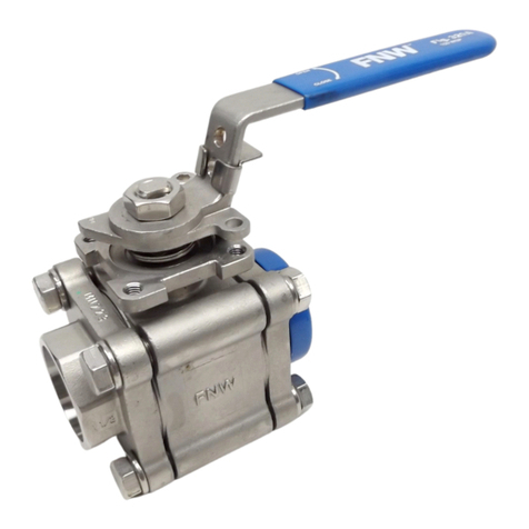
3-Piece Threaded, Socket, Tube & Clamp End Ball Valves
DOC: IOM_FNW3PCBV_ ver_12-2007 Page 1 of 6
INTRODUCTION
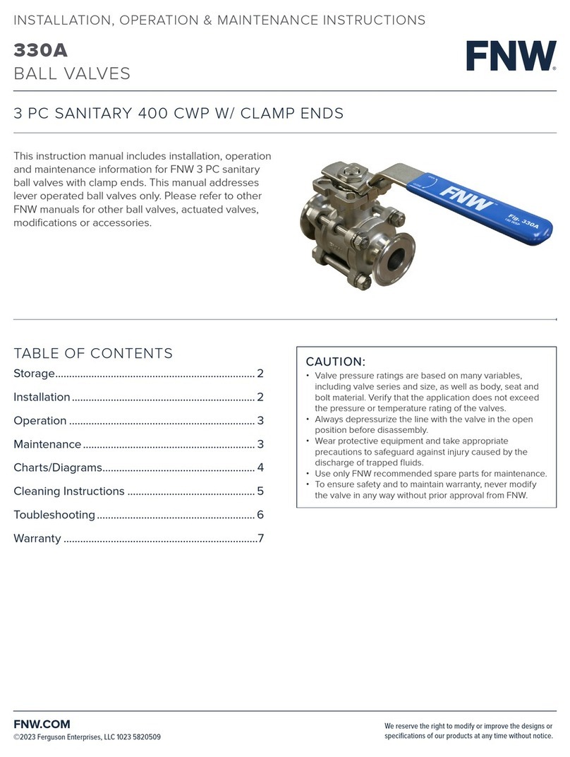
This instruction manual includes installation, operation and maintenance information for 3-piece threaded, socket,
tube, and clamp end ball valves. This manual addresses carbon steel or stainless steel valves.
STORAGE
ATTENTION: Valves are packed in cardboard to avoid possible damage. Smaller valves are also bagged in
plastic. If the valves are not destined for immediate use, the following precautions should be taken:
1. Keep the valves in the full open position. Never leave the valve in the partially open position.
2. Valves should be appropriately protected against dust, dirt, mud, wet, and seawater environments.
3. Carbon steel valves have a black oxide finished. This nontoxic coating is applied to retard rusting during
storage. It is not a substitute for paint or other means of a protective coating. One should be applied to the
valve once installed. Stainless steel valves do not required a protective coating after installation.
PRE-INSTALLATION NOTES
WARNING
To avoid personal injury to your self, fellow workers, or damage to property from release of process fluid, before
installation:
b. Shut off all operating lines to the valve site
c. Isolate the valve site completely from the process
d. Release process pressure
e. Drain the process fluid from the valve site
1. Before installing the valve, inspect the valve body port and associated equipment for any damage that may
have occurred and for any foreign matter that may have collected in shipping or storage. Make certain the
body interior is clean.
2. Before installing the valve, inspect the pipe line and mating pipe, making sure the pipe is free of foreign
material and the ends are clean and have no burrs or pits that could cause leakage.
3. The pipe must be free of tension before and after installation. Alignment is particularly important so as to not
cause undue stress across the body seals. The valve should not be used as the sole source of support for
pipe.
4. If the valve is lubricated (oiled to prevent corrosion during shipping and storage), the lubricant can be
removed with an application compatible solvent if required. Carbon steel valves should have a protective
coating applied after installation.
5. Valves that are tested to ASTM 16.34 may have water trapped between the ball and body cavity. This can be
removed by partially opening the valve, exposing the cavity to the through port of the ball. Allow the water to
drain out.
6. If the valve was supplied with an actuator, secondary support may be necessary. Contact FNW for
recommendations.
7. Cycle the valve a couple of times before installation.
8. When installing valves with square stems, ensure that the port is configured correctly. There is a slot in the
top of the stem that indicates the ports position.

INSTALLATION, OPERATION & MAINTENANCE INSTRUCTIONS
3-Piece Threaded, Socket, Tube & Clamp End Ball Valves
DOC: IOM_FNW3PCBV_ ver_12-2007 Page 2 of 6
9. The valve should be installed in the open position.
10. Valves vary in size, temperature capacity chemical resistance, and pressure capacity. Make sure the valve is
adequate for the application.
11. Standard valves are bi-directional and can be installed in either flow direction.
12. To provide optimum service, the valve should be operated only in the fully open or fully closed position (on/off
service). Throttling service is not recommended.
13. Use only FNW recommended spare parts for maintenance.
14. To ensure safety and to maintain warranty, never modify the valve in any way without prior approval from
FNW.
Threaded Ends
1. Check the valve’s threads and the threads of the connecting parts for compatibility.
2. It is not necessary to disassemble threaded end valves prior to installation.
3. Unless otherwise specified, pipe threads are American National Standard Taper Pipe Threads (NPT) per
ANSI B1.20.1. This standard requires that a pipe sealant be used. Use an anti-seize thread sealant to seal
and prevent galling. Use pipe sealants compatible with valve materials and process fluid. The correct
lubricating sealant used on stainless steel pipe threads is especially important to prevent galling.
4. Do not use excessive amounts of pipe sealant. An excess of pipe sealant can obstruct the pipe or valve or
otherwise hinder the operation of the valve.
5. To prevent distortion or damage to the valve, do not apply torque through the valve. When tightening the
valve, always use a wrench on the end nearest the pipe being tightened. It is preferred that the pipe be
screwed into the valve, holding the valve stationary at the end being connected.
6. Do not over tighten tapered thread ends.
7. Test the operation of the valve, checking for binding or misalignment. Always leak test the system before
using.
Socket and Tube Ends
1. Check fit of pipe to socket end or tube end to pipe prior to welding. Clean and de-burr as needed.
2. With the valve in the open position, tack weld both ends in four equally spaced spots.
3. Loosen all body nuts and remove the body bolts, supporting the body assembly in the process. Carefully lift
out the body assembly and make sure no seats or seals remain on the end caps.
4. Complete the welding of the end caps. Make sure the end caps do not shift during welding. Allow
appropriate time for the welds to cool, and then clean the end caps.
5. Carefully reinsert the body assembly making sure seats and seals are properly located. While supporting the
body assembly, reinstall the body bolts and nuts and hand tighten.
6. Tighten all body bolts according to the information presented in the maintenance section (Table 1).

INSTALLATION, OPERATION & MAINTENANCE INSTRUCTIONS
3-Piece Threaded, Socket, Tube & Clamp End Ball Valves
DOC: IOM_FNW3PCBV_ ver_12-2007 Page 3 of 6
7. Test the operation of the valve, checking for binding or misalignment. Always leak test the system before
using.
Clamp (Quick Disconnect) Ends
1. Ensure that the correct style of clamp and gasket are used.
2. It is not necessary to disassemble clamp end valves prior to installation.
3. During installation, be sure the gasket is properly seated.
4. Do not over tighten.
MANUAL OPERATION
1. Ensure that the valve materials are compatible with the service and that the operating characteristics are
below the valves maximum.
2. Open and close the valve by turning the handle one-quarter turn (90°). Valves may have a locking lever
device. If so equipped, slide the locking plate up the lever before operating.
3. The valve is in the open position when the maximum handle length is parallel to the pipe.
4. The valve is in the closed position when the maximum handle length is perpendicular to the pipe.
MAINTENANCE
WARNING
To avoid personal injury to your self, fellow workers, or damage to property from release of process fluids, before
performing any maintenance:
a. Shut off all operating lines to the valve.
b. Isolate the valve completely from the process.
c. Release process pressure.
d. Drain the process fluid from the valve.
1. Ball valves, if properly used, do not require internal lubrication or maintenance. However, a visual inspection
should be part of a regular maintenance program. A higher frequency of inspection is recommended for
valves operating under extreme conditions. Also, for proper operation it is recommended that the valve be
opened and closed at least twice a year.
2. Before any maintenance, open and close the valve at least once to release the pressure completely from the
valve body.
3. For stem leaks, if the valve has adjustable packing, use a crescent wrench, or spanner wrench as needed, to
turn the packing nut/gland clockwise at quarter-turn intervals until the leak stops. If the packing nut/gland can
not be turned clockwise any further, or if the valve continues to leak, it will have to be replaced or repaired.
NEVER REPLACE VALVE PACKING WHILE THE VALVE IS IN SERVICE.
4. Valves with body seals can be rebuilt by using a “Soft Goods” rebuild kit from FNW.
Assembly and Disassembly
For the following assembly and disassembly instructions, refer to Figure 1. Note: All 3-piece ball valves may not
have the same components listed below. Consult the drawing for the specific valve series for correct bill of
materials.

INSTALLATION, OPERATION & MAINTENANCE INSTRUCTIONS
3-Piece Threaded, Socket, Tube & Clamp End Ball Valves
DOC: IOM_FNW3PCBV_ ver_12-2007 Page 4 of 6
Disassembly
A. Begin with the valve in the open position.
B. Loosen the handle nut (13) and remove.
C. Remove the handle (8).
D. Bend the tab washer (11B) enough so that the gland nut (11) can be loosened. Remove the gland
nut (11).
E. Remove the tab washer (11B).
F. Remove the Bellville washers (12) and packing gland ring (11A).
G. Loosen and remove all body nuts (18), washers (19), and bolts (17).
H. Separate the end caps (3) from the body (1).
I. Body seals (5) may be retained on the end caps (3) or body (1). Remove them.
J. Using the handle (8) loose, turn the valve to half open. Reach through the port opening and remove
the seats (4).
K. Turn the valve to the full closed position and remove the ball (2).
L. Push the stem (6) down into the body (1) and remove it through one of the side body ports.
M. Remove the thrust washer (10) from the stem.
N. Remove the packing (7) from the body’s (1) packing well.
Assembly
A. Place the thrust washer (10) over the top of the stem (6) and slide it down to the bottom.
B. From one of the side body (1) ports, insert the stem, thread end first, into the body, up through the
stem hole.
C. Install packing (7) over the stem (6) and gently work it into the body’s (1) packing well.
D. Install the gland ring (11A) over the stem (6).
E. Install the Bellville washers (12) over the stem (6).
F. Install the tab washer (11B) over the stem (6).
G. Screw the gland nut (11) on to the stem (6). Do not bend the tab washer (11B) up at this time.
H. Add the handle (8) to the stem (6) and loosely secure with the lever nut (13). Make sure the handle is
aligned with its appropriate stops.
I. Turn the handle (8) to the close position.
J. Insert one of the seats (4) into the body (1). Make sure the concave portion of the seat faces towards
the center of the body.
K. From the other side of the body (1), carefully slide the ball (2) in so that the footing groove in the ball
engages the foot of the stem (6).
L. Insert the remaining seat (4) into the end of the body (1), and onto the ball (2).
M. Install the body seals (5) onto the end caps (3) or into the provided recesses on the valve body (1) as
applicable.
N. Insert the body assembly between the two end caps (3) and feed the body bolts (17) through the end
caps and loosely install the body washers (19) and body nuts (18).
O. Ensure that the body assembly is properly centered and that the seats (4) and body seals (5) have
not shifted.
P. Tighten the body nuts (18) and bolts (17) according to the applicable torque chart (Table 1).
Q. Initially tighten the gland nut (11) with a 1/2 to 3/4 turn past hand tight. Bend the tab of the tab
washer (11B) up over the flat of the gland nut and tighten the handle nut (13). If, after testing, there
are stem leaks, follow step 3 above.
R. Test the operation of the valve, checking for binding or misalignment. Always leak test the system
before using.

INSTALLATION, OPERATION & MAINTENANCE INSTRUCTIONS
3-Piece Threaded, Socket, Tube & Clamp End Ball Valves
DOC: IOM_FNW3PCBV_ ver_12-2007 Page 5 of 6
Body Bolt Torques (In-Lbs)*
Table 1
Valve Size
Valve Type/Class 1/4" 3/8" 1/2" 3/4" 1" 1-1/4" 1-1/2" 2" 2-1/2" 3" 4"
1000/800 WOG 86.74 86.74 86.74 104.08 104.08 130.11 147.45 277.56 607.16 607.16 824.00
2000/1500 WOG 86.74 86.74 95.50 95.50 95.50 194.45 194.45 399.35 - - -
Clamp/Tube Ends - - 200.03 200.03 200.03 399.97 399.97 399.97 499.98 899.94 899.94
* These torques are the minimums for proper body sealing. Additional force should not be needed. If
additional force is applied, the user is cautioned to not over tighten, especially to the point of causing the end
caps to bend or otherwise damaging the valve.
Body Bolt Tightening Sequence
Figure 1
General Construction Drawing
Figure 2

INSTALLATION, OPERATION & MAINTENANCE INSTRUCTIONS
3-Piece Threaded, Socket, Tube & Clamp End Ball Valves
DOC: IOM_FNW3PCBV_ ver_12-2007 Page 6 of 6
WARRANTY
1. LIMITED WARRANTY: Subject to the limitations expressed herein, Seller warrants that products
manufactured by Seller shall be free from defects in design, material and workmanship under normal use for
a period of one (1) year from installation but in no case shall the warranty period extend longer than eighteen
months from the date of sale. This warranty is void for any damage caused by misuse, abuse, neglect, acts of
God, or improper installation. For the purpose of this section, “Normal Use” means in strict accordance with
the installation, operation and maintenance manual. The warranty for all other products is provided by the
original equipment manufacturer.
2. REMEDIES: Seller shall repair or replace, at its option, any non-conforming or otherwise defective product,
upon receipt of notice from Buyer during the Manufacturer’s warranty period at no additional charge. SELLER
HEREBY DISCLAIMS ALL OTHER EXPRESSED OR IMPLIED WARRANTIES, INCLUDING, WITHOUT
LIMITATION, ALL IMPLIED WARRANTIES OF MERCHANTABILITY AND FITNESS OR FITNESS FOR A
PARTICULAR PURPOSE.
3. LIMITATION OF LIABILITY: UNDER NO CIRCUMSTANCES SHALL EITHER PARTY BE LIABLE TO THE
OTHER FOR INCIDENTAL, PUNITIVE, SPECIAL OR CONSEQUENTIAL DAMAGES OF ANY KIND.
BUYER HEREBY ACKNOWLEDGES AND AGREES THAT UNDER NO CIRCUMSTANCES, AND IN NO
EVENT, SHALL SELLER'S LIABILITY, IF ANY, EXCEED THE NET SALES PRICE OF THE DEFECTIVE
PRODUCT(S) PURCHASED DURING THE PREVIOUS CONTRACT YEAR.
4. LABOR ALLOWANCE: Seller makes NO ADDITIONAL ALLOWANCE FOR THE LABOR OR EXPENSE OF
REPAIRING OR REPLACING DEFECTIVE PRODUCTS OR WORKMANSHIP OR DAMAGE RESULTING
FROM THE SAME.
5. RECOMMENDATIONS BY SELLER: Seller may assist Buyer in selection decisions by providing information
regarding products that it manufacturers and those manufactured by others. However, Buyer acknowledges
that Buyer ultimately chooses the product’s suitability for its particular use, as normally signified by the
signature of Buyer’s technical representative. Any recommendations made by Seller concerning the use,
design, application or operation of the products shall not be construed as representations or warranties,
expressed or implied. Failure by Seller to make recommendations or give advice to Buyer shall not impose
any liability upon Seller.
6. EXCUSED PERFORMANCE: Seller will make a good faith effort to complete delivery of the products as
indicated by Seller in writing, but Seller assumes no responsibility or liability and will accept no back-charge
for loss or damage due to delay or inability to deliver, caused by acts of God, war, labor difficulties, accidents,
inability to obtain materials, delays of carriers, contractors or suppliers or any other causes of any kind
whatever beyond the control of Seller. Under no circumstances shall Seller be liable for any special,
consequential, incidental, or indirect damages, losses, or expense (whether or not based on negligence)
arising directly or indirectly from delays or failure to give notice of delay.
This manual suits for next models
5
Table of contents
Other FNW Control Unit manuals
