FoamPRO AccuMax 3040 User manual

Models 3040, 3060, 3090, 3150, 3300
INSTALLATION AND
OPERATION MANUAL
Unit
Serial
Number
AccuMax
Multi-Point Injection System
Form 847
Rev. 11/14
All quality FoamPro products are ruggedly designed, accurately machined, carefully assembled, thoroughly inspected
and tested. In order to maintain the high quality of your unit, and to keep it in a ready condition, it is important to follow
the instructions on care and operation. Proper use and good preventive maintenance will lengthen the life of your unit.
ALWAYS INCLUDE THE UNIT SERIAL NUMBER IN CORRESPONDENCE.
FoamPro • 26 Southern Blvd. • Nesconset, NY 11767 USA • 800-533-9511 • FAX 816-892-3178

2
Installation and Operation ManualInstallation and Operation Manual
TABLE OF CONTENTS
SECTION PAGE
1 SAFETY ........................................................................................................................... 3
2 A QUICK LOOK AT HOW THE SYSTEM WORKS.......................................................... 5
3 SYSTEM COMPONENT DESCRIPTION........................................................................ 7
4 INSTALLER SUPPLIED PARTS ...................................................................................... 9
5 INSTALLATION PLANNING .......................................................................................... 12
6 FOAM PUMP AND HYDRAULIC CONTROL VALVE INSTALLATION ......................... 13
7 HYDRAULIC PLUMBING INSTALLATION .................................................................... 16
8 WATER AND FOAM PLUMBING COMPONENT INSTALLATION................................ 18
9 ELECTRICAL EQUIPMENT INSTALLATION ................................................................. 23
10 MAKE SURE EVERYTHING IS WORKING RIGHT........................................................ 31
11 CALIBRATION AND SETUP........................................................................................... 33
12 OPERATION INSTRUCTIONS ....................................................................................... 37
13 MAINTENANCE .............................................................................................................. 43
14 TROUBLESHOOTING .................................................................................................... 44
15 SPECIFICATIONS .......................................................................................................... 51
16 WARRANTY .................................................................................................... Back Cover
NOTE TO SYSTEM INSTALLERS
IMPORTANT: Please provide a copy of the FoamPro manual to the end user of the equipment.
For additional FoamPro manuals, contact by FAX 816-892-3178, web site www.foampro.com,
or call 800-533-9511. Request Form No. 847.

3
Installation and Operation Manual
AccuMax MP
Installation and Operation Manual
The following special notices are used to notify and
advise the user of this product of procedures that may
be dangerous to the user or result in damage to the
product.
NOTE: Notes are used to notify of installation,
operation, or maintenance information that is
important but not safety related.
CAUTION: Caution is used to indicate the presence
of a hazard, which will or may cause minor injury or
property damage if the notice is ignored.
WARNING: Warning denotes that a potential hazard
exists and indicates procedures that must be
followed exactly to either eliminate or reduce the
hazard, and to avoid serious personal injury, or
prevent future safety problems with the product.
DANGER: Danger is used to indicate the presence
of a hazard that will result in severe personal injury,
death, or property damage if the notice is ignored.
• Do not pump at pressures higher than the maximum
recommended pressure. [300 PSI (20.7 BAR)]
• Do not permanently remove or alter any guarding
devices or attempt to operate the system when
those guards are temporarily removed.
• Always disconnect the power source before
attempting to service any part of the pump.
• Release all pressure within the system before
servicing any of its component parts.
• Drain all concentrate and water from the discharge
system before servicing any of its component parts.
• Check all hoses for weak or worn conditions after
each use. Ensure that all connections and fittings
are tight and secure.
• Use only pipe, hose, and fittings from the foam
pump outlet to the injection point, which are rated
at or above 400 PSI (28 BAR) minimum rating, at
which the water pump system operates.
• Use only pipe, hose, and fittings from the hydraulic
oil pump to the foam pump hydraulic motor, which
are rated at least the maximum working pressure or
better as listed in Section 15, and are approved for
mobile hydraulic system use.
• Any electrical system has the potential to cause
sparks during service. Take care to eliminate
explosive or hazardous environments during
service/repair.
• Rotating drive line components may cause injury.
Be careful of rotating components when adjusting
load sense pump compensator.
• Slowly loosen the foam pressure line fittings and
allow the pressure to escape. Protect face and eyes
from any potential spray which may occur.
CAUTION: Do not attempt to operate the system at
or above a temperature of 1600F (710C).
WARNING: Ensure that the electrical source of
power for the unit is a 12- or 24-Volt, negative
ground DC system. Separate 16 AWG or larger
power supply lines must be supplied for the
FoamPro AccuMax components. Power required
for the driver boxes and the controllers must have a
minimum current rating of at least 5 AMPS.
CAUTION: Periodically inspect the pump and the
system components. Perform routine preventive
maintenance as required. Failure to perform routine
maintenance may cause damage to the system.
See the maintenance section of this manual for
recommended maintenance procedures and
intervals between maintenance work.
NOTE: Read and understand these installation
instructions before proceeding with the equipment
installation.
CAUTION: Use only approved petroleum base
hydraulic fluids meeting the specifications as
noted in Section 4. Never mix fluid types. Ensure
all hoses and seals are compatible with fluids used.
Do not use water or glycol-based fluids. Do not use
phosphate ester-type fluids.
CAUTION: Dirt and contaminants are the
primary causes of premature wear and failure in
any hydraulic system. Use extreme care during
assembly and service to keep contaminants out of
the system.
WARNING: Always disconnect the ground straps,
electrical wires and control cables from the Digital
Display Control Module and all other FoamPro
equipment before electric arc welding at any point
on the apparatus. Failure to do so will result in
a power surge through the unit that might cause
irreparable damage.
1 Safety Before attempting to install an AccuMax Multi-Point Injection System,
read all of the following safety precautions and follow carefully.

4
Installation and Operation ManualInstallation and Operation Manual
CAUTION: All DOT, SAE or other applicable
standards must be followed when installing the
hydraulic supply system. Pay close attention
to engine and transmission manufacturer
drive limitations.
CAUTION: Never attempt to cut or lengthen the
molded cables. Doing so will result in RFI/EMI
interference. Contact the factory if molded cables
of a different length are required.
CAUTION: To ensure the integrity of fitting
connections in the hydraulic system, use only SAE
JIC 370flare or equal type hose connections.
WARNING: The hydraulic pump pressure is preset
at the factory for proper operation. DO NOT adjust
the pump pressure relief valves.
CAUTION: The cables shipped with each FoamPro
AccuMax MP system are tested at the factory
with that unit. Improper handling and forcing
connections may damage these cables which
might result in other system damage.
CAUTION: The foam tank low-level sensor must be
utilized to protect the foam pump from dry running.
Failure to do so will void warranty.
CAUTION: When pouring foam concentrate directly
into the foam pump, the inlet strainer is bypassed.
Make sure contaminants are not poured into
pump chamber. Premature pump wear or damage
may result if contaminants are allowed to enter
pump chamber.
CAUTION: Do not run the FoamPro AccuMax 3000
system for more than one minute deadheaded
against the pressure gauge as the foam pump
could be damaged.
CAUTION: When operating the FoamPro AccuMax
MP System in the “Simulated Mode” function, an
outlet for the foam concentrate must be provided.
Otherwise dangerous excessive pressure may
be built up in the apparatus water piping and/or
hoses. This outlet for the foam concentrate can
be provided by turning the “CAL/INJECT” valve to
the “CAL” position. A suitable container must be
provided to collect the foam concentrate.

5
Installation and Operation Manual
AccuMax MP
Installation and Operation Manual
The FoamPro AccuMax Multi-Point injection system is
an electronically controlled, hydraulically driven, foam
concentrate proportioning system designed to provide
the wide range of foam concentrate injection rates
necessary for foam operations.
The FoamPro AccuMax Multi-Point system will
accurately deliver from 0.1% to 10.0% foam concentrate
to each foam discharge injection point independently.
The minimum and maximum rated concentrate flow
rates obtainable are shown in the system specifications
in Section 15.
The FoamPro AccuMax MP system is a flow-
based proportioning system that measures water
flow through a particular discharge and injects the
correct proportional amount of foam concentrate to
maintain the desired percentage in that discharge.
A basic diagram of the FoamPro system is shown in
Figure 2-1. The basic system is comprised of a master
control module and from 1 to 10 line control modules
depending on the design of the apparatus.
The master control module operates and controls the
hydraulic drive foam pump module to monitor and
supply the proper amount of foam concentrate required
by the line control modules. This module consists of a
hydraulic pump, a hydraulic motor-driven foam pump,
a foam flowmeter, a pressure transducer, a foam
tank level sensor, a master driver box, and a master
display controller. The master display controller is in
constant communication with all line control modules
to determine the correct amount of foam concentrate
required and adjusts the hydraulic system to drive the
foam pump to deliver the proper amount. It checks
this overall requirement with the actual foam flow
through the master foam flowmeter feedback loop at
the discharge of the foam pump. The master control
module also monitors the overall foam system pressure
and not only reports it to the user via the display, but
assists in control of the hydraulic circuitry to ensure
that the system does not exceed the design maximum
pressure. There is also a pressure relief valve in the
foam pump discharge circuit for safety.
Each foam capable discharge line requires a line
control module. The line control module consists of a
foam flowmeter, a foam control valve, a foam injection
check valve, a calibrate/inject valve, a main waterway
check valve, a water flowmeter, a line driver box, and a
line display controller. The line controller displays and
communicates the proper information to the master
controller to ensure the proper amount of concentrate
is available to the discharge it controls. The water line
flowmeter measures the water flow and sends a signal
to the line control display. The line foam flowmeter in
the foam discharge line monitors the foam injection
output. Constant comparison of these two information
signals by the computer ensures the desired
proportion of foam concentrate at all times based on
water flow rate, independent of any variations in fire
pump intake or discharge pressures. As water flow
increases or decreases, the foam concentrate rate
of injection is increased or decreased automatically
to correspond to water flow, maintaining the proper
concentrate percentage as selected on the line control
module. It also controls the foam control valve to allow
the proper amount of foam concentrate to be injected
into its discharge line based on the input requirements
supplied by the user and the information supplied by
the foam flowmeter and the water flowmeter in the line
module, regardless of operating pressure.
Each line control module operates independently of
each other and all line control modules communicate
to the master control module for total system
operation. An option for each line control module is the
addition of a pressure transducer for placement into
the discharge water line. This feature is optional and is
for monitoring the discharge pressure only.
Foam concentrate is injected directly into the water
stream on the discharge side of the water pump. It is
then fed as foam solution into a standard fog nozzle,
an air-aspirated nozzle, a straight bore nozzle, or into
a CAFS system, by the main fire pump.
Since the foam is injected on the discharge side of the
fire pump, and check valves are used at installation,
contamination of the booster tank, fire pump, and relief
valve with foam concentrate is eliminated.
Hydraulic power to operate the foam pump is to be
provided by a separate hydraulic pump driven by the
apparatus system. Electrical power to operate the
foam system is provided by the apparatus electrical
system.
2 A Quick Look At How The System Works

6
Installation and Operation ManualInstallation and Operation Manual
Figure 2-1 FoamPro AccuMax Multi-Point System Layout

7
Installation and Operation Manual
AccuMax MP
Installation and Operation Manual
3 System Component Description
1. Master Control Module Components
2. Line Control Module Components
The following components are packaged with the standard FoamPro AccuMax Multi-Point system:
Master Control Display
Master Driver
Control Hydraulic Supply
Pump
Suction Hydraulic Filter
(3040 only)
Hydraulic Motor & Foam
Pump Assembly
Foam
Flowmeter
Foam Line
Relief Valve
Foam Inlet Strainer
Molded Cables
Pressure
Transducer
Line Control
Display
Line Driver
Control
Foam Flowmeter & Control
Valve Assembly
Calibrate/Inject
Valve
Line Waterway
Flowmeter
(Required accessory,
order separately.)
Molded Cables
Foam Injection
Check Valve
Foam Level Sensor

8
Installation and Operation ManualInstallation and Operation Manual
System Accessories Available
Stainless Steel Main Waterway Check Valve
with Drain Port
P/N 3320-0036 1-1/2" NPT thread
P/N 3320-0037 2" NPT thread
P/N 3320-0038 2-1/2" NPT thread
P/N 3320-0039 3" NPT thread
P/N 3320-0040 4" NPT thread
System Placard
P/N 6032-0050
Level Sensor
Vertical Mount
P/N 2510-0028
System Specification Placards
System Part Number
3040 6032-0030
3060 6032-0032
3090 6032-0070
3150 6032-0048
3300 6032-0073
Pressure Transducer
(Optional on Line Control Modules)
Transducer Assy. P/N 2530-0111
Cable Assy. P/N 2520-0100R
Short Data Cable (0.5 M)
P/N 2520-0103R
Long Data Cable (5.0 M)
P/N 2520-0110R
Long Extension Cable (15 M)
P/N 2520-0124
Nesconset, NY 11767 USA
Solid State Contactor
P/N 2510-0043
Low End Option
P/N 3430-0695
Manual Override
P/N 3430-0764
Level Sensor
Side Mount
(P/N 2510-0032)
Foam Flowmeter
Ball Valve
To Cal/Inj. Valve to Container
Pressure Gauge
AccuMax Calibration Kit
Part Number 3430-0831

9
Installation and Operation Manual
AccuMax MP
Installation and Operation Manual
4 Installer Supplied Parts
FoamPro AccuMax MP systems are provided with
major components and accessories required for
installation. Due to differences in chassis and
apparatus configurations, the installer must provide
hydraulic coolers, fluids, reservoir, pipe, hoses, tubing,
wire and fittings to satisfy installation requirements.
The following section lists the specifications for
selection of these components. Before beginning
system installation, read this section thoroughly to
make sure the proper components are selected.
For detailed system installation instructions, refer to
Sections 5, 6, 7, 8, and 9.
CAUTION: All DOT, SAE or other applicable
standards must be followed when installing the
hydraulic system. Pay close attention to engine
and transmission manufacturer drive limitations.
Hydraulic Pump Drive Selection
The foam pump for the FoamPro AccuMax MP system
is powered by hydraulics. Power for the system
comes from hydraulic oil supplied by a hydraulic pump
attached to the apparatus engine. To obtain optimum
performance from the hydraulic motor-driven foam
pump, FoamPro supplies the hydraulic pump and foam
pump hydraulic motor as a matched pair to provide the
proper flow and pressure required with reduced heat
load, torque, and horsepower requirements.
The FoamPro AccuMax MP hydraulic supply pump
will provide the correct fluid flow over the widest range
of engine speeds. See system specifications for the
required pump speed to attain maximum performance
levels. By using a PTO ratio greater than 1.0, the
minimum engine speed for full system performance
could be idle speed.
A transmission PTO should be used to drive the
hydraulic supply pump. Transmission PTOs have
greater torque capabilities and provide adequate
power for the hydraulic pump. Selection of a PTO
transmission with a standard SAE mounting pad
will allow bolting the hydraulic pump directly to the
transmission. The FoamPro AccuMax 3000 hydraulic
supply pump has a standard SAE mounting flange
and shaft (see Section 15 for the pump mounting
information). Standard pump rotation is clockwise
when viewing the hydraulic pump from the shaft end.
Other shaft configurations are available. Check with the
FoamPro factory for other configurations that may be
available. See Section 15 for pump dimensions.
Control of the PTO may be provided by a manual shift
lever, shift cable, or solenoid. The manual shift-type
PTO can be left in gear all the time to circulate oil
as soon as the engine is started since the hydraulic
pump will draw less than 5 hp when operating
in standby mode. The PTO shift can be labeled
“Service Disconnect”.
When selecting a transmission PTO, it is imperative
that consideration be given to frame clearances and
the space in which the hydraulic supply pump is to
be mounted. For new installations, initial design and
planning will eliminate clearance problems. When the
FoamPro AccuMax MP system is being installed as
a retrofit, all clearances must be taken into account.
Consult PTO and chassis manufacturers to determine
dimensions and clearances required.
CAUTION: The use of an accessory drive pad is
not recommended since adequate torque usually
is not available to drive the hydraulic supply pump
and accessories.
Oil Reservoir
A hydraulic reservoir will be required to be installed
in the apparatus. See Section 15 for minimum
recommended reservoir capacity. A larger reservoir
may be installed and is recommended if the apparatus
is to run at maximum capacity for an extended period
of time and to allow air to settle out of the oil.
The reservoir must have a diffuser on the inlet to
prevent entrapment of air into the system. A
particle screen of 100-170 mesh on the oil outlet is
recommended to help keep dirt out of the system. A
baffle to separate the inlet and outlet sections should
be installed in the reservoir. A vented, filtered breather
of sufficient size to allow filling of oil is required and an
oil drain plug is recommended.
The reservoir outlet to the pump inlet should be above
the bottom of the reservoir to take advantage of the
gravity separation and to prevent large particles
from entering the pump. The fluid return should be

10
Installation and Operation ManualInstallation and Operation Manual
positioned so that the flow to the reservoir is discharged
below the normal fluid level, and also directed into
the interior of the reservoir for maximum dwell and
deaeration of the fluid.
A sight gauge with thermometer is also recommended
for easy checking of the oil level and to monitor oil
temperature. The oil reservoir should be mounted away
from heat sources, such as exhaust systems, and be
in a location that allows easy access for checking and
filling the oil.
Oil Cooler
An oil cooler capable of maintaining the temperature
of the hydraulic oil at 160° to 220°F (71° to 104°C)
is required. Use of an air-to-oil radiator-type heat
exchanger should provide adequate cooling for the
hydraulic system oil. An electrically or hydraulically-
driven fan attached to the oil cooler permits mounting of
the oil cooler anywhere fresh air circulation is available.
A thermostat is required to be included for quick
warm-up of the oil in cold climates. Check the system
specifications page in Section 15 for minimum heat load
information to properly size the cooler.
Oil-to-water heat exchangers can be installed, but
they present special problems such as sediment
accumulation, drainage, and overheating when
running in standby mode for extended periods
without discharging water. If a hydraulic oil to water
heat exchanger is to be used, proper maintenance,
monitoring, and pumping procedures must be
followed. The oil-to-water exchangers must be
installed per the manufacturer’s recommendations and
NFPA requirements.
Hydraulic Oil
Ratings and data for the FoamPro AccuMax MP
systems are based on operating with premium hydraulic
fluids containing oxidation, rust, and foam inhibitors.
These premium fluids include premium turbine oils,
API CD engine oils per SAE J183, M2C33F or G
automatic transmission fluids (ATF), Dexron II (ATF)
meeting Allison C-3 or Caterpillar TO-2 requirements.
The recommended hydraulic fluid operating viscosities
are typically 70 to 278 SUS (12 to 60 cSt) for
optimum performance. The hydraulic oil should have
an ISO rating of between 32 to 68 depending on
climatic conditions.
Hydraulic Hoses and Fittings
High pressure hydraulic hoses and fittings are to be rated
to a minimum of the maximum hydraulic pressure rating
found in Section 15. To reduce the potential for leaks at
the hydraulic fittings, use SAE 37° flare JIC type fittings,
SAE straight thread O-ring fittings, or SAE split flange
fittings. See the table for required fitting sizes, minimum
hose size, and minimum hose pressure ratings for the
hydraulic components in Section 15.
Foam Concentrate Suction Lines
Fittings and hoses from the foam tank to the inlet of the
foam pump must be supplied. Use the minimum inside
diameter or larger suction hose shown below for the
corresponding system, depending on the viscosity of the
foam concentrate. Many class B foams are more viscous
and will require one size larger inside diameter hoses.
Model Min. Hose ID
3040 1-1/2"
3060 2"
3090, 3150 3"
3300 4"
Use fittings and components that are rated for 23" Hg
(584.2mm) vacuum and 50 PSI (3 BAR) pressure or
better. The components used must be compatible with
the foam concentrates used. Fittings used must be made
of brass or 300 series stainless steel. Swept elbows and
tees and a Net Positive Suction Head (NPSH) are highly
recommended. If a flushing system is to be used, the
pressure rating of those components subjected to main
water pump pressure are to be rated to 400 PSI (28
BAR) or better.
A drain/air bleed valve should be provided to allow
draining of the tank and easier priming of the foam pump.
Foam Concentrate Discharge Lines
Fittings and hoses from the discharge of the foam pump
to the foam manifold must be supplied by the installer.
Hoses and fittings are to be 1-1/2" (38.1 mm) minimum
for the 3040 thru 3150 systems and 2" (50.8 mm)
minimum for the 3300 system and rated at or above 400
PSI (28 BAR) working pressure. Fittings and hoses must
be compatible with all foam agents to be used with the
system. Use fittings of brass or 300 series stainless steel.
The foam line control assemblies supplied with the
system are to be installed in the foam concentrate
discharge line after the foam manifold. This requires the
line sizes to be at minimum the same as the ID of the
pipe connection before the foam flowmeter of each foam
discharge assembly. Hoses and fittings are to be rated at

11
Installation and Operation Manual
AccuMax MP
Installation and Operation Manual
or above 400 PSI (28 BAR) working pressure. Fittings
and hoses must be compatible with all foam agents to
be used with the system. Use fittings of brass or 300
series stainless steel.
Foam Concentrate Tank(s)
Foam concentrate tanks must be supplied to suit the
capacity required for the apparatus application. The
tank(s) should meet NFPA minimum standards for the
design capacity, including filler size, vapor pressure
venting, and drain facilities.
Check Valves
It is required to install a check valve in the foam
concentrate injection line to prevent foam concentrate
flow from the foam tank to the injection point (at the
main waterway) due to static head pressure. The
concentrate check valve is included with each line
control assembly and is matched to its discharge flow
requirements.
If the system is to be installed in an apparatus where
potable water sources may need to be isolated from
the possibility of foam contamination, there are a few
methods that can be incorporated into the design of the
apparatus or on the outside of the apparatus.
One of those methods is to install check valves in all
water line locations such as flush lines, where foam
concentrate could drain back into the water pumps or
tanks of the fire apparatus, and where the water piping
that will supply foam solution connects to the apparatus
water pump discharge.
Another method is to install a check valve or other
device to between the water pump water tank, and to
the suction inlets to the water pump, or outlets of the
hydrant.
These are just a few of the methods that may be
available.
Drain lines must be provided from all water and foam
solution piping components to prevent freezing in cold
weather. Multiple drain systems that allow individual
drain lines to connect with one another may allow foam
or water to circumvent the check valves. Care must be
taken to avoid this possibility as contamination of the
water tank, foam tank, or water pump may result.
Electrical Requirements
Electrical wiring must be supplied from the main
apparatus electrical system to each individual
display and driver. A 5 or 10 ampere fuse should
be installed in the power line to the system and
is sufficient protection for all displays and drivers.
The individual devices will require a maximum of 5
amperes each at a voltage of 12 to 14.4 volts DC or
24 to 27 volts DC (normal 12- or 24-V DC automotive
system) and is to be connected to each individual
device. Use a standard 14 awg automotive hook-up
wire attached to the supplied WeatherPack 3-pin
connector. Use the grey power cable supplied, with
the 6-pin DIN connector on one end and a 3-pin
WeatherPack connector on the other. The power must
be supplied directly from the battery or the battery
master disconnect switch. Separate wires should be
run for each connection. Braided flat ground straps
are required for ground connections. The flat straps
limit the RFI/EMI interference encountered with radios,
computers or other sensitive electronic equipment.
CAUTION: Always disconnect the ground straps,
electrical wires, and control cables from the
Control Display Modules, the Line Control Drivers,
and Line Control assemblies, and any other
FoamPro equipment before electric arc welding
at any point on the apparatus. Failure to do so will
result in a power surge through the unit causing
irreparable damage and is not covered under
warranty.

12
Installation and Operation ManualInstallation and Operation Manual
Because of the potential differences in apparatus
plumbing and foam system configuration, it is not
practical to depict exactly how each FoamPro AccuMax
Multi-Point system can best be installed onto a
particular apparatus. Most of the information contained
in the following sections, however, will apply to
any situation.
NOTE: It is recommended that you read the
following sections thoroughly before beginning
installation of the FoamPro AccuMax MP system. It
is also recommended that you spend time planning
and designing where and how you intend to install
this unit in the apparatus before beginning the
actual installation.
Determine the locations of the components to be
installed such as foam tank(s), foam pump, oil reservoir,
oil cooler, foam strainers, tank valves, flowmeter(s),
discharge line control assemblies, and hydraulic pump.
Try to place components in locations that require the
least amount of hoses and fittings.
Locate the FoamPro AccuMax system components
in an area that is protected from road debris and
excessive heat buildup. Since the master power
switch and CAL/INJECT valve are components you
may need to access, it is recommended that they be
installed in an accessible location in the vicinity of the
operator’s panel.
The foam pump unit must be mounted below the
discharge of the foam tank(s) to provide for gravity feed
to the foam pump. Locate the foam tank(s) where the
refilling can be easily done with 5 gallon (19 liter) pails,
an appropriate refill system, or other methods suitable
to the end user. Most water tank manufacturers will
build foam tanks into the booster tank. When specifying
integral foam tank(s), make sure provisions are made
for installation of the low tank level sensor as well as
foam suction connections and tank drainage.
Determine a location on the operator panel of
the apparatus for the Control Display Modules.
Consideration must be given for routing the control
cables from the Control Display Modules to the control
drivers, the line control assemblies, and the waterway
flowmeters. If necessary, order longer or shorter cable
assemblies to suit the location demands.
5 Installation Planning
CAUTION: Never attempt to cut or lengthen the
molded cables. Doing so will result in RFI/EMI
interference. Contact the factory if molded cables of
a different length are required.
High viscosity foam concentrates (2000 centipoise and
higher), or inlet lines longer than 10 feet, will require
the foam intake to be one size larger. When larger inlet
piping is used, a larger foam strainer is required to
reduce the pressure drop.
Like any hydraulic system, the FoamPro AccuMax
MP will require cooling and hydraulic fluid filtration.
An oil cooler must be provided for the system and
consideration must be given to the location. The cooler
must be mounted in an area where adequate cool
air can flow over the cooler fins. The ideal location
for an oil cooler is in front of the apparatus engine
radiator. Consult the chassis manufacturer to ensure
adequate fan capacity is available to provide the proper
air flow. Fluid filtration is vital to a hydraulic system. A
suction strainer in the reservoir is required. A filter is
provided on the hydraulic pumps on the 3060 thru the
3300 systems. The 3040 system will require a separate
suction filter as supplied.
When planning the installation, consideration must also
be given to the hydraulic supply pump location, drive
configuration and hose routing.

13
Installation and Operation Manual
AccuMax MP
Installation and Operation Manual
6 Foam Pump/Motor Installation
Hydraulic-Driven Foam Pump Assembly
The foam pump assembly must be mounted in a
horizontal position. The base of the foam pump must
be anchored to a surface or structure that is rigid and
of adequate strength to withstand the vibration and
stresses of apparatus operation. Figures 6-1A thru
C provide the mounting dimensions for the FoamPro
AccuMax foam pump and motor assemblies.
CAUTION: Flexible hose connections are required
between the major FoamPro components and the
main water system. Do not hard plumb the system.
Be sure the hydraulic hoses and the foam concentrate
hoses can be properly routed to the inlets and outlets
on the foam pump. Foam concentrate must gravity feed
to the foam pump inlet from the foam tank(s). The foam
pump must be mounted in an area to avoid excessive
exhaust system heat buildup.
Protection must be provided for the hoses and wiring
to prevent chafing and abrasion during operation of the
foam system.
Protect the foam pump base from excessive road spray
and debris. Although the system is sealed and designed
to be resistant to the harsh environment of firefighting
apparatus, a protected location with easy operator
access is the recommended installation location.
[114]
4.5
[10]
.38
4X
[663]
26.1
[481]
19.0
[211]
8.3
[95]
3.8
[248]
9.8
[181]
7.1
[64]
2.5
Figure 6-1 FoamPro 3040 Pump/Motor Assembly Installation Dimensions
Port B
1-1/6"-12
Straight Thd
O-Ring Port
Port A
1-1/16"-12
Straight Thd
O-Ring Port
1-1/2" NPT
Inlet Port
1-1/2" NPT
Outlet Port
Case Drain Port
7/8"-14 UNC
Straight Thd
O-Ring Port
[80]
3.2
[83]
3.3
[40]
1.6
[197]
7.8
[127]
5.0

14
Installation and Operation ManualInstallation and Operation Manual
Figure 6-2 FoamPro 3060 Pump/Motor Assembly Installation Dimensions
Motor Case Drain
-10 SAE O-ring Port
Motor Case Drain -10 SAE O-ring Port
Port B
-12 SAE O-ring Port
Port A
-12 SAE O-ring Port
2" NPT
Suction Port
2" NPT
Discharge Port
[531]
20.9
[226]
8.9
[51]
2.0
[200]
7.9
[251]9.9 [169]
6.6
[789]
31.1
[308]
12.1
[142]
5.6
[203]
8.0
[235]
9.3
[308]
12.1
[84]
3.3
[42]
1.6
2X
[191]
7.5
3X [95]
3.8
6X
Figure 6-3 FoamPro 3090 Pump/Motor Assembly Installation Dimensions
Port B
1" Split Flange Boss
SAE J518 (Code 62)
Port A
1" Split Flange Boss
SAE J518 (Code 62)
1.0625-12 SAE Str.Thd.
O-ring Boss Case Drain
2X
3" NPT Inlet 3" NPT Outlet
[234.95]
9.25
[531.44]
20.92
[789.25]
31.07
[142.24]
5.60
[251.46]
9.90
[190.50]
7.50
[13.46]
.53
Thru
[50.80]
2.00
[83.6]
3.3
[95.25
3.75
6X
3X
3X
[286.82]
11.29
[307.59]
12.11
[563.68]
22.19
[445.59]
17.54

15
Installation and Operation Manual
AccuMax MP
Installation and Operation Manual
Figure 6-4 FoamPro 3150 Pump/Motor Assembly Installation Dimensions
1.0625-12 SAE Str.Thd.
O-ring Boss Case Drain
Port B
1" Split Flange Boss
SAE J518 (Code 62)
Port A
1" Split Flange Boss
SAE J518 (Code 62)
3" NPT Inlet 3" NPT Outlet
[476]
18.7
[601]
23.7
[846]
33.3
[142]
5.6
[76]
3.0
[84]
3.3
[307]
12.1
[248]
9.8
[229]
9.0
[304]
12.0
[259]
10.2
[191]
7.5
[13]
.5
[569]
22.4
2X
6X
Figure 6-5 FoamPro 3300 Pump/Motor Assembly Installation Dimensions
2X 1.0625 SAE Str.Thd.
Case Outlet
1" SAE Split Flange
Port A
1" SAE Split Flange
Port B
[614]
24.2
[871]
34.3
[142]
5.6
[307]
12.1
[489]
19.2
[84]
3.3
[582]
22.9
[76]
3.0
[304]
12.0
[272]
10.7
[191]
7.5
[13]
.5
6X
3" NPT Inlet
3" NPT Outlet
[248]
9.8
[229]
9.0

16
Installation and Operation ManualInstallation and Operation Manual
7 Hydraulic Plumbing Installation
Figure 7-1 provides some recommended guidelines
for the location of the hydraulic system components.
When making hydraulic component connections,
ensure all applicable DOT and SAE standards are
followed. Use hoses and fittings rated at least the
maximum working pressure listed in Section 15 for
the hydraulic oil high pressure lines. See Section 15
for required fitting sizes, minimum hose size, and
minimum pressure ratings.
The fittings required to connect the hydraulic hoses
to the FoamPro AccuMax MP foam pump motor and
hydraulic supply pump are SAE ORB (O-Ring Boss)
fittings with SAE JIC 37° flare swivel, and SAE Split
Flange port connections.
CAUTION: To ensure the integrity of fitting
connections in the hydraulic system, use only
SAE JIC 37° flare, SAE O-Ring Boss, or SAE Split
Flange-type hose connections.
CAUTION: Use only approved petroleum-based
hydraulic fluids as described in Section 4. Never
mix fluid types. Ensure all hoses and seals are
compatible with fluids used. Do not use water or
glycol-based fluids. Do not use phosphate ester-
type fluids. Other hydraulic fluids such as SAE
10W-40HD motor oil are too viscous for proper
pump performance.
Hydraulic Power Source
The hydraulic power for the FoamPro AccuMax MP
system is supplied by a hydraulic pump mounted on
the fire apparatus engine, transmission, or auxiliary
PTO. The hydraulic pump supplied with the system has
been chosen to provide the required flow and pressure
to drive the FoamPro AccuMax system.
Refer to Section 4 of this manual for further pump and
PTO information and Section 15 for detail dimensions
of the pump. See the table in Section 15 for all proper
hose sizes, pressure ratings, and fittings for the various
hydraulic components supplied by FoamPro.
Figure 7-1 Simplified FoamPro AccuMax 3000 Hydraulic System Diagram (not to be used as a system schematic)
Hydraulic Pump
Suction
Hydraulic Pump
Hydraulic Reservoir
Foam Pump/
Motor
Assembly
Hydraulic Motor
Case Drain
Hydraulic
Oil Cooler
System Return
Hydraulic Pump
Upper Case Drain
Motor Inlet
Cooler Inlet
Motor Return
Hydraulic Pump
Bottom Case Drain

17
Installation and Operation Manual
AccuMax MP
Installation and Operation Manual
Hydraulic Reservoir
The reservoir for the hydraulic system is to conform
to the description in Section 4 and to all SAE and
DOT standards. See table in Section 15 for minimum
reservoir capacity for the unit being installed.
Hydraulic Oil Filtration
Hydraulic fluid filtration is vital to the performance and
life of any hydraulic system. The AccuMax SP systems
are no different. A suction strainer of 100 to 170 mesh
is required in the outlet of the reservoir and should be
sized to accommodate the charge pump flow of the
system without significant pressure drop.
Model 3060 thru 3300 hydraulic pumps have a spin
on filter already installed for that particular pumps
protection. This filter has a Beta 10 rating of 10 to 20.
The Model 3040 system requires a suction filter with a
Beta 10 rating of 10 to 20. The flow rating on the filter
should be at least 25 gpm when used for suction. A
filter is supplied with the system.
CAUTION: Ensure all hydraulic hoses and
components are clean and free of debris.
CAUTION: Ensure hydraulic fluid is clean and free
from contamination when filling and changing the
fluid in the system.
Hydraulic Oil Cooler
An oil cooler is required in the hydraulic system to
ensure proper oil temperature for optimum performance
and to avoid damage to the hydraulic components.
The actual cooler size required will depend on the
system requirements, the location of the cooler, and
the manufacturer of the cooler. Typical oil to air cooler
connections are shown in Figure 7-2. The cooling
requirements for the system being installed are listed in
the table in Section 15.
If an oil-to-water exchanger is used, proper
maintenance, mounting, and operating procedures must
be maintained. A method to circulate cool fresh water
must be provided when the hydraulic pump is engaged.
A drain port must also be provided to prevent freezing
and to allow flushing.
Hydraulic Supply Pump Connections
After completion of the mounting of all hydraulic system
components, hose connections must be made. A table
in Section 15 shows the connector and minimum hose
sizes, and drawings in Section 15 show the connection
ports to use for the hydraulic supply pump. Always use
the uppermost case drain port available.
Pump Adjustment
The supplied hydraulic pump does not require any
adjustment. The pump is adjusted to give you maximum
performance throughout the entire operating range.
Figure 7-2 Oil Cooler Hose Connections
Oil from
Hydraulic
Motor
Oil to
Reservoir
Electric
Fan
Oil
Cooler
Thermostat
Control
Valve

18
Installation and Operation ManualInstallation and Operation Manual
8 Water and Foam Plumbing
The following diagram (Figure 8-1) provides recommended guidelines for the installation of the system components
that handle water, foam concentrate, and foam solution.
Figure 8-1

19
Installation and Operation Manual
AccuMax MP
Installation and Operation Manual
CAUTION: Flexible hose connections are required
between the major FoamPro components and the
main water system. Do not hard plumb the system.
Foam Pump Suction
The inlet hose from the foam tank should be a minimum
of 1-1/2” (38.1 mm) for the 3040, 2” (50.8 mm) for the
3060, 3” (76.2 mm) ID for the 3090 and 3150, and 4”
(101.6 mm) ID for the 3300 and have adequate wall
stiffness to withstand the vacuum of the foam pump
while it is running without collapsing [23” Hg (584 mm
HG)].
Outboard Pickup
An outboard pickup may be adapted to the foam pump
inlet. The pickup should be positioned between the
foam tank shut off valve and the foam inlet line strainer.
A tee the same size as the tank to pump line may be
placed in the suction line with the side leg of the tee
going to the outboard pickup shut-off valve at the panel.
A sealed quick connect-type fitting may be mounted
to the panel for easy access. The outboard pickup
line should not exceed 10 feet and the same line size
and specifications as the tank to pump line should
be utilized. The shut-off valves must be full ported
valves and be air tight. A switch must be provided
to disengage the low level sensor when using the
outboard pickup. This switch may be a separate panel
mount or one that is tied into the pickup valve actuator.
NOTE: The tank shut-off valve must be closed
before opening the outboard valve when switching
to the offboard pickup. The offboard pickup valve
must be closed before opening the tank valve when
switching to the foam tank operation.
Line Strainer
The line strainer provided with the FoamPro AccuMax
MP system is sized properly for most applications.
See Section 4 for further information. The appropriate
strainer is to be installed on the inlet side of the foam
pump.
CAUTION: If a pressurized water flush system
is incorporated, the plumbing exposed to this
pressure must be rated at or above the operating
pressure, or a minimum of 400 PSI (28 BAR).
Master Foam Flowmeter Connection
The Master Foam Flowmeter is to be installed in a
position after the foam pump discharge, as shown in
Figure 8-1, with a minimum of 12 inches (305 mm)
straight run before and 4-inch straight run after the
device. Ensure the flow direction is the same as the
arrow on the side of the flowmeter. Mount the flowmeter
per Figure 8-4.
Pressure Sensor Connection
The pressure transducer used in the master line is to
be mounted in the position shown in Figure 8-1. Note
that the positioning of the sensor should be the same
as found in Figure 8-6. The sensor has a 1/4” NPT
connection into the main foam line.
Foam Pump Discharge Relief Valve
The discharge relief valves on the outlet port of
the hydraulically-driven foam pump is preset at the
factory to ensure optimum performance of the
FoamPro AccuMax system. The bypass line from the
hydraulically-driven foam pump relief must return to
either the foam concentrate tank or a minimum of 5
feet from the inlet port of the foam pump. This will
lessen the aerating of the foam in the event of an over-
pressurization of the system.
Foam Discharge Manifold
The discharge of the foam pump will require a manifold
to disperse foam concentrate to the line discharges.
Use a minimum of 3/4” (19 mm) for the 3040, 1” (25.4
mm) for the 3060, 1-1/2” (38.1 mm) ID pipe with
corresponding tees in line for each discharge line for
Models 3090 and 3150. Use a minimum of 2” (50.8 mm)
ID pipe with corresponding tees for each discharge line
for model 3300.
Line Waterway Flowmeters
The FoamPro AccuMax MP system is designed to
accept flow reading signals from the FoamPro
paddlewheel-style flowmeter.
Outboard Pickup Diagram
Outboard Pickup Line
Switch to disconnect
Level Sensor when in
Outboard
Full Ported
Shut-off Valve
Full Ported
Shut-off
Valve
Strainer
Foam
Tank Driver
Box
Foam
Pump
Assy.

20
Installation and Operation ManualInstallation and Operation Manual
Proper flowmeter sizing is critical to system accuracy.
Select a flowmeter size based on actual flows required,
not standard pipe sizes. Refer to the installation
drawing in Section 15 for proper flowmeter sizing.
The flowmeters require that the amount of turbulence
in the pipe being monitored is as low as possible.
Excessive turbulence produces unstable and inaccurate
flow readings. The following installation guidelines will
help attain the best readings and maintain accuracy of
the FoamPro AccuMax MP system.
1. A minimum 5 times the pipe diameter of straight
run pipe without any fittings is necessary upstream
of the flowmeter. 10 times is better. The following
are the recommended straight run lengths for given
pipe sizes:
Pipe Recommended
Size Straight Run Pipe
1-1/2" (38 mm) 7-1/2 to 15" (191 to 381 mm)
2" (50 mm) 10 to 20" (254 to 508 mm)
2-1/2" (64 mm) 12-1/2 to 25" (317 to 635 mm)
3" (76 mm) 15 to 30" (381 to 762 mm)
4" (100 mm) 20 to 40" (511 to 1016 mm)
2. The downstream plumbing of the water flowmeter is
not as critical, but straight runs without fittings help
maintain accurate repeatable flow readings.
3. Do not mount a flowmeter directly after an
elbow or valve. Valves create severe turbulence
when they are “gated down” as shown in Fig. 8-2.
4. Try to mount the flowmeters in a position that is
accessible for routine inspection and maintenance.
The FoamPro paddlewheel-style flowmeter fittings
are specially designed tees that make inspection and
maintenance of the flow sensor easy. The threads of the
tees are available in NPT with grooved victaulic ends, or
BSP with grooved victaulic ends. In horizontal runs, the
tees should be mounted as close to upright as possible
within the range shown in Figure 8-3.
Foam Line Discharge Assemblies
The foam line discharge assemblies shipped with the
unit are designed to give maximum performance and
accuracy over the full range of operations for each line
and the system. The foam line discharge assemblies
include stainless steel fittings, a foam flowmeter, and
a foam control valve. The foam flowmeters in the
assemblies are to be mounted in the orientation as
shown in Figure 8-4. A straight run of hard piping before
and after the flowmeter is required and is built into each
line assembly with stainless steel fittings.
Calibrate/Inject Valve
The calibrate/inject valve supplied is to be positioned on
the discharge side of each line control valve as shown
in Figure 8-1. This valve must be accessible. The valve
is a 3-way directional control valve that selects where
the output of the foam system will go.
Check to make sure the valve is installed properly. Look
at the ports as you move the selector handle. The flow
should go from the center port to each of the end ports.
The hoses to and from the valve should be the minimum
line control size and be pressure rated to 400 PSI
Figure 8-2 Flowmeter Placement
Figure 8-3 Flowmeter Position Range
Figure 8-4 Foam Flowmeter Positioning
Horizontal Positioning
Vertical Positioning
This manual suits for next models
4
Table of contents
Other FoamPRO Controllers manuals
Popular Controllers manuals by other brands

Trinamic
Trinamic TMC428 Application note

Allen-Bradley
Allen-Bradley Studio 5000 Logix Emulate Programming manual
AfterBurner
AfterBurner GPIO CAPABILITY user manual

Honeywell
Honeywell TheraPro HR90 owner's guide
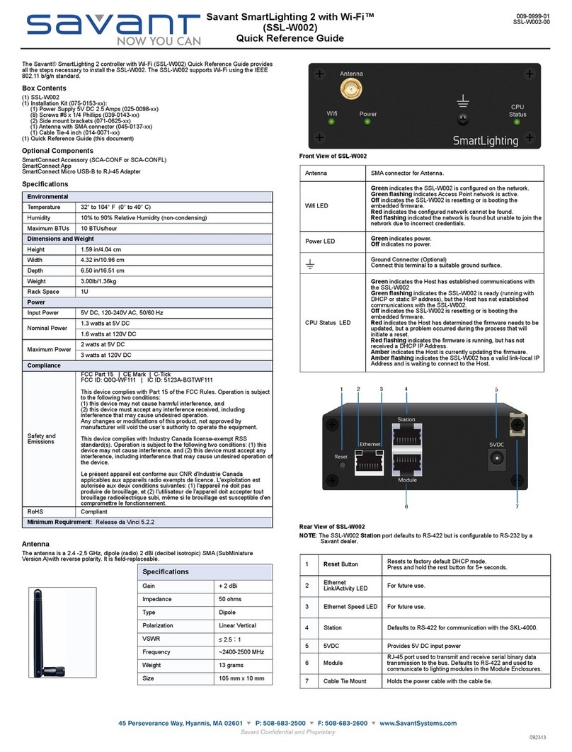
Savant
Savant SmartLighting 2 Quick reference guide
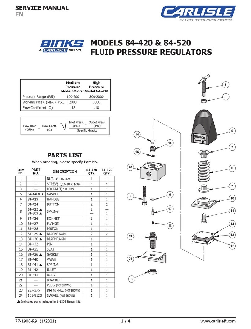
Carlisle
Carlisle BINKS 84-520 Service manual

Parker
Parker PAC120 Series Operation manual

Honeywell
Honeywell CENTRA LINE MERLIN NX Series Installation & commissioning instructions

Siemens
Siemens RMU7*B series operating instructions
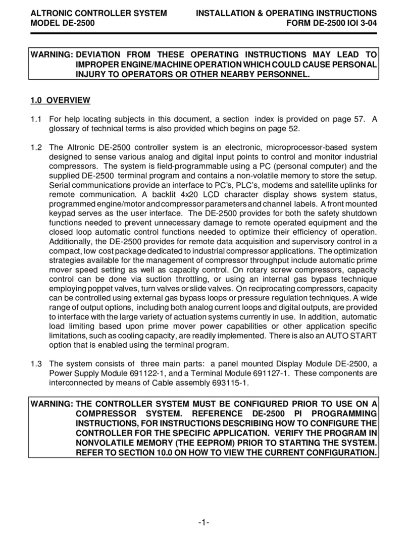
Altronic
Altronic DE-2500 Installation & operating instructions

miniBatt
miniBatt PRO VR user manual
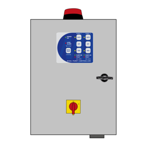
Matelec
Matelec RPC-30030 Owner's operation manual
