manuals.online logo
Brands
  1. Home
  2. •
  3. Brands
  4. •
  5. Inter-m
  6. •
  7. Controllers
  8. •
  9. Inter-m NLM-8000C User manual

Inter-m NLM-8000C User manual

NLM-8000C
ocal Machine
Re r P nel
Fe tures
This device is a wall controller that used by connect-
ing with MR-8000 mounted on NPX-8000. It can se-
lect the sound source and volume, and can expand
up to eight in the mode of Daisy Chain.
Front P nel
3
2
1
OUTPUT 1
INPUT 1
INPUT 2
INPUT 3
INPU
IN
N
I
LM LINK
LM LINK
2
1
1. Displ ying Window
Sound source, volume, and status information of the
channel set at NPX-8000 are displayed.
2. Selecting Switch
It is a switch that can change the sound source and
volume, and select the status information.
It is selected if the switch is turned to control the
value you want and press the switch at the position
to select.
3. Led St tus Displ ying Led
It is ED that displays the operation status of the device.
- Channel mode: GREEN ED is on.
- Volume mode: B UE ED is on.
- Sleep mode: When ed Control is ON, B UE ED
is on. When ed Control is OFF, ED is off.
In case ed Control is OFF, ED turns off.
- Communication error: RED ED is on.
- Setup mode: MAGENTA ED is on.
- Others: RED ED is on at Mute status.
1. Termin tion Switch
It is a switch used in the device connected finally in
case of connecting the device using M port of MR-
8000 by Daisy Chain mode.
2. Lm Link Port
It is the terminal that can connect power supply
(+40V) and communication, audio line.
※ Be sure to use direct cable when connecting INK
of device.
※ For cables, it is recommend to use those below
DCR 100m/9.8Ω.
NO Description
1 CAN – H
2 CAN -
3 N.C
4 DC 40V
5 GND
6 N.C
7 Audio Out+
8 Audio Out-
<RJ45 Termin l Description>
NLM-8000C
ocal Machine
- ID Set
1) Device ID can be set.
2) In case ID is changed, if the selection switch is
pressed for 5 seconds or longer and the display
window ID phrase is changed into ID SET phrase
and ID can be changed.
3) When selection switch is pressed at the state ID value
to change is displayed after turning the selection
switch, Select, Cancel phrases are displayed. If Select
is selected, ID is changed and is cancelled if Cancel
is selected.
- Termin tion
1) You can check the device termination status.
2) This menu can check ON/OFF status of termination
resistance switch only, and the change can be
done only with the termination switch at the back
of the device.
3) If you press the selection switch, it returns to Set-
ting screen.
- Firmw re
1) You can check the firmware version of the device.
- LED Control
Device setup method nd c utions
1. Device B sic Oper tion
- W iting Screen
1) If you connect NPX-8000 and N M-8000C, power
is supplied to N M-8000C, and N M-8000C is
ON.
2) In case ID of N M-8000C collides, ID set window
is displayed. In this case, ID is reset.
※ Refer to 2. Device set explanation or MP-8000
manual for ID set.
3) In case N M-8000C was connected with the de-
vice normally, in case it is not communicated,
INK ERROR is displayed. In this case, check
communication status (cable, etc.) again.
4) When there is no input for 10 seconds on the wait-
ing display, it is converted into sleep mode.
2. Device Set
It is a menu that can set the device.
1) When the selection switch is pressed for 10 sec-
onds or longer on volume mode screen or channel
mode screen, it moves to the setting screen.
2) The menu pops up that can set if the switch is
turned. After turning the selected switch and mov-
ing to the menu desired, selection switch is
pressed and the menu is selected.
3) 6. When Back is selected, it returns to Volume
Mode.
ID
1
ID Set
Cancel
Select
ID Set
1
Termi nati on
OFF
Firmware
Ver0.0.0.0
Led Control
OFF
ON
LINK ERROR!
Setting
1. ID
2. Termi nati on
3. Firmware
4. Led Control
5. Factory Reset
6. Back
NLM-8000C
ocal Machine
1) When the device is in sleep mode, ed On/Off can
be set.
2) When ON is selected, ed is on in case it is
changed to sleep mode.
3) Select OFF if you want to turn OFF ed when it is
in sleep mode.
- F ctory Reset
1) The device can be factory initialized.
2) If selection switch is pressed for 5 seconds or
longer under the state Factory Reset? Phrase is
displayed, Factory Reset!!! Phrase is displayed and
the status displaying ED blinks three times.
3) Factory Reset is completed and is re-booted automat-
ically. Reset ID of the device to the usage purpose to
use.
3. Volume Mode, Ch nnel Mode Ch nging Method
1) If selection switch is pressed for 2 seconds or longer
on the Volume Mode screen, Chanel Mode phrase is
displayed, if the selection switch is unhanded under
this status, it is converted into Chanel Mode. In turn,
if the selection switch is pressed for 2 seconds or
longer on Chanel Mode screen, Volume Mode phrase
is displayed, and if the selection switch is unhanded
under this status, it converts into Volume Mode.
4. Volume control
1) If the switch is turned on the Volume control screen,
the Volume of channel selected at present can be
controlled. Please refer to the 4. Channel selecting
explanation for the way of selecting the channel.
2) Turn the selection switch counterclockwise and the
present Volume is reduced, and it can change to 0
at least.
3)
If the selection switch is turned clockwise, the present
Volume is increased, and it can change up to 100
at largest.
4) If the selection switch is pressed, the present
Volume is Muted. When it is Muted, Mute phrase
is displayed at the center of the screen, and when
controlling the Volume, Mute phrase is displayed at
the left bottom.
5) If the selection switch is pressed again, Mute is
cancelled.
※ On the Channel or Setting screen, Mute cannot
be set with the selection switch.
6) In case the point of contact is inputted with MUTE
terminal at the back of NPX-8000, Music Mute
Contact In phrase is displayed, Music Mute phrase
is displayed at the bottom of the screen. The control
of device is possible at this status, but an audio
signal is not outputted at NPX-8000.
5. CHANNEL SELECTION
1) You can move to the input channel you want mixing
by turning the switch on the Channel selecting
screen.
2) After moving to the channel desired, press the
selection switch and you can select input channel
to be mixed.
3) If the input channel to be mixed is selected, it is
checked V at the Check Box.
4) In case of cancelling the Mixing Channel, if selection
switch is pressed after selecting the channel to cancel,
V of the Check Box disappears, and the pertinent
channel is cancelled.
※ In case an input signal with higher priority than
BGM is broadcasted (EXT Contact, RM 1, RM
2~8, Schedule, Input Contact), Volume control
and Channel selection cannot be done.
Factory Reset?
Volume
100
Chanel
Mode
OUTPUT 1
INPUT 1
INPUT 2
INPUT 3
Volume
Mode
Factory
Reset!!!
Volume
100
Volume
100
Mute
OUTPUT 1
INPUT 1
INPUT 2
INPUT 3
OUTPUT 1
INPUT 1
INPUT 2
INPUT 3
Music
Mute
Contact In
Volume
70
Music Mute
NLM-8000C
ocal Machine
Specific tions
115
70 39.7
9
※ DIMENSIONS
NLM-8000C
Communication mode CAN (Controller Area Network)
Communication speed 20kbps
Communication distance MAX 300m(Including INK connection)
Power Source DC 40V
Power consumption 2.4W
Weight(Set) 133g/0.29lb
Dimensions(Set) 70(W) x 115(H) x 39.7(D)mm
2.75(W) x 4.52(H) x 1.56(D)in
* Design and specification are subject to be changed for the improvement of
product quality without pre notice.
No. 140523 2017.5
RJ-45
RJ-45
Push
Encoder
STATUS
LED
DC-DC
CAN
DRIVER MCU
OLED
DISPLAY
1.3 inch
Block Di gr m
Applic tion
120-240V~50/60Hz,30W
AC INPUT
DC 24V
RS-232C
MONITOR OUT
8 7 6 5 4 3 2 1 +GGRXTX
CONTACT OUTPUT
8 7 6 5 4 3 2 1
CONTACT INPUT
POWER
ON
OFF
MUTE EXT
B A
CH8 CH7 CH6 CH5 CH4 CH3 CH2 CH1
AUDIO OUTPUT
+G
+G
+G
+G
+G
+G
+G
+G
AUDIO INPUT
CH8 CH7 CH6 CH5 CH4 CH3 CH2 CH1
+G
+G
+G
+G
+G
+G
+G
+G
MR-8000
RM LM ETHERNET
LINKOUT
LINKIN
LM LINK
LM LINK
LM LINK
LM LINK
LM LINK
LM LINK
LM LINK
LM LINK
NLM-8000C (MAX 8EA)
NLM-8000A
Daisy chain is a wiring scheme in whichmultiple devices are wired together in sequence.

Other Inter-m Controllers manuals

Inter-m VPC-1108 User manual

Inter-m

Inter-m VPC-1108 User manual

Inter-m SC-6224 User manual

Inter-m

Inter-m SC-6224 User manual

Inter-m VRC-1104T User manual

Inter-m

Inter-m VRC-1104T User manual

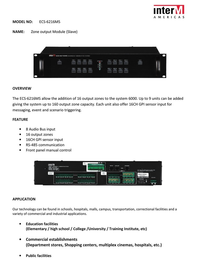
Inter-m ECS-6216MS Installation guide

Inter-m

Inter-m ECS-6216MS Installation guide

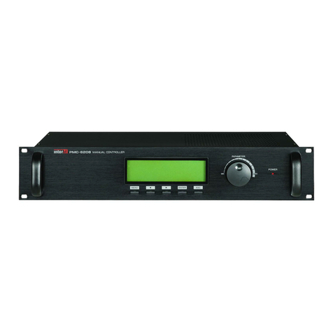
Inter-m PMC-6208 User manual

Inter-m

Inter-m PMC-6208 User manual

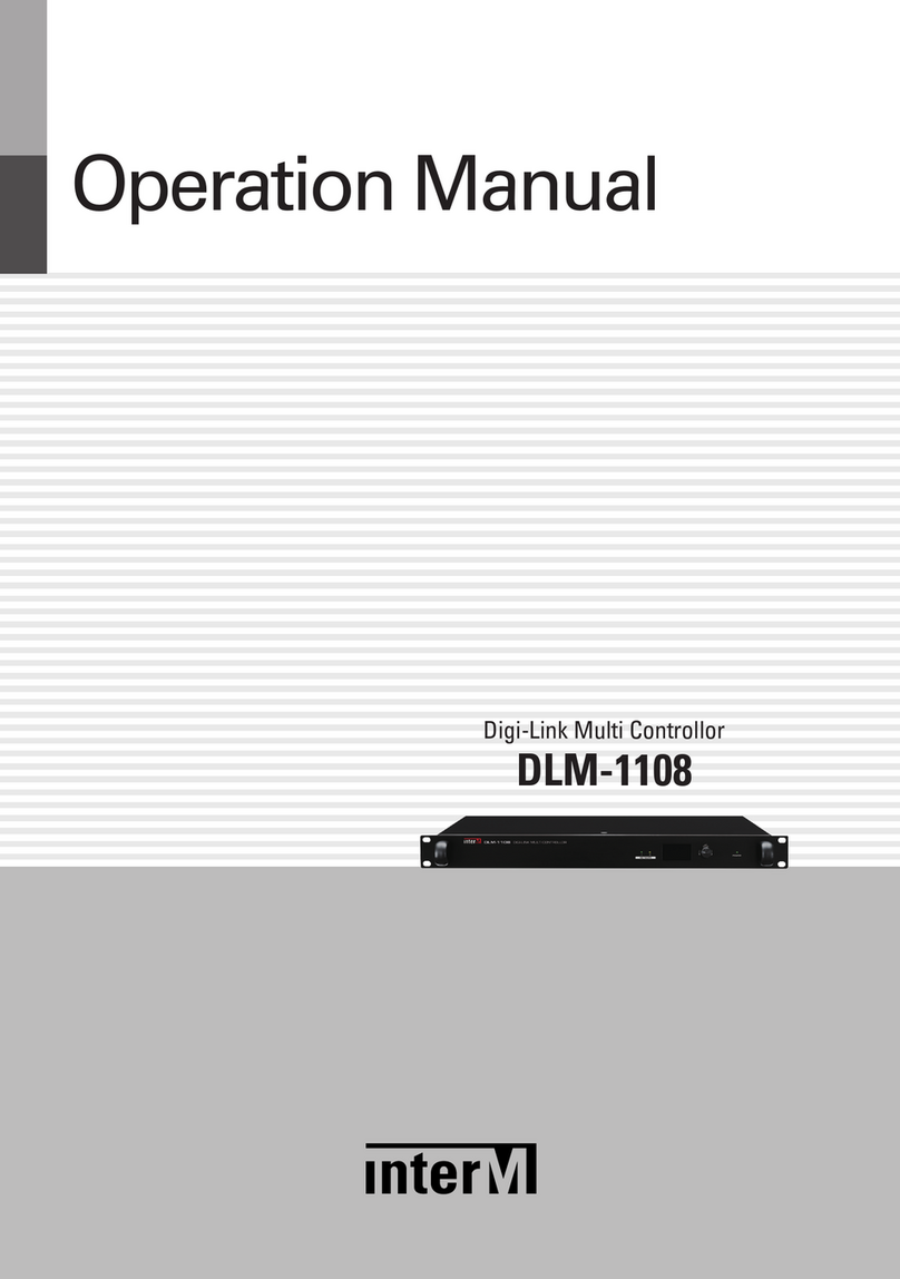
Inter-m DLM-1108 User manual

Inter-m

Inter-m DLM-1108 User manual

Inter-m IPA-100 User manual

Inter-m

Inter-m IPA-100 User manual

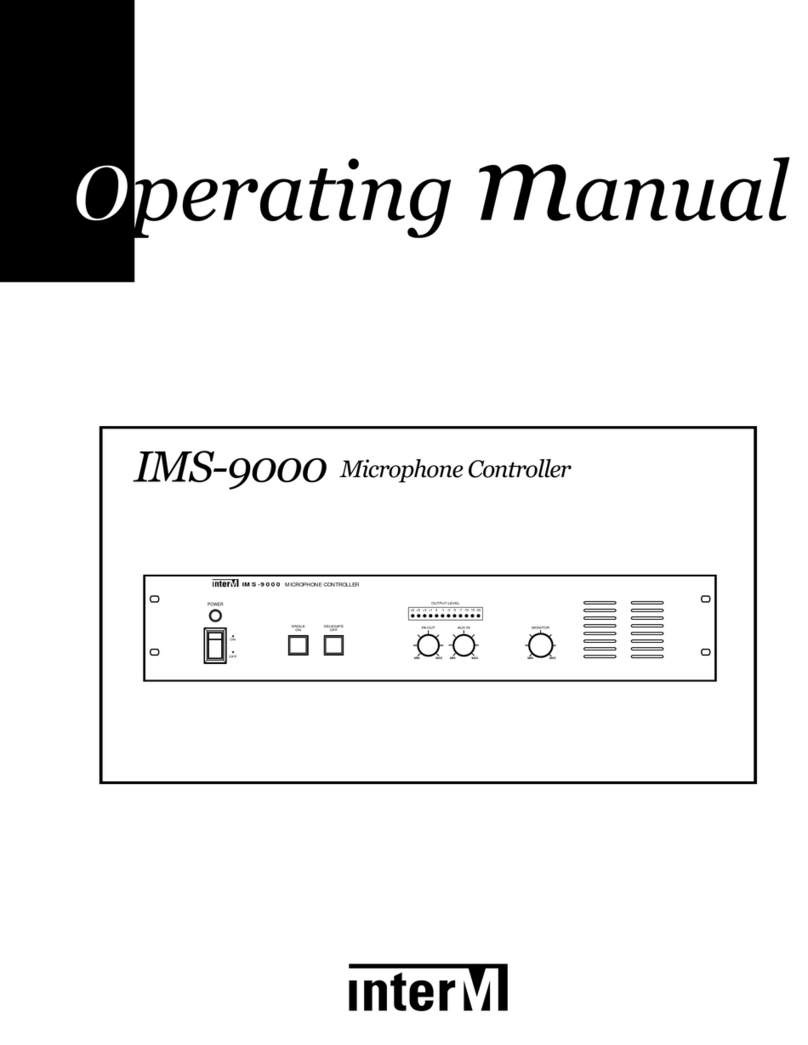
Inter-m IMS-9000 User manual

Inter-m

Inter-m IMS-9000 User manual

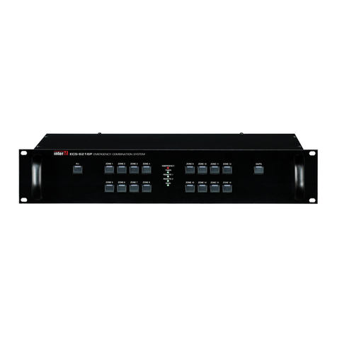
Inter-m ECS-6216P User manual

Inter-m

Inter-m ECS-6216P User manual

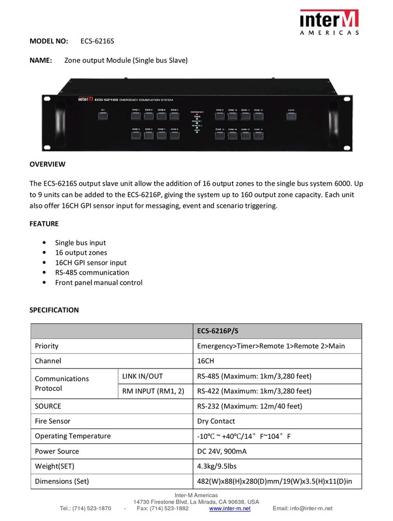
Inter-m ECS-6216S Installation guide

Inter-m

Inter-m ECS-6216S Installation guide

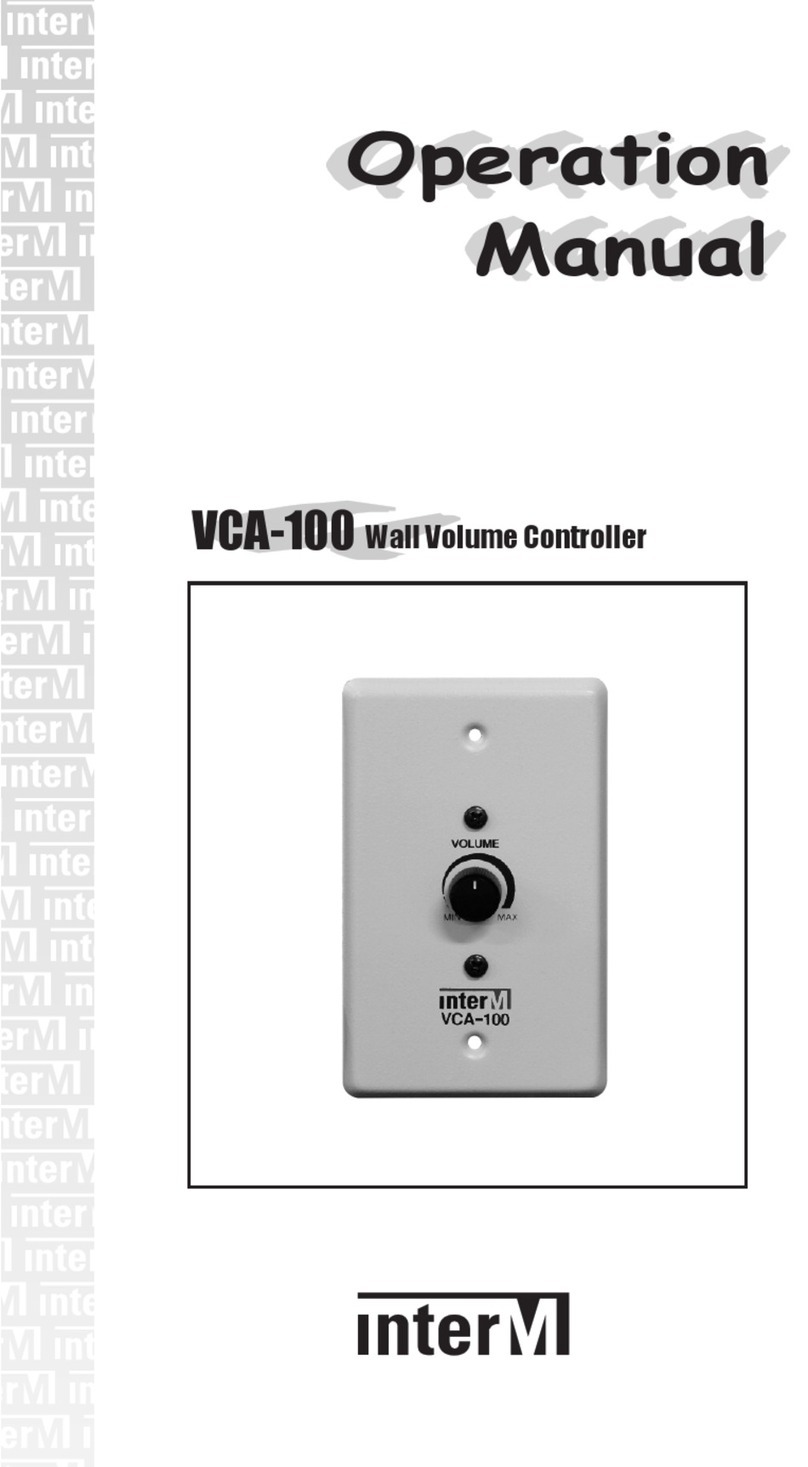
Inter-m VCA-100 User manual

Inter-m

Inter-m VCA-100 User manual

Popular Controllers manuals by other brands

Wunda WundaSmart user guide

Wunda

Wunda WundaSmart user guide

Fisher FIELDVUE DVC6200 HW1 instruction manual

Fisher

Fisher FIELDVUE DVC6200 HW1 instruction manual

XTS Video XTS-KBC-100 user manual

XTS Video

XTS Video XTS-KBC-100 user manual

GSI Group PNEG-1813 Installation and operation manual

GSI Group

GSI Group PNEG-1813 Installation and operation manual

AirStage UTY-RNKY installation manual

AirStage

AirStage UTY-RNKY installation manual

Powered Aire AERO CONNECT Operating and maintenance manual

Powered Aire

Powered Aire AERO CONNECT Operating and maintenance manual

Mitsubishi Electric RD77MS2 user manual

Mitsubishi Electric

Mitsubishi Electric RD77MS2 user manual

Vibration Research VR9500 Hardware manual

Vibration Research

Vibration Research VR9500 Hardware manual

Synapse DIM10-250-11 installation guide

Synapse

Synapse DIM10-250-11 installation guide

BFT ARES Installation and user manual

BFT

BFT ARES Installation and user manual

Emerson Fisher 92S instruction manual

Emerson

Emerson Fisher 92S instruction manual

SCHUNK PGN-plus-P 64 Assembly and operating manual

SCHUNK

SCHUNK PGN-plus-P 64 Assembly and operating manual

Carel pCO Series Application program

Carel

Carel pCO Series Application program

Axis 295 Specifications

Axis

Axis 295 Specifications

RMT DX5100 Technical manual

RMT

RMT DX5100 Technical manual

Turnigy AE-20A user manual

Turnigy

Turnigy AE-20A user manual

ISSI IS31IO8972 EVB user guide

ISSI

ISSI IS31IO8972 EVB user guide

TERMOFOL Mark II TF-H2 operating manual

TERMOFOL

TERMOFOL Mark II TF-H2 operating manual

manuals.online logo
manuals.online logoBrands
  • About & Mission
  • Contact us
  • Privacy Policy
  • Terms and Conditions

Copyright 2025 Manuals.Online. All Rights Reserved.