Focal Solo6 Be User manual

SOLO6 BE - TWIN6 BE - SUB6
取扱説明書 /
Manuel d’utilisation / User Manual / Gebrauchsanleitung/
Manuale d’uso / Manual de uso / Manual de utilização /
Handleiding / Instrukcja obsługi / Руководство по
эксплуатации / 使用手册 / 사용 설명서 /
FR EN

4
EN
SOLO6 BE : SPECIFICATIONS
User manual
SYSTEM
Frequency response 40Hz - 40kHz
Maximum SPL 113dB SPL (peak @ 1m)
ELECTRONIC SECTION
Input Type/Impedance
Connector
Sensitivity
Electronically balanced / 10 kOhms
XLR
Adjustable, +4dBu ou -10dBV
LF amplifier stage
HF amplifier stage
150W rms, BASH®technology
100W rms, class AB
Power supply Main Voltage
Connection
230V (1.6A fuse rating)
115V (3.15A fuse rating)
IEC inlet and detachable power cord
User controls Input level switch
LF and HF contours (potentiometers)
Power ON/OFF switch, mains voltage selector
Indicator Power on LED
TRANSDUCERS
Woofer "W" cone, Focal 6W4370B 6.5" drive unit
High frequency Focal TB871 inverted Beryllium dome tweeter
with protective grille
Shielding Integral through concellation magnets or by magnet design
CABINET
Construction 19mm MDF panels with internal braces
Finish Real red veneer on sides
Dimensions (HxWxD) 330mm x 240mm x 290mm - (13"x9.5"x11.4")
Weight 11kg - (24.2lb)
All specifications are subject to change.

5
EN
TWIN6 BE : SPECIFICATIONS
User manual
SYSTEM
Frequency response 40Hz - 40kHz
Maximum SPL 115dB SPL (peak @ 1m)
ELECTRONIC SECTION
Input Type/Impedance
Connector
Sensitivity
Electronically balanced / 10 kOhms
XLR
Adjustable, +4dBu ou -10dBV
LF amplifier stage
LF/MF amplifier stage
HF amplifier stage
150W rms, BASH®technology
100W rms, class AB
Power supply Main Voltage
Connection
230V (2A fuse rating)
115V (4A fuse rating)
IEC inlet and detachable power cord
User controls Input level switch
Speaker (left/right) switch
LF and HF contours (potentiometers)
Power ON/OFF switch, mains voltage selector
Indicator Power on LED
TRANSDUCERS
Woofer 2 x "W" cone, Focal 6W4370B 6.5" drive unit
High frequency Focal TB871 inverted Beryllium dome tweeter
with protective grille
Shielding Integral through concellation magnets or by magnet design
CABINET
Construction 19mm MDF panels with internal braces
Finish Real red veneer on sides
Dimensions (HxWxD) 250mm x 500mm x 340mm (9.8" x 19.7"x 13.4")
Weight 14kg - (30.8lb)
All specifications are subject to change.

6
EN
SUB6 : SPECIFICATIONS
User manual
All specifications are subject to change.
SYSTEM
Frequency response 30Hz - 250Hz
Maximum SPL 116dB SPL (peak @ 1m)
ELECTRONIC SECTION
Input Type/Impedance
Connector
Sensitivity
Left, Right, LFE
Electronically balanced / 10kOhms
Female 3 pins XLR
Variable
Output (to satellites) Type/Impedance
Connector
Left, Right
Electronically balanced / 50Ohms
Male 3 pins XLR
Amplifier 350 W rms, BASH®
technology
Internal processing
and functions
Subwoofer section
Satellite section
Left + Right mono summation
LFE + lo-passed mono sum
24dB/octave variable lo-pass filter
Phase adjustment
Polarity
24dB/octave, defeatable hi-pass filters
with selectable frequency
User controls Sub level (sensitivity) adjustment
Lo-pass frequency adjustment
Phase adjustment
Polarity switch
Mute
2.1 bypass (controlled by external footswitch)
Hi-pass frequency selection
Hi-pass defeat
Indicators (LED’s) Power on
Mute
Hi-pass defeat
Power supply Mains voltage
Connection
230V (T1.6AL fuse rating) or 115V (T3.15AL fuse
rating)
IEC inlet and detachable power cord
TRANSDUCERS
Subwoofer “W” composite sandwich cone, high excursion Focal 11W7670,
270mm (10.6”) drive unit
CABINET
Construction 22mm MDF panels with internal braces
Finish Real red veneer on sides - Black on body
Dimensions (HxWxD) 380mm x 344mm x 440mm (15” x 13.5”x 17.3”)
Weight 23kg (50.7lb)
Due to constant technological advances, Focal reserves its right to modify specifications without notice.
Images may not conform exactly to specific product.

SOLO6 BE - TWIN6 BE - SUB6
User manual 7
EN
Thank you for purchasing a Focal product. Welcome to our High-Fidelity world. Innovation, tradition, excellence
and pleasure are our values; our one and only aim is to bring you a sound that is rich, pure and true. To get the
most out of your product, we recommend that you read the instructions in this booklet, then store it in a safe
place to refer to in the future.
Unpacking
In addition to one loudspeaker and a user manual (such as this one), each Solo6 Be or Twin6 Be carton should
contain:
• A power cord.
• A guarantee card.
• A plastic bag containing an information note “Beryllium inverted dome tweeter”, and some adhesive tape to
ax on the tweeter in the unlikely event of the dome being damaged.
In addition to one subwoofer and a user manual each Sub6 Be carton include:
• A power cord.
• A guarantee card.
• A grille protecting the drive unit (which it is advisable to remove whenever possible).
Please check that none of these items are missing, and remove all accessories from the carton.
To remove the loudspeaker from its carton without damage, open the end flaps fully and bend them right
back. Then remove the upper cushion and lift the loudspeaker out gently. Inspect the speaker for signs of any
possible damage.In the unlikely event of this having occurred please inform the carrier and supplier. It is a good
practice to keep the packaging in case of future transportation.
Beryllium
Solo6 Be and Twin6 Be use a tweeter with an inverted dome made from pure beryllium, with the capacity to
augment the bandwidth to 40 kHz. In its solid form, beryllium is harmless. However, given its nature, certain
precautions should be taken to avoid exposure to unnecessary risks:
• The beryllium dome must never come into contact with abrasive materials.
• If the beryllium dome is damaged in any way, you should cover up the entire surface area of the dome using
the protective adhesive strip supplied, as soon as possible. You will find the adhesive strip in the plastic packet
containing the leaflet for the tweeter with an inverted dome made from pure beryllium. Contact the retailer to
have the tweeter dismantled and replaced by trained personnel at the distributor.
• If the dome is broken, any beryllium particles should be carefully collected using sticky tape and then placed
in a hermetically sealed plastic bag and sent back to the retailer along with the loudspeaker.
For more information, please refer to the safe use manual in the box.
You can also address your questions directly to:
beryllium@focal.com
Conditions of warranty
All Focal loudspeakers are covered by warranty drawn up by the official Focal distributor in your country. Your
distributor can provide all details concerning the conditions of warranty. Warranty cover extends at least to
that granted by the legal warranty in force in the country where the original purchase invoice was issued.
Please validate your Focal-JMlab warranty,
it is now possible to register your product online: www.focal.com/warranty

SOLO6 BE - TWIN6 BE - SUB6
User manual 8
EN
Input
sensitivity switch
D
B
Midrange
Midrange
E
A
Audio
input connector
Voltage selector Fuse holder
HF control
LF control
Audio
input connector
Input sensitivity
Switch
Midrange driver
selector Voltage selector
Fuse holder
HF control
LF control
Position A
Left/Right
Position B
Left/Right
Position C
Left
Position C
Right
Position A
Left/Right
Position B
Left
Position C
Left Right
Driver choosen to reproduce midrange when switch selected for left speaker
Driver choosen to reproduce midrange when switch selected for right speaker
Left/Right
Right
F
C
Recommended choice for
midrange driver positionning.
Midrange driver on the inside.

SOLO6 BE - TWIN6 BE - SUB6
User manual 9
EN
Hi Pass switch
Defeat switch
Phase control
Level control
Lo Pass control
Polarity switch
Mute switch
Voltage selector
Audio intput connectors
(Stereo/2.1 wiring only)
Audio output connectors
to satellites speakers
(Stereo/2.1 wiring only)
LFE input connector
(mutichannel
wiring only)
G
6.35 Jack connector
for 2.1 Bypass
footswitch
remote control

SOLO6 BE - TWIN6 BE - SUB6
User manual 10
EN
Solo6 Be
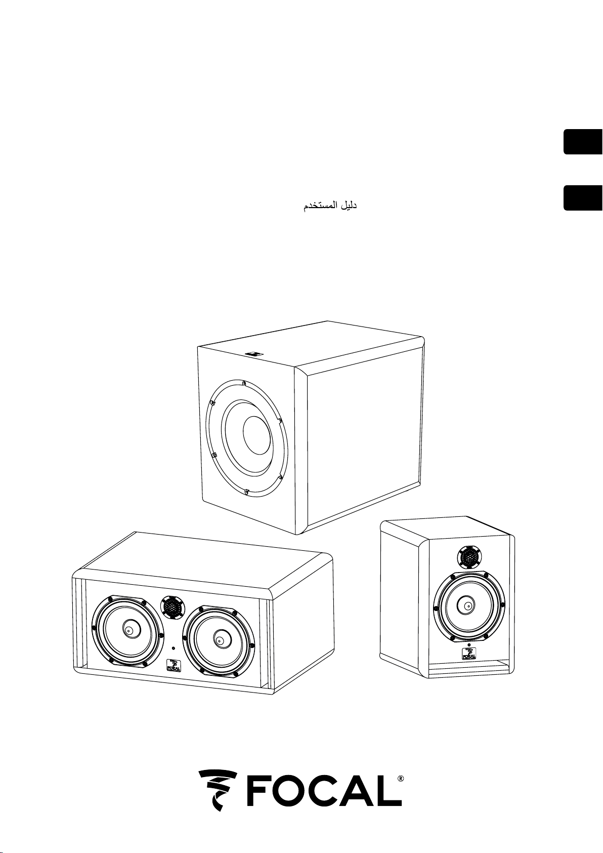
Solo6 Be is a two-way active loudspeaker (2 internal amplifiers channels), comprising one “W” cone 6.5” low/
mid unit, loaded with a large cross-section laminar port, and an inverted pure Beryllium dome (fig. A).
Twin6 Be
Twin6 Be is a three-way active loudspeaker (3 internal amplifiers channels), comprising two “W” cone 6.5” low/
mid units, loaded with two large cross-section laminar ports, and an inverted pure Beryllium dome. The two
6.5” drive units operate at low frequencies but only one of them (either can be selected) will reproduce the
midrange (fig. B).
Sub6
Sub6 is an active subwoofer (1 integral amplifier) designed for professional monitoring systems. It uses a 11”
drive unit equipped with a “W” composite cone, and loaded by a large cross-section laminar port (fig. G).
Sub6 may be used :
- For bass or sub-bass enhancement in stereo + sub setups (2.1 or 2.2). The rear panel of Sub6 allows for the
connection of a traditional stereo source (Left In / Right In), while providing hi-passed outputs intended to
feed the main speakers (satellites),
- As a LFE channel (Low Frequency Eects) in a multi-channel installation (5.1, 5.2, 6.1…), via a dedicated input
of the rear panel.
Installing
Mains voltage
After having unpacked the unit, first check that the operating voltage is correctly set (see location on rear
panel). If it is not, adjust the selector to the appropriate position. Also check and if necessary replace the fuse,
which rating depends on the operating voltage (please refer to technical specifications).
Solo6 and Twin6 must be earthed using the power cord supplied.
Audio connections: general
The audio signal is to connect to the XLR inlet. This is a balanced input, which use the standard cabling scheme,
namely:
Pin 1 = Ground (shield)
Pin 2 = In phase voltage (“hot”)
Pin 3 = Out-of-phase voltage (“cold”)
If the audio source is unbalanced, common practice is to link “cold” and ground pins (pins 3 and 1 respectively).
This is generally achieved within the cable.
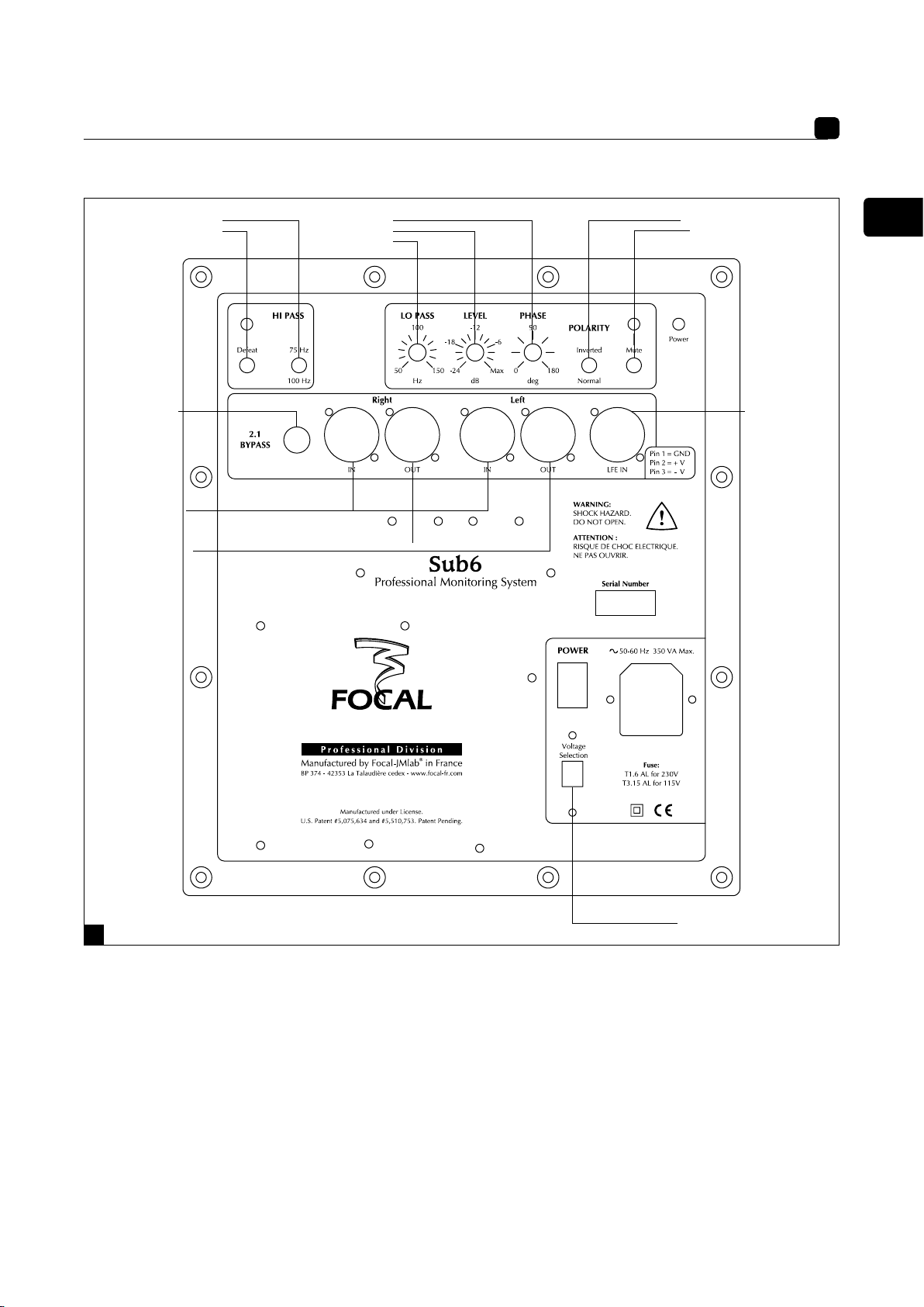
Audio connections: Sub6 (fig. G)
Stereo + Sub setup (2.1 or 2.2):
Left IN: this input is intented to receive the signal coming from the left channel of your source (mixing console,
or other…).
Right IN: this input is intented to receive the signal coming from the right channel of your source (mixing
console, or other…).
Left OUT:this output is intended to connect to the left main loudspeaker of your system. The signal supplied
by this output is internally processed through a high pass filter.
Right OUT: this output is intended to connect to the right main loudspeaker of your system. The signal supplied
by this output is internally processed through a high pass filter.
Multichannel configuration: LFE: this input is intended to feed your Sub6 in a multichannel application (5.1, 5.2,
6.1, …): this channel is dedicated to low frequencies only.

SOLO6 BE - TWIN6 BE - SUB6
User manual 11
EN
Positioning
Solo6 Be and Twin6 Be are designed for near field monitoring and should be placed at a distance between 1
and 3 metres from the listener, pointing towards the listening position. They can be sitting on the console top
or placed on appropriate stands. In any way it is recommended that the tweeter is at a height from the floor
approximately equivalent to that of the listener’s ears. If required it can make sense to place the speakers
upside down so that the previous rule is better fulfilled (fig. C,D).
Solo6 Be could be used vertically or horizontally depending on the environment, preferably pointing towards
the listener (fig. C).
By design Twin6 Be’s are rather intended for a landcape orientation, though in some situations they could be
positioned vertically. As seen in the earlier rear panel description, Twin6 Be has a switch allowing to choose
which drive unit is to reproduce the mid frequencies (see below) (fig. E). Consequently it will always be
possible, as desirable, to configure the speakers in a “mirror” (ie symetrical) way (fig. F). As a general rule
having the “midrange” driver on the inside of the cabinet results in better imaging.
Optimal positioning of Sub6 may vary depending on the surface, the shape and acoustic properties of the
listening room. You are advised to try various locations so to choose the one giving the best possible and most
level sound balance. As a rule of thumb the optimal location will often be in a corner of the room.

SOLO6 BE - TWIN6 BE - SUB6
User manual 12
EN
Running in
As in all brand new loudspeaker the drivers need some run in period: they are mechanical elements demanding
a little time to settle and adapt to the climatic environment. This period will vary depending of the working
conditions and may take up to a few weeks. Avoid pushing the speakers very hard during their first hours of
use, but to accelerate the run-in process it is good practice to operate the speakers at moderate levels for 20
hours or so, with programmes having significant low frequency content. Only once the transducers have come
to stabilize will you get the optimum performance.
Solo6 Be/Twin6 Be/Sub6 Controls
Speaker switch (Left/Right) : only for Twin6 Be
This switch allows the user to select which one of the two 6.5” drivers will reproduce the midrange. By
convention, the “Right” position of the switch will select the left hand side driver (when facing the cabinet
laying horizontally). Conversely in the “Left” position the right hand side driver (facing the cabinet) will be the
one operating in the mid frequencies. It is easy to figure how useful this control is when it comes to get the
best possible imaging in any cabinet layout (fig. E,F).
Input switch
The input sensitivity can be adjusted using this two position switch. The +4dBu position is suitable for standard
professional audio equipment, while -10dBV position may be used for other types of sources providing a lesser
output level.
HF contour
This control allows for a continuous adjustement of the high frequency level; it operates above 5kHz within a
±3dB range (fig. H).
LF contour
This control allows for a continuous adjustement of the low frequency level; it operates below 150Hz within
a ±6dB range (fig. I). This adjustement is typically useful to deal with possible excessive level of LF energy
resulting from acoustic coupling associated with close reflecting surfaces: mixing console, nearby walls…
Power on indicator
A power on LED is located on the cabinet front panel, near the Focal logo.
HI

SOLO6 BE - TWIN6 BE - SUB6
User manual 13
EN
Sub6 controls (fig. G)
Level
This adjustement allows to set the sound level of the subwoofer relative to that of the main loudspeakers. It should
also be optimised taking into account the actual location of the subwoofer and its acoustic consequences: for
example in an angle the 6 dB acoustic gain should be compensated by an equivalent attenuation to maintain
the overall balance of the system.
Mute
This switch will turn out the output signal of the subwoofer channel (making it silent does not require to switch
the power off). When muting the subwoofer the high pass filters used for the main speakers will remain active.
Hi Pass
This area is dedicated to the setting of the high pass filters intended for the main speakers in a 2.1 configuration.
The “Defeat” switch allows to disable (ie by-pass) these filters. The 75 Hz / 100 Hz switch allows to select the
cut-off frequency, in order to optimise the acoustic recombination between the satellites and Sub6.
Lo Pass
This potentiometer adjusts the cut-off frequency of the low pass filter on the subwoofer channel, thus setting
the upper frequency range to be reproduced by Sub6. The goal is to achieve the smoothest frequency response
of the whole system: sub + satellites.
Polarity
This switch inverts the signal polarity on the subwoofer channel (ie 180° phase shift).
Phase
This potentiomer provides some fine ajustment of the phase on the subwoofer channel. Combined with the
polarity switch it can be used to compensate for the spacing between the sub and the main speakers, so to get
a coherent soundfield through a proper time alignment of the different sources.
2.1 Bypass
This input allows for plugging in a control footswitch (not supplied) via a ¼” jack connector.
Turning it active will :
- mute the subwoofer channel
- defeat the high pass filters in the satellites signal paths. The satellites will then be fed with full range signals.
This facility allows for instantaneous comparison between the 2.1 configuration (with sub) and the traditional
stereo setup (without sub) with the same system.
Power indicator
Power "LED" indicator.
Other manuals for Solo6 Be
5
Table of contents
Other Focal Speakers manuals

Focal
Focal Sib User manual

Focal
Focal Sib XL User manual

Focal
Focal CMS 50 - User manual

Focal
Focal 100 ICW 5 User manual

Focal
Focal 1000 IC LCR5 User manual

Focal
Focal 300 SERIES User manual

Focal
Focal DIVA UTOPIA BE User manual

Focal
Focal Sib XL Guide

Focal
Focal BIRD pack 2.1 User manual

Focal
Focal ELITE K2 POWER User manual

Focal
Focal Sib User manual

Focal
Focal SHAPE User manual

Focal
Focal Polyglass 130 VR User manual

Focal
Focal CMS 40 User manual

Focal
Focal SCU - STAND CENTER UTOPIA BE User manual

Focal
Focal ON WALL 300 Instruction Manual

Focal
Focal KANTA N1 User manual

Focal
Focal AUDITOR ACX 100 User manual

Focal
Focal PS 165F User manual

Focal
Focal CHORUS 706 WHITE (X2) User manual