FOCALSPEC LCI1220 User manual

FOCALSPEC LINE CONFOCAL SENSORS
LCI1220 & LCI1620
USER GUIDE
Version 1.0

2019-09-30 FOCALSPEC User quide LCI1220-1620 v1.0 1/31
FocalSpec Oy • Elektroniikkatie 13, FI-90590 Oulu • www.focalspec.com
Version history
Version
Status
Date
Author
Comments
1.0
Approved
30.9.2019
Esa Kalistaja
First version

2019-09-30 FOCALSPEC User quide LCI1220-1620 v1.0 2/31
FocalSpec Oy • Elektroniikkatie 13, FI-90590 Oulu • www.focalspec.com
CONTENTS
0
FOCALSPEC LINE CONFOCAL SENSORS LCI1220 & LCI1620 0
0
1 About this Document..........................................................................................3
2 Safety Information ............................................................................................3
2.1 Safety Notes 3
2.2 Warnings 3
2.3 Proper Use 4
2.4 CE Marking 4
3 Technical Data...................................................................................................5
4 Delivery Contents ..............................................................................................5
5 Connecting to PC...............................................................................................6
6 Installation and Mounting...................................................................................6
7 Handling Optical Cable and SFP+ Modules ..........................................................9
7.1 General Instructions 9
7.2 Installing SFP+ Module and Optical Cable 10
7.3 Detaching SFP+ Module from Optical Cable 11
8 Electrical Connections..................................................................................... 12
9 Input and Output Description ........................................................................... 15
10 External Trigger Configurations......................................................................20
11 Sensor Warming Up ........................................................................................ 21
12 Preparing Measurement Setup ....................................................................... 21
13 Getting Started ..............................................................................................23
14 Troubleshooting.............................................................................................29
15 Support..........................................................................................................30
16 Abbreviations.................................................................................................30

2019-09-30 FOCALSPEC User quide LCI1220-1620 v1.0 3/31
FocalSpec Oy • Elektroniikkatie 13, FI-90590 Oulu • www.focalspec.com
1About this Document
This document is user guide of sensors LCI1220 and LCI1620. Sensors LCI401, LCI1200,
LCI1201 and LCI1600 are covered by separate guide. FocalSpec Software Development
Kit (FSSDK) and the API documentation can be found after FSSDK installation from
folder: C:\Focalspec\FocalSpec Software Development Kit\Manual.
2Safety Information
This chapter contains important safety information for installing and using the LCI
sensors.
•Note! Read this document carefully before use.
•Note! Keep this document for future reference.
•Note! Original instructions. The original language is English.
2.1 Safety Notes
This document uses safety notes as follows:
•Note! Notes are tips, shortcuts or alternative approaches to the task at hand.
Ignoring a note should have no negative consequences.
•Caution! A Caution statement alerts you to situations that can be potentially
hazardous to you or cause damage to hardware, firmware, software, or data.
•Warning! A Warning statement indicates conditions or situations that can be
potentially lethal or extremely hazardous to you. Safety labels are also attached
directly to products to warn of these conditions or situations.
2.2 Warnings
•Caution! Do not remove any safety devices or open the cover. Risk of injuries
and insecure operation. The warranty is void if the cover is opened.
•Caution! Do not look directly into the light source. Light radiation may damage
your eyes.
•Caution! This is a high-precision optical instrument. Protect the device from
dust and moisture and avoid subjecting it to shocks and strong forces.
•Caution! Before using the sensor for the first time, check the sensor for
transport damage. If the sensor is damaged, contact support. See
Support
.
•Warning! Use only qualified personnel for the installation of all electrical
supplies and fixtures, and make sure that all installations adhere to local
regulations and safety standards.

2019-09-30 FOCALSPEC User quide LCI1220-1620 v1.0 4/31
FocalSpec Oy • Elektroniikkatie 13, FI-90590 Oulu • www.focalspec.com
2.3 Proper Use
The LCI sensor is designed for the use in industrial areas. The sensor is used for optical
measurements, such as 3D topography, dimensions and distances measurements,
measuring the tomography of transparent materials, surface micro profile
measurements, and film thickness measurements.
Only use the sensor in such a way that, in the case of malfunction or failure, personnel
or machinery are not endangered.
Ambient temperature range: +15 ºC … +35 ºC.
2.4 CE Marking
FocalSpec Oy has confirmed that these products comply with the essential
requirements of the applicable EC Directive, based on the following specifications.

2019-09-30 FOCALSPEC User quide LCI1220-1620 v1.0 5/31
FocalSpec Oy • Elektroniikkatie 13, FI-90590 Oulu • www.focalspec.com
3Technical Data
Table 1. Technical data for the sensors
LCI 1220
LCI 1620
Optical profile length
11.6
17.0
mm
Pixel size X
6.7
9.85
µm
Pixel size Y
10
36
µm
Z repeatability*
0.19
0.25
µm
Stand-off distance
20.58
64.00
mm
Depth of field
3.00
5.50
mm
Measurement speed at full depth of
field
3000
3000
Hz
Max measurement speed**
16000
11000
Hz
Number of points / profiles
1728
1728
Max slope of objects +/-
20.0
13.5
deg
Dimensions
419x354x91
432x358x113
mm
Weight
19
21
kg
Level of protection (EN 80529)
IP55
IP30
* Z repeatability is the standard deviation of Z measurements using the FocalSpec target at the specified
reference distance
** Maximum speed is maximum frequency to measure region of interest (ROI) with the depth 0.4 mm on full
optical profile length
4Delivery Contents
Sensor delivery content includes:
✓FocalSpec LCI sensor
✓PushPull type 4-pin power cable (5 m)
✓PushPull type 10-pin signal cable (5 m)
✓Push Pull type optical cable (5 m) with two SFP+ modules
✓USB drive:
oSoftware Development Kit (FSSDK) installer
oLCI1220 and 1620 user guide
oSensor 3D CAD STEP files
oSensor mounting drawings
Reference measurement sample is an optional sales item, and not included in the
standard delivery content.
2019-09-30 FOCALSPEC User quide LCI1220-1620 v1.0 6/31
FocalSpec Oy • Elektroniikkatie 13, FI-90590 Oulu • www.focalspec.com
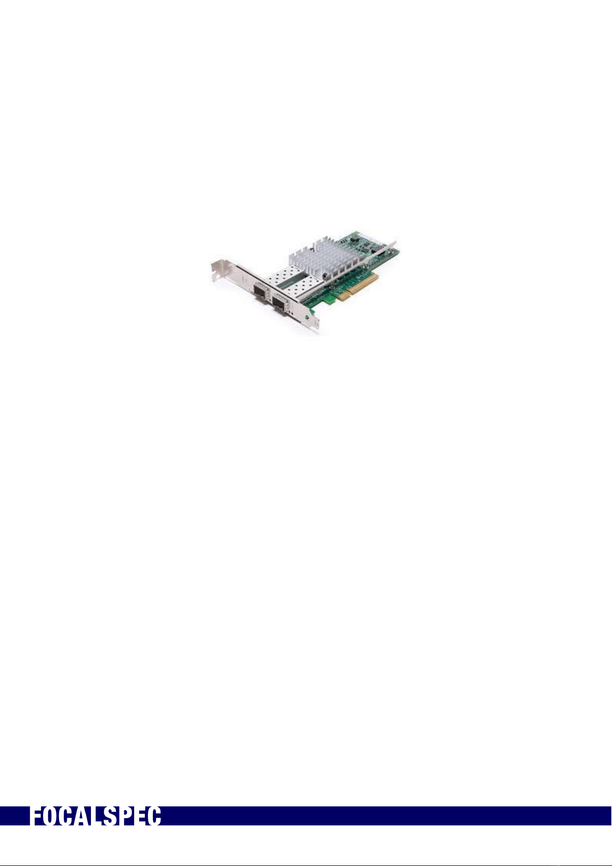
5Connecting to PC
10 Gbit connection with SFP+ interface is needed to enable the high-speed data
transmission.
The recommended network adapter is Intel Ethernet Converged Network Adapter X520
either two port DA2 or four port DA4 model.
Figure 1. Example of two port Intel Ethernet Converged Network Adapter X520 DA2
Windows 10 64-bit is the recommended operating systems, but sensors work also with
Windows 7.
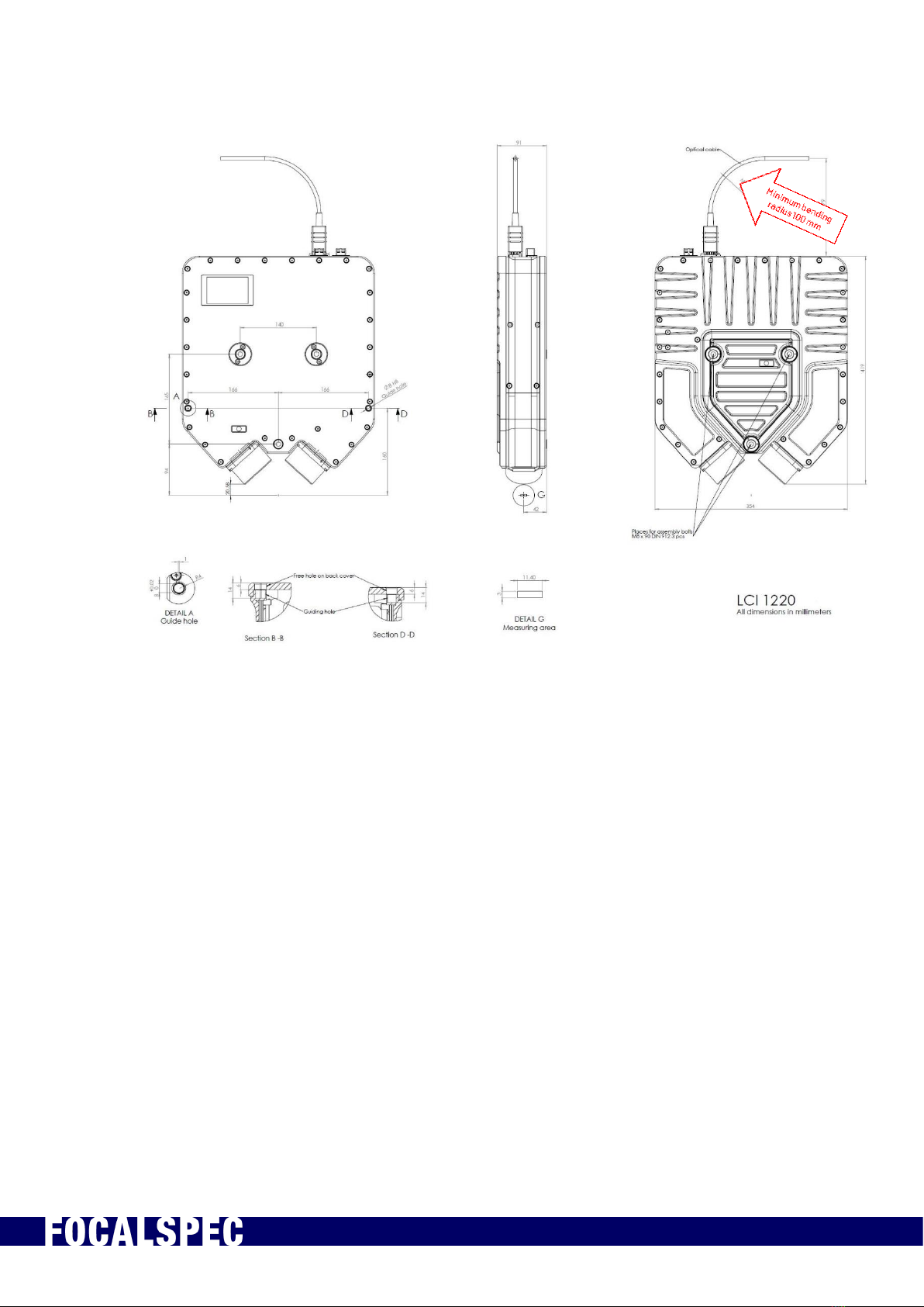
6Installation and Mounting
3D CAD STEP as well as high-resolution versions of the drawings below are included in
the USB drive folder “hardware”. The position and orientation of the optical profile is
shown in an enlarged detail image for each model. The X, Y, Z origin in each STEP file is
placed into the middle of the optical profile.
2019-09-30 FOCALSPEC User quide LCI1220-1620 v1.0 7/31
FocalSpec Oy • Elektroniikkatie 13, FI-90590 Oulu • www.focalspec.com
Figure 2. Installation and mounting of LCI1220.
2019-09-30 FOCALSPEC User quide LCI1220-1620 v1.0 8/31
FocalSpec Oy • Elektroniikkatie 13, FI-90590 Oulu • www.focalspec.com
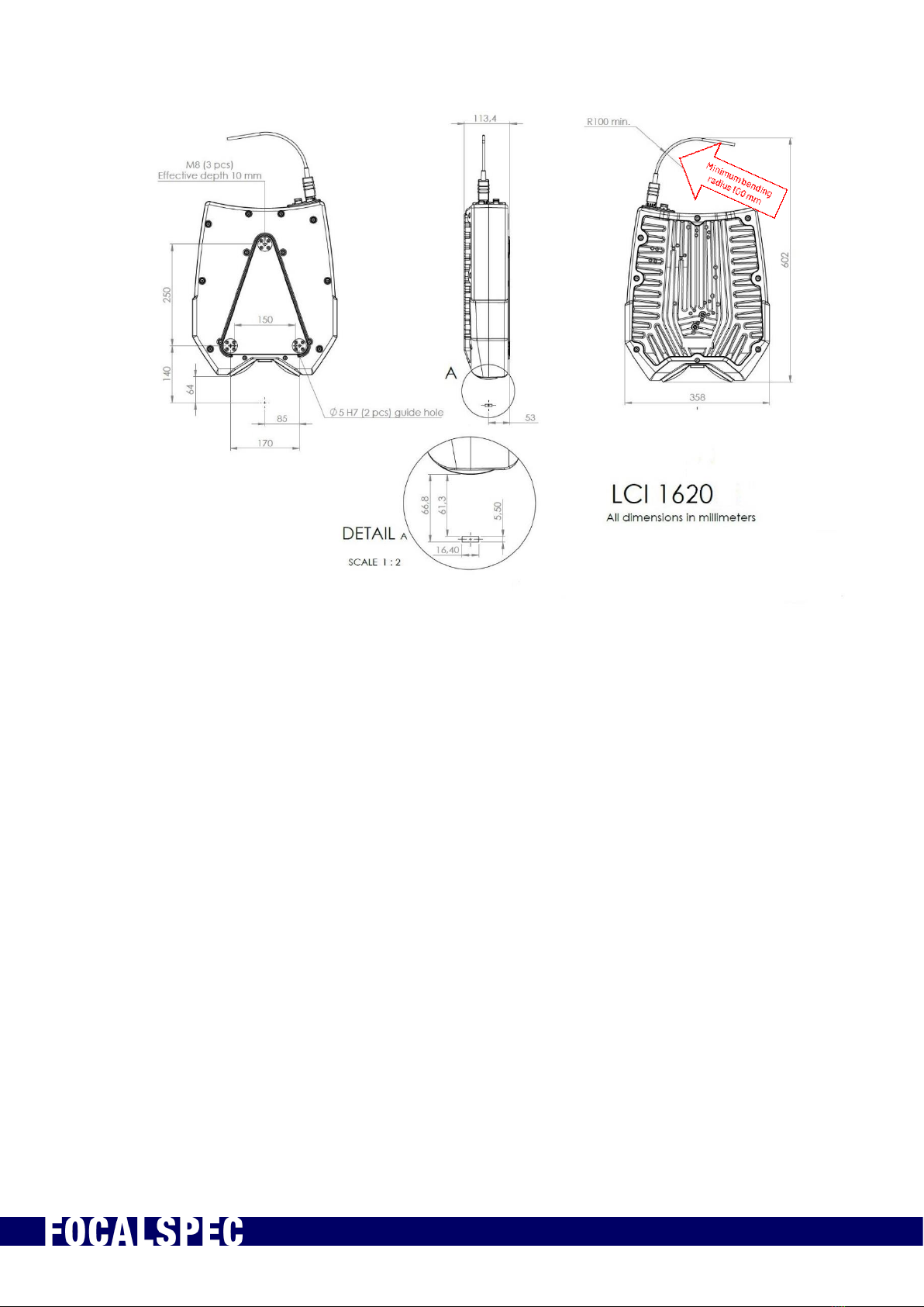
Figure 3. Installation and mounting of LCI1620.

2019-09-30 FOCALSPEC User quide LCI1220-1620 v1.0 9/31
FocalSpec Oy • Elektroniikkatie 13, FI-90590 Oulu • www.focalspec.com
7Handling Optical Cable and SFP+ Modules
IMPORTANT – FRAGILE
Minimum bending radius of optical cable is 100 mm. Don’t bend
cable more than this. This applies to the whole length of the
cable and it is especially important to pay attention to computer
end of the cable as it is more flexible.
Never touch optical cable fiber ends with bare hands or let the
fiber ends touch anything else but cleaning equipment.
Never put anything inside the optical fiber slots of the SFP+
module.
7.1 General Instructions
1. When storing optical cables and SFP+ modules, make sure the protective caps are
attached.
2. When the cables and SFP+ modules are in use, store the protective caps in an
airtight plastic bag.
3. Never touch the cable ends with anything other than the cleaning cloth.
4. If a cleanroom is available, it’s recommended to install SFP+ modules to cable in
there.
5. Preferably wear cloth gloves when handling cable connectors.
6. Make sure the minimum bending radius of cable bend is about 100 mm (Figure 3).
Don’t let the cable bend more than this. This applies to the whole length of the cable
and it is especially important to pay attention to computer end of the cable as it is
more flexible.

2019-09-30 FOCALSPEC User quide LCI1220-1620 v1.0 10/31
FocalSpec Oy • Elektroniikkatie 13, FI-90590 Oulu • www.focalspec.com
Figure 4: Minimum bending radius of the optical cable is 100 mm
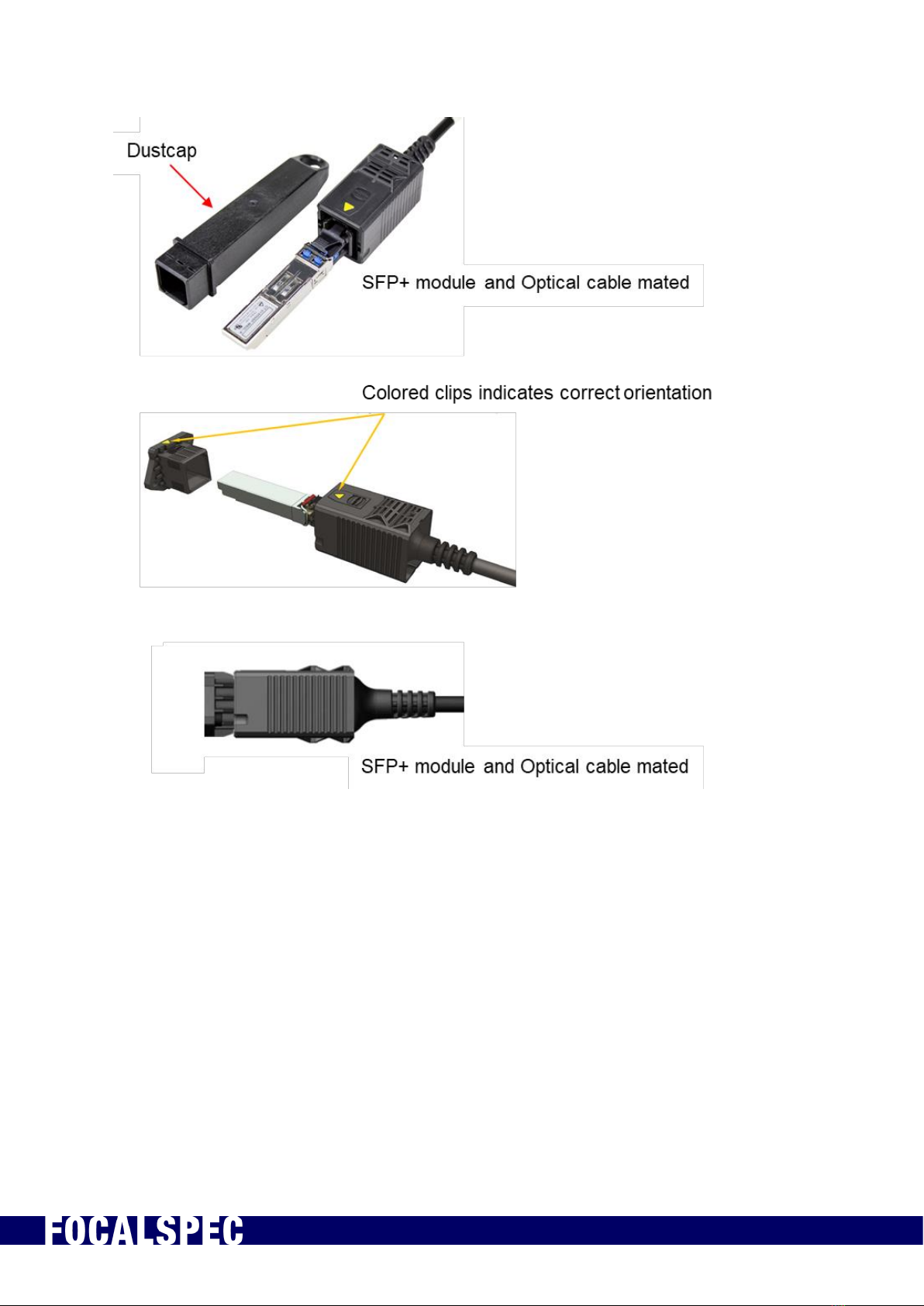
7.2 Installing SFP+ Module and Optical Cable
Steps to install the optical cable and SFP+ module:
1. Remove protective plug from SFP+ module.
2. Remove protective caps from the other end of the optical cable. Be sure not to touch
the optical fiber ends with anything.
3. Push the lock handle down on the SFP+ module (step 1). This is the open position.
This is done because the SFP+ module might be used with some SFP+ slots which
.
2019-09-30 FOCALSPEC User quide LCI1220-1620 v1.0 11/31
FocalSpec Oy • Elektroniikkatie 13, FI-90590 Oulu • www.focalspec.com
have a lock. Having the lock readily in the open position enables quick and easy
attaching of the SFP+ module.
4. Carefully insert the cable connector to SFP+ module. Push the connector gently until
it locks in place (step 2). Usually there is an audible “click” when the connector locks
in place. Make sure the lock handle has remained in the open position.
5. Verify that connector is locked to the SFP+ module by pulling very gently on the
cable: it must not be loose (step 3). If it is loose and detaches from the SFP+ module,
repeat by pushing the connector to the SFP+ module until it locks into place.
6. Insert SFP+ module to the SFP+ card at PC (step 4). Make sure the SFP+ module is
positioned in the correct way.
◦CORRECT: There should be a slight resistance when pushing the SFP+ module
the correct way, as the connector in the SFP+ module slides into the connector at
SFP+ slot side. The SFP+ module should not come out very easily.
◦INCORRECT: If the SFP+ module is inserted in incorrect way, there is no
resistance. The SFP+ module slides out very easily.
7. Insert the quick connector of the optical cable to the sensor.
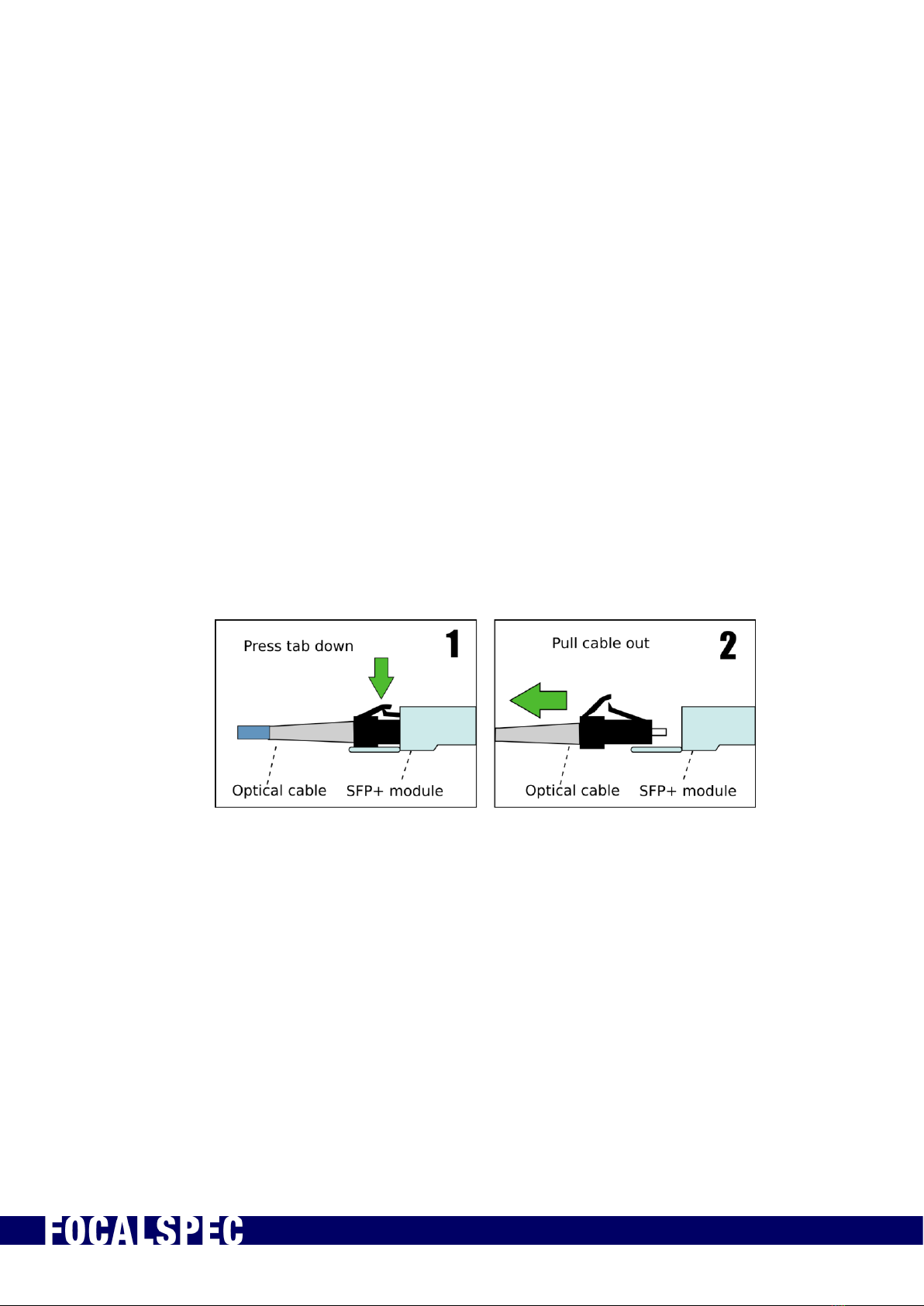
7.3 Detaching SFP+ Module from Optical Cable
Steps to detach SFP+ module from optical cable:
1. Press the lock tab down in optical cable connector (step 1).
2. Pull the cable out of SFP+ module (step 2).
3. Place protective caps on the optical cable connector and SFP+ module.
2019-09-30 FOCALSPEC User quide LCI1220-1620 v1.0 12/31
FocalSpec Oy • Elektroniikkatie 13, FI-90590 Oulu • www.focalspec.com
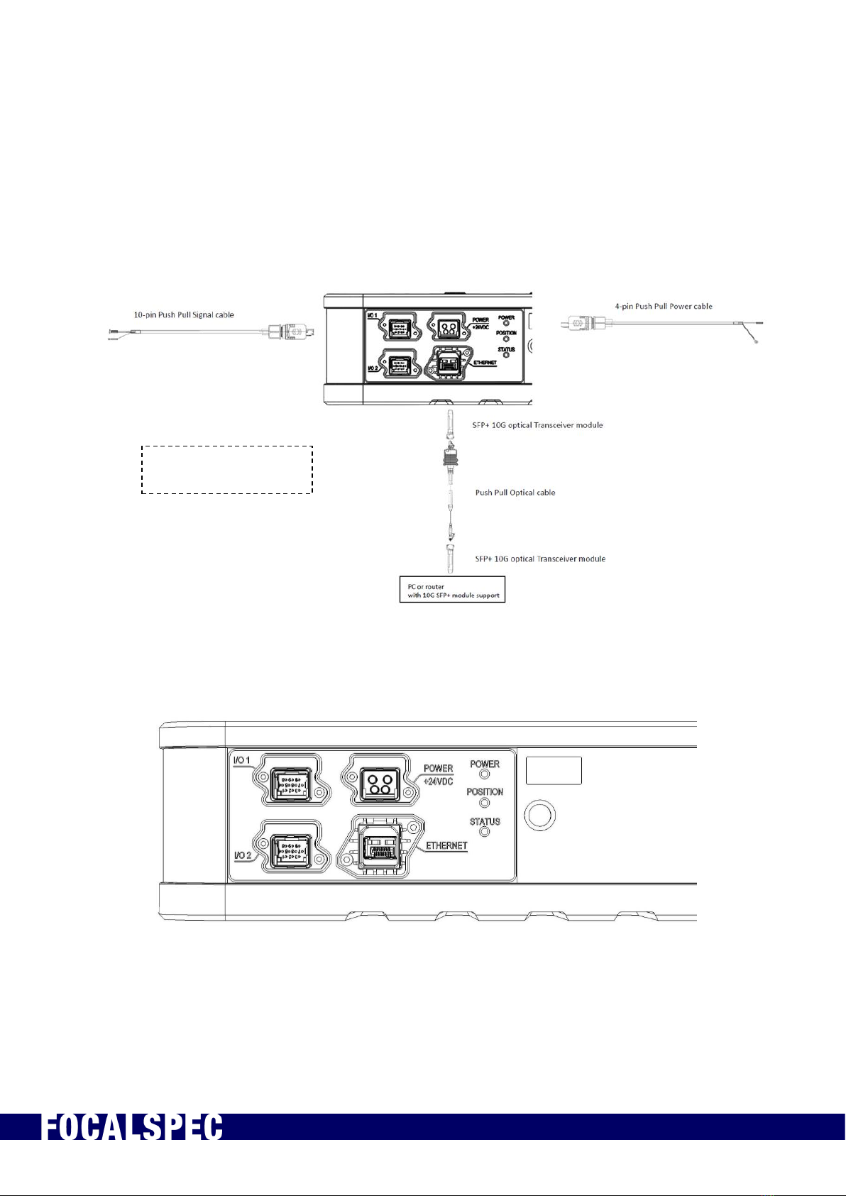
8Electrical Connections
LCI1220 and LCI1620 sensors are powered by using a PushPull type 4-pin cable with
Harting Power connector. For input signals which can be used for synchronization
purposes 10-pin PushPull type cables with Harting Signal Connectors is used. The
sensor communicates with PC via Optical cable with SFP+ 10G transceiver modules.
Figure 5. Electrical connections
Figure 6. Electrical connections for LCI1220 (I/O 2 connector is not in-use at the
moment)
I/O 2 connector is not
in-use at the moment
2019-09-30 FOCALSPEC User quide LCI1220-1620 v1.0 13/31
FocalSpec Oy • Elektroniikkatie 13, FI-90590 Oulu • www.focalspec.com
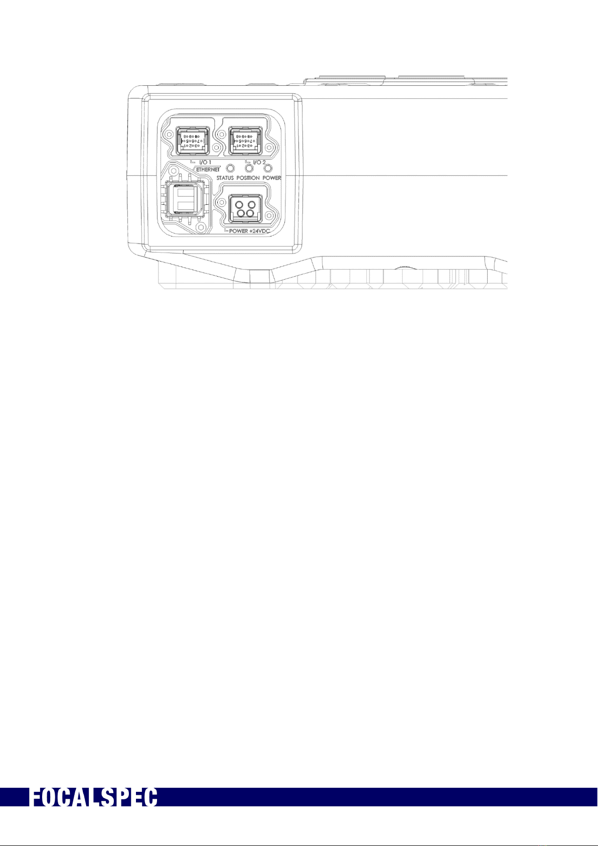
Figure 7. Electrical connections for LCI1620 (I/O 2 connector is not in-use at the
moment)
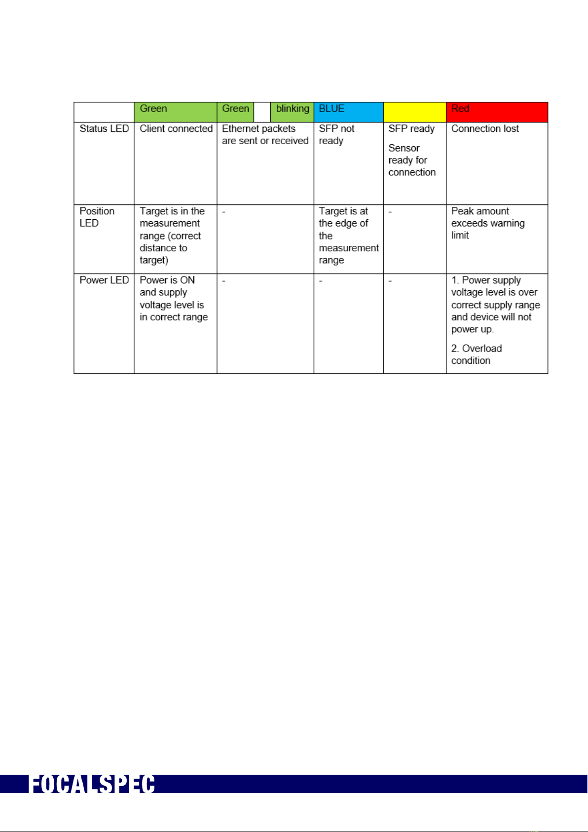
There are three indicator LEDs next to the connectors on the connector panel.
The status LED turns red if the sensor is not connected to a PC or a router. Blue means
SW is booting up, whereas a green light indicates that the connection is established. The
status LED blinks green when Ethernet packets are sent or received.
The position LED helps the user to find the correct distance to the target to measure. A
green light is shown when target is in the measurement range. A blue light is shown when
target is at the edge of the measurement range. A red light is shown when the sensor
detects ambient light. This can be caused by incorrect illumination settings.
Power LED indicates with green light that power is ON and supply voltage level is in
correct range. Red indicates that supply power is over the correct supply range and then
the device will not power up.
2019-09-30 FOCALSPEC User quide LCI1220-1620 v1.0 14/31
FocalSpec Oy • Elektroniikkatie 13, FI-90590 Oulu • www.focalspec.com
Table 2. Indicator LEDs
2019-09-30 FOCALSPEC User quide LCI1220-1620 v1.0 15/31
FocalSpec Oy • Elektroniikkatie 13, FI-90590 Oulu • www.focalspec.com
9Input and Output Description
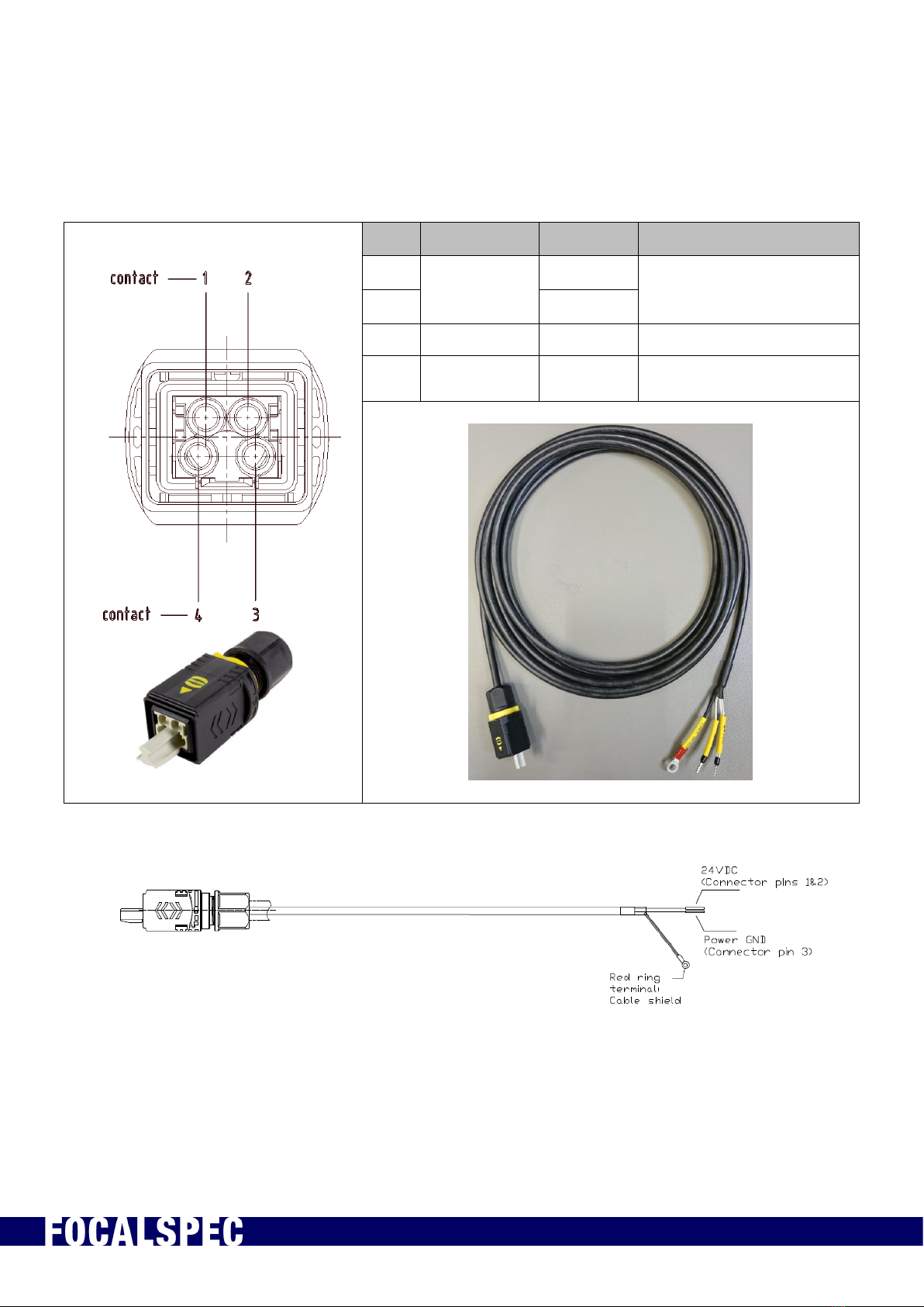
Table 3. Power cable pinout
Pin
Color
Name
Description
1
24VDC
24 V (21 V –28 V) / 2.3 A
2
24VDC
3
GND
Power Ground
4
Red ring
Terminal
Cable
Shield
Cable shield (connect to
system GND)
Figure 8. Power cable
NOTE 1: Connect the power cable ring terminal to system GND
2019-09-30 FOCALSPEC User quide LCI1220-1620 v1.0 16/31
FocalSpec Oy • Elektroniikkatie 13, FI-90590 Oulu • www.focalspec.com
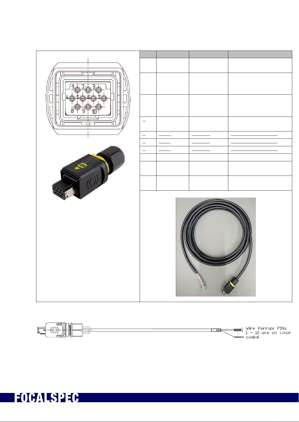
Table 4. Signal cable pinout (pins 5 to 7 not in use till later SW update)
I/O 1 PINOUT
Pin
Color
Name
Description
1
White
Input GND
Common ground for
inputs
2
Brown
Input 1
Input 1 (5V & 24 V,
default encoder A
input)
3
Green
Input 2
Input 2 (5V & 24 V,
default encoder
disable-input)
4
Yellow
Input 3
Input 3 (5V & 24 V,
default zero input)
5
Grey
Input 4
Input 4 (5V & 24 V)
6
Pink
Input 5
Input 5 (5V & 24 V)
7
Blue
Input 6
Input 6 (5V & 24 V)
8
Red
Output 1
24 V Output 1 (250 mA)
9
Black
Output 2
24 V Output 2 (250
mA)
10
Violet
GND
Digital GND (for
Output use)
Figure 9. Signal cable
2019-09-30 FOCALSPEC User quide LCI1220-1620 v1.0 17/31
FocalSpec Oy • Elektroniikkatie 13, FI-90590 Oulu • www.focalspec.com
Table 5. Input / Output parameter values.
Input / Output Parameter
Value
Sensor Power supply voltage (recommended)
24VDC
Power supply unit requirements (PSU):
24VDC@4A
Input signal voltage (operating range)
3.5V - 26V
Input signal Maximum pulse rate
150 kHz
Input signal current Min
2.7 mA
Input signal current Max
15 mA
Output signal current Max (2 output pins)
250 mA
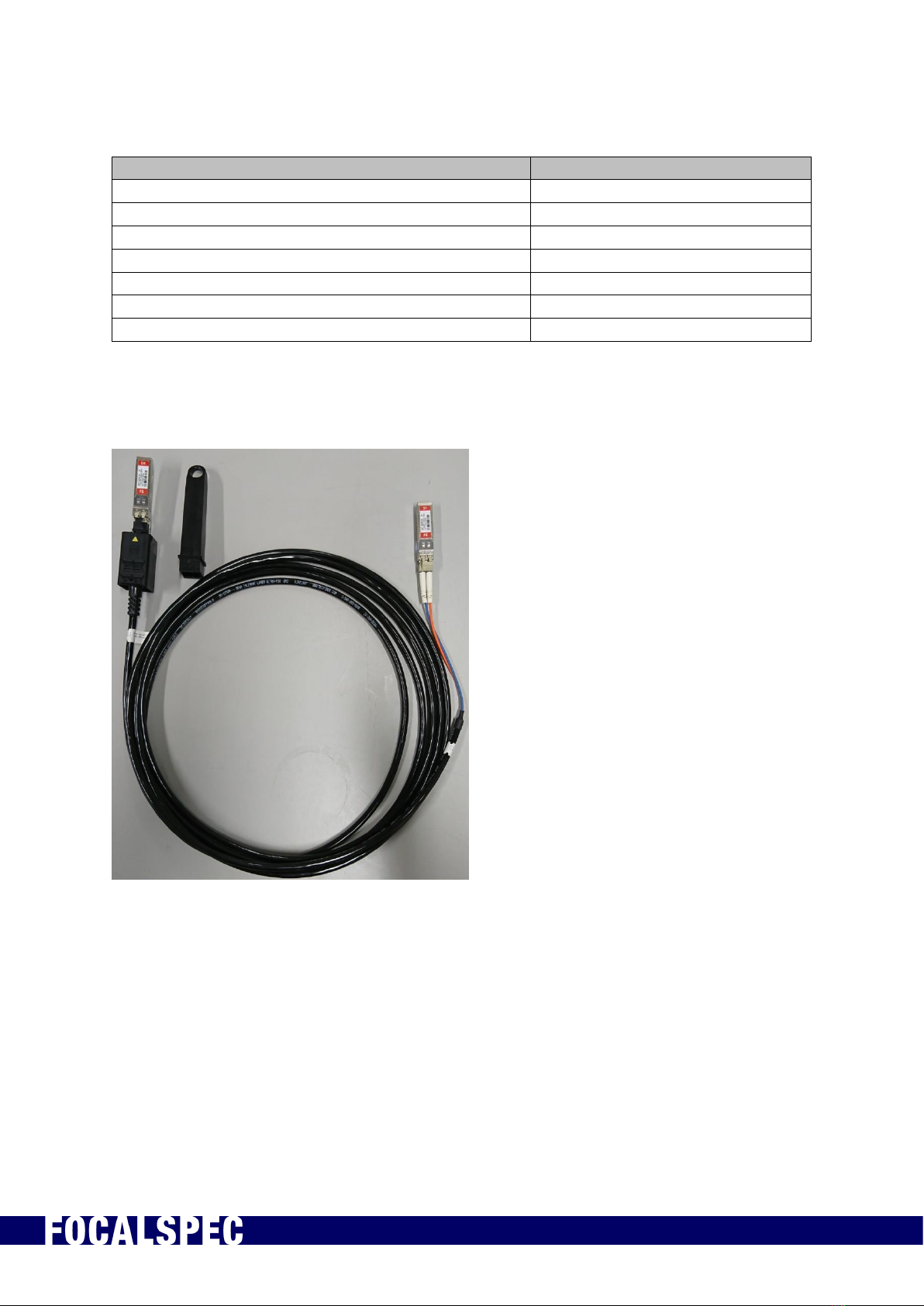
Figure 10. Optical cable with SFP+ modules in both ends
2019-09-30 FOCALSPEC User quide LCI1220-1620 v1.0 18/31
FocalSpec Oy • Elektroniikkatie 13, FI-90590 Oulu • www.focalspec.com
Figure 11. Optical cable SFP+ module
2019-09-30 FOCALSPEC User quide LCI1220-1620 v1.0 19/31
FocalSpec Oy • Elektroniikkatie 13, FI-90590 Oulu • www.focalspec.com
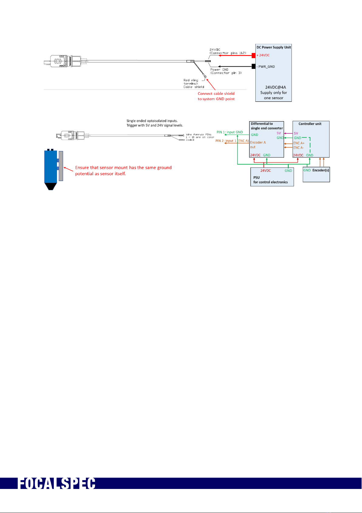
Figure 12. Example wiring for sensor connection
NOTE 1: Connect the power cable ring terminal to system GND
NOTE 2: Ensure that the sensor mount has the same ground potential as the sensor
itself.
This manual suits for next models
1
Table of contents
Popular Accessories manuals by other brands


Conspec Controls
Conspec Controls CS0352-MP user manual

Kathrein
Kathrein ESD 44 quick start guide

Maclean Energy
Maclean Energy MCE359 manual

Campbell
Campbell 253 product manual

Hubbell
Hubbell BTSMP-HMO Installation and operation instructions

Lucky Reptile
Lucky Reptile Herp Nursery II operating instructions