OLEI LR-1BS3 User manual

Sensing Reality!
LiDAR Sensors
LR-1BS3/5 Series
User Manual
This manual is only applicable to LR-1BS3/3D/5/5D
Please read this user manual for best product performance before using the product.
Be sure to keep this manual properly for future reference.
OMEN-1BS35-202202

User Manual LR-1BS35
OMEN-1BS35-202202
目录
1. About this documen ...........................................................................................................1
2. Safety information..............................................................................................................1
3. Product introduction...........................................................................................................1
4. Installation and operation ...................................................................................................1
4.1. Mechanical interface.................................................................................................1
4.2. Pin and wire color assignments ................................................................................ 2
4.3. Communication interface..........................................................................................4
5. Measurement principle.......................................................................................................5
6. Data packet format .............................................................................................................5
6.1. Overview...................................................................................................................6
6.2. Definition of Header ................................................................................................. 6
6.3. Definition of data block ............................................................................................ 6
6.4. Data conversion ........................................................................................................7
7. Parameter configuration .....................................................................................................8
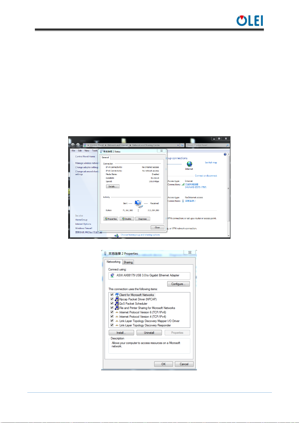
7.1. Parameter configuration of web page ....................................................................... 8
7.2. Configuration of OlamViewer ................................................................................10
8. Troubleshooting................................................................................................................10
Appendix A Data packet ........................................................................................................ 11
Appendix B Mechanical Dimensions .................................................................................... 11
Appendix C Example of Electrical Connection.....................................................................12
Appendix D Firmware Upgrade............................................................................................. 12
Appendix E Suggestions on Mechanical Installation ............................................................13
Appendix F Cleaning of sensor..............................................................................................16
F.1 Notice ......................................................................................................................16
F.2 Materials required ...................................................................................................16
F.3 Cleaning method ...................................................................................................... 16

User Manual LR-1BS35
OMEN-1BS35-202202 1
1. About this documen
This document summarizes supplementary information on mounting and electrical
installation as well as measured value output format of the LR-1BS3/5. It is aimed at sufficiently
qualified personnel for the purposes of installation, commissioning and further data processing.
Notes on commissioning, configuration and maintenance can be found in the LR-1BS3/5
operating instructions.
2. Safety information
Read the notes on mounting and electrical installation before carrying out these tasks;
Read additionally the LR-1BS3/5 operating instructions to familiarize yourself with the
device and its functions;
The LR-1BS3/5 complies with laser class 1;
Only use the device in permissible ambient conditions (e.g. temperature, ground potential).
Any applicable legal regulations or regulations of other authorities will have to be observed
during operation;
Opening the screws of the LiDAR housing will invalidate any warranty claims against
OLEI;
Repairs may only be performed on the LiDAR by trained and authorized OLEI service
personnel.
3. Product introduction
The LR-1BS3/5 is an opto-electronic laser scanner that electro-sensitively scans the
perimeter of its surroundings at a single plane with the aid of laser beams. The LR-1BS3/5
measures its surroundings using two-dimensional polar coordinates based on its measurement
origin.
With a scanning angle range of 270°, LR-1BS3/5 detects and outputs the target's angle,
distance and signal strength to facilitate the SLAM system to better identify the target.
Thus LR-1BS3/5 has been widely applied to industries such as robot obstacle avoidance,
safety monitoring, industrial automation, and intelligent logistics.
4. Installation and operation
4.1. Mechanical interface
The LiDAR can be installed in two ways: back-mounted and bottom-mounted.
Back-mounted
There are two M3 screw holes (hole depth is 3mm) at the back of the LiDAR.

User Manual LR-1BS35
OMEN-1BS35-202202 2
Figure 1: Back mounting interface of LR-1BS3/5
Bottom-mounted
There are two M3 screw holes (hole depth is 3mm) at the bottom of the LiDAR.
Figure 2: Bottom mounting interface of LR-1BS3/5
4.2. Pin and wire color assignments
LR-1BS3/5 is equipped with a "Power/IO" connection and an "Ethernet" connection.

User Manual LR-1BS35
OMEN-1BS35-202202 3
Figure 3 Diagram of electrical interface
4.2.1 "Power/IO" connection
NO.
definition
Cable color
1
GND
black
2
VCC
red
3
GND_IO
gray
4
VCC_IO
brown
5
OUT0
blue
Table 1 Definition of "Power/IO" connection
Figure 4 Diagram of "Power/IO" connection
4.2.2 Ethernet connection
NO.
definition
1
TxData+:Send +
2
TxData-:Send -
3
RxData+:receive +
4
RxData-:receive -
Table 2 Definition of Ethernet connection
Figure 5 Diagram of Ethernet connection
Ethernet
Power & IOcable
Power & IO
Ethernet

User Manual LR-1BS35
OMEN-1BS35-202202 4
4.3. Communication interface
The LR-1BS3/5 is connected to the computer by a RJ-45 Ethernet interface. The computer
IP address should be set up before communication. The LiDAR and computer IP must be set up
in the same subnet without any conflict. The host port is 2368 by default.
The factory default settings are as follows.
Computer IP:192.168.1.10
Computer subnet mask:255.255.255.0
The default factory settings of LiDAR are as follows
LiDAR IP:192.168.1.100
LiDAR subnet mask:255.255.255.0
The operation steps are as follows
Figure 6 Step 1 of computer IP setting
Figure 7 Step 2 of computer IP setting

User Manual LR-1BS35
OMEN-1BS35-202202 5
Figure 8 Step 3 of computer IP setting
5. Measurement principle
Figure 9 Diagram of LR-1BS3/5 LiDAR work principle
As is shown in the figure above, LR-1BS3/5 measures distance by using the time-of-flight
principle. The LiDAR emits pulsed laser beams using a laser diode. If one of these laser pulses
hits an object or a person, this is reflected at its surface. The reflection is detected in the LiDAR's
receiver by a photodiode. The LiDAR calculates the distance to the object from the transit time
required by the light from emission of the beam to receipt of the reflection. The calculation
method is as follows:
𝐷 = 𝐶𝑇
2
D-Detection distance
T-flight time
C-speed of light
6. Data packet format
LR-1BS3/5 can realize laser point cloud data transmission. Please refer to the following
for the analysis of LiDAR point cloud data.
The information transmission between LR-1BS3/5 and the computer follows UDP
Laser transmitter
Detector

User Manual LR-1BS35
OMEN-1BS35-202202 6
standard network protocol. The data adopts the Little-endian format,the low byte is in the front,
and the high byte is in the back.
6.1. Overview
Total length of data packet is 1240 bytes, among which header accounts for 40 bytes, data
returned by laser is 1200 bytes.
Figure 10 Format of point cloud information packet
The total length of the data frame is 1240 bytes, among which:
Frame header: 40 bytes.
Data block: 150×8=1200 bytes.
6.2. Definition of Header
Total length of data packet is 1240 bytes, among which header accounts for 40 bytes, data
returned by laser is 1200 bytes.
Offset
length
Description
0
4
Identifier, fixed as 0xFEF0010F
4
2
Protocol version, currently 0x0200
6
1
Distance ratio, actual distance value = distance reading ×distance ratio
(mm)
7
3
Brand code, expressed in capitalized letters and numbers, fill in with
‘\0’ in the end if isn’t long enough.
10
12
Sales model string ending with ’\0’
22
2
Internal model code
24
2
hardware version
26
2
Software version
28
4
Timestamp, unit: ms,
32
2
Bit[14:0]: Rotation rate
BIT 15:rotation direction(0:clockwise,1:anticlockwise)
34
1
Safe zone status, same as the hardware INPUT/OUTPUT
BIT[3:0]: Same as OUTPUT[3:0]
BIT[7:4]: Same as INPUT[3:0]
35
1
Error status, the corresponding position 1 indicates an error
BIT0: Motor fault,
BIT1: Power fault,
BIT2: Temperature fault
36
4
Reserved (detailed meaning to be determined)
Table 3 Definition of header file
6.3. Definition of data block
Total length of data packet is 1240 bytes, among which header accounts for 40 bytes, data
returned by laser is 1200 bytes.

User Manual LR-1BS35
OMEN-1BS35-202202 7
Table 4 Definition of data block
6.4. Data conversion
6.4.1 Angle calculation
Details on calculating angle of LR-1BS3/5 is shown as below:
1)obtain angle value:0xaa & 0x1d
2)interchange of high bits and low bits:0x1d & 0xaa
3)combine into an unsigned hexadecimal number:0x1daa
4)convert to decimal:7594
5)multiply by minimum resolution:0.01°
6)result:75.94°
6.4.2 Distance calculation
Details on calculating distance of LR-1BS3/5 is shown as below:
1)obtain distance value:0x11 & 0x12
2)interchange of high bits and low bits:0x12 & 0x11
3)combine into an unsigned hexadecimal number:0x1211
4)convert to decimal:4625
5)multiply by distance ration:suppose distance ration is 1mm
6)result:4625mm
6.4.3 Calculation of signal strength
The signal strength calculation method of LR-1BS3/5 is shown in the following example:
1) Obtain the signal strength value: 0x11 & 0x12
2) interchange of high bits and low bits: 0x12 & 0x11
3) Combine into an unsigned hexadecimal number: 0x1211
4) Converted to decimal number: 4625
5) Results: 4625
Offset
length
Description
0
2
Angle,unsigned integer,valid range:0~35999
Unit :0.01°/LSB,indicating range:0°~359.99°
Note:If this value is greater than or equal to 0xFF00, it means that this data
block is invalid and must be ignored .
2
2
Distance reading, unsigned integer.
The measurement distance is determined by the distance ratio of the header,
that is, measured distance="the reading value × the distance ratio of the
header" (unit: mm).
4
2
Signal strength indicates the strength of the received signal, ranging from 0
to 65535.
6
2
Reserved (detailed meaning to be determined)

User Manual LR-1BS35
OMEN-1BS35-202202 8
7. Parameter configuration
7.1. Parameter configuration of web page
Web page parameter configuration method of LR-1BS3/5 is as follows:
Open the browser (please use Chrome,Firefox, Edge or other standard browsers), and
enter the LiDAR IP address;
"Model" and "Version" at the top of the UI indicate the product model and firmware
version;
"Temperature", "Voltage" and "SafeArea" on the right side of the UI are the LiDAR
parameters displayed in real time, indicating the temperature, voltage and current active
Bank. When the font color of parameter turns red, please check whether the LiDAR is
malfunctioning;
Automatically read the current settings of LiDAR by refreshing the page;
Select the desired speed through "Motor RPM": 600/900/1200/1500
(The corresponding scanning frequency is 10/15/20/25HZ ), and click "SetConfigs" to
confirm;
Set the LED indicator ON and OFF through "Led Marquee", and click "Set Configs" to
confirm;
Set the ON and OFF of the LiDAR safety function through "Safe Area", and click "Set
Configs" to confirm;
Select input mode of "safe bank" trough "Safe bank input" (GPIO mode is not available for
1BS3/5);
Set the mode of the LED indicator through "Led Mode";
Select current Bank through "Safe bank config" when "Safe bank input" is “Software”;
Set receiving computer IP and port through "Host IP & Port".Up to 3 groups can be set.
Click to add a group, click to delete a group.
Enable/disable the DHCP function: the LiDAR dynamically obtains an IP address from the
DHCP server (ON), and the LiDAR needs to set up a static IP address (OFF);
Modification of LiDAR IP: Enter the new IP into the LiDAR IP column (must be in the
same network segment as the local IP), click the "Set Network" to confirm, and the
modification is complete after the LiDAR is powered on again

User Manual LR-1BS35
OMEN-1BS35-202202 9
Figure 11 Parameter configuration of web page
Figure 12 Advanced configuration page

User Manual LR-1BS35
OMEN-1BS35-202202 10
7.2. Configuration of OlamViewer
The OlamViewer interface is shown as following. Please refer to OlamViewer software
manual for detail.
Figure 13 Sample of The OlamViewer interface
The Web page setting interface and The OlamViewer interface may change due to
continuous update of products and is subject to actual content.
8. Troubleshooting
Table 5 Troubleshooting
Problem
Method
LiDAR fails to
scan
Verify whether the power supply is properly connected
Verify whether the power voltage meets 12~32VDC
Please contact OLEI if the above conditions are normal.
LiDAR scan
produces no data
Verify whether the network connection is normal
Verify whether the IP settings on the data receiver are correct.
Try to use third-party data scraping software to verify whether data could
be obtained normally
Verify whether only one LiDAR software is enabled.
Verify whether firewall of the data receiver is disabled or if there are
other security software or processes blocking data transmission.
Please contact OLEI if the above conditions are normal.
LiDAR can not
respond when
obstacle is detected
Check if the software configuration is correct and if the
configuration file is successfully downloaded.
Verify whether the wiring at the I/O port is correct.
When the I/O port is not not connected , Bank 0 is the effective field
group by default.
The I/O port is only connected to VCC and GND. When other PIN are
not connected, Bank 15 is considered to be the valid field group by
default.
Please contact OLEI if the above conditions are all normal.

User Manual LR-1BS35
OMEN-1BS35-202202 11
Appendix A Data packet
Appendix B Mechanical Dimensions

User Manual LR-1BS35
OMEN-1BS35-202202 12
Appendix C Example of Electrical Connection
OUTPUT
Appendix D Firmware Upgrade
This appendix will explain how to use LidarUpgrade2D to upgrade the firmware version
of the LR-1BS series LiDAR.
Figure 14 Icon
D.1 Software features
For 2D LiDAR LR-1BS series firmware upgrade
D.2 Surroundings for software
- Windows 7,8,10
- .Net framework 4.5.2
D.3 Software operation
-1. Connect the LiDAR correctly. Check whether the LiDAR communication is normal.
-2. Click the File Information box or drag the firmware file in. The relevant information of the
corresponding firmware is prompted after the firmware file is correctly loaded .

User Manual LR-1BS35
OMEN-1BS35-202202 13
Figure 15 Interface of software upgrade
-3. Clicking the"Upgrade",restart the LiDAR power, the file will be downloaded to the LiDAR
automatically.
-4. Check the"Continuous mode", after the upgrade, it will automatically wait for the next
upgrade, which can be used to upgrade LiDAR firmware in batches.
Appendix E Suggestions on Mechanical Installation
When installing LiDAR, pay attention to the following points:
1. Please remove the transparent protective film on the window when using it on site.
2. Make it as immune to shock and vibration as possible..
3. So that it is not exposed to any direct sunlight (window, skylight) or any other heat sources.
to prevent the internal temperature of the device from rising.
4. It is recommended that the mounting base used to fix the LiDAR be as flat as possible.
5. The positioning column on the mounting base should strictly follow the depth of the
positioning column at the bottom of the LiDAR, and should not be higher than 4mm. It is
recommended to use aluminum alloy mounting base for better heatdissipation .
6. When installing the LiDAR, if the LiDAR has contact mounting surfaces on both top and
bottom, please make sure that the distance between the mounting surfaces is greater than the
height of the LiDAR to avoid squeezing.
7. The tilt angle should not exceed 90 degrees when the LiDAR is installed.Excessive tilt angle
will affect the life of the LiDAR.
8. When arrange the wiring of the LiDAR, wiring on the LiDAR should not be too tight; keep
the wiring loose.
In order to avoid any influence to the measurement accuracy due to mutual interference
between LiDARs, we recommend the following installation. (Α≥6°, H≥200mm, the position of
the line segment in the diagram represents the LiDAR emission position)

User Manual LR-1BS35
OMEN-1BS35-202202 14
Figure 16 Placement of two LiDARs opposed to each other
Figure 17 Crosswise placement of two LiDARs
Figure 18 Placement of two LiDARs with parallel offset
Figure 19 Placement of two LiDARs with parallel offset, one of these upside down

User Manual LR-1BS35
OMEN-1BS35-202202 15
Figure 20 Placement of two LiDARs upside down, parallel offset
Figure 21 Placement of two LiDARs with parallel offset, one of these upside down
The emission position of the 2D LiDAR from the reference plane is as follows:
Figure 22 Light emission position of LR-1BS, LR-1B, LR-1F

User Manual LR-1BS35
OMEN-1BS35-202202 16
Appendix F Cleaning of sensor
OLE-LiDAR, especially the ring-shaped protective cover, should be kept clean in order to
accurately sense the surrounding environment.
F.1 Notice
Please read Appendix E thoroughly and carefully before cleaning OLE-LiDAR, otherwise
improper operation may damage the equipment.
F.2 Materials required
1. Clean fiber cloth
2. Neutral soap spray
3. Clean water spray
4. Isopropanol solvent
5. Clean gloves
F.3 Cleaning method
If there are only some dust on the surface of the LiDAR, directly use a clean fiber cloth
with a small amount of isopropyl alcohol solution to gently wipe the surface of the LiDAR, and
then wipe it with a dry and clean fiber cloth.
If there are mud or other blocky foreign matter on the surface of LiDAR, first spray clean
water on the surface of the dirty part on the LiDAR to remove the mud and other foreign matter
(Note: please do not wipe off the mud directly with a fiber cloth, as this may scratch the surface,
especially the surface of the protective cover). Then spray with soapy water on the dirty parts,
since the lubricating effect of soapy water could accelerate the separation of foreign materials.
Gently wipe the surface of the LiDAR with a fiber cloth, be careful not to scratch the surface.
Finally, clean the soap residue on the LiDAR surface with clean water (if there are still residues
stains on the surface, use an isopropyl alcohol solution to clean it again), and wipe it with a dry
microfiber cloth.

User Manual LR-1BS35
Official WeChat
Regarding changes in specifications, etc., without notice!
Hangzhou Ole-systems Co., Ltd.
No. 35, Jiuhuan Road, Jianggan District,
Hangzhou City, Zhejiang Province, China
Web: www.ole-systems.com
Email: [email protected]
TEL: (+86) 400 102 5850
© Copyright: Hangzhou Ole-systems Co., Ltd.
Release: 2022-02
This manual suits for next models
3
Table of contents
Other OLEI Accessories manuals
Popular Accessories manuals by other brands

Becker
Becker Centronic SunWindSet SWS441-II technical information

Carrier
Carrier Omnizone 50XCR06-24 Installation, Start-Up and Service Instructions

Powelectrics
Powelectrics Metron 4 manual

PHOENIX MANUFACTURING
PHOENIX MANUFACTURING Aerocool Pro Series owner's guide

Di-soric
Di-soric OGL 051 P3K-TSSL Connection diagram

daviteq
daviteq WSSFC-AC manual