FIC K8M-800T/M User manual
K8M-800T/M
MAINBOARD
MANUAL
DOCNo.: M03601
Rev. : A0
Date:9,2003
PartNo.:25-11110-00
Handling Precautions
Warning:
1.Staticelectricitymaycausedamage tothe integrated circuitson
the motherboard.Beforehandling anymotherboardoutside ofits
protectivepackaging,ensurethatyourbodycarriesno static
electric|charge.
2.Thereisadangerofexplosion ifthe batteryisincorrectly
replaced.Replaceonlywiththe sametype ofbattery,oran
equivalenttype|recommended bythe manufacturer.
3.Discardused batteriesaccording tothe manufacturer’s
instructions.
4.Neverrun the processorwithoutthe heatsinkproperlyand firmly
attached.PERMANENTDAMAGEWILL RESULT!
Observethefollowingbasicprecautionswhenhandlingthemotherboard
orothercomputercomponents:
nWearastaticwriststrapwhichis|connectedtoanaturalearth
ground.
nTouchagroundedoranti-staticsurface orametalfixturesuchasa
waterpipe.
nAvoidcontacting thecomponentson add-on cards,motherboards,
and moduleswiththegoldenfingerconnectorspluggedintothe
expansion slot.Itisbesttohandlesystemcomponentsby their
mounting brackets.
Theabovemethodspreventstaticbuild-up andcausesittobedischarged
properly.
Trademark
All trademarksmentionedinthismanualareregisteredproperlyby
therespective owners.
Handling Precautions
Thismanualmaynot,inwholeorinpart,bephotocopied,reproduced,
transcribed,translated,ortransmittedinwhateverformwithoutthe
writtenconsentofthemanufacturer,exceptforcopiesretainedbythe
purchaserforpersonalarchivalpurposes.
Notice
i
TableofContents
TableofContents
Chapter1Overview
PackageChecklist.................................................................................. 1-2
TheK8M-800T/MMainboard........................................................ 1-3
MainFeatures........................................................................................ 1-4
FICUniqueInnovation forUsers(NOVUS)-
EnhancedMainboardFeaturesand SystemSupport....................... 1-5
Chapter2Installation Procedures
1).SetSystemJumpers......................................................................... 2-2
ClearCMOS.............................................................................. 2-2
LEDTypeSelect....................................................................... 2-2
2).InstallMemoryModules................................................................. 2-3
3).InstalltheCPU.................................................................................. 2-4
ConnectATXPower................................................................ 2-5
4).InstallExpansion Cards................................................................... 2-6
5).ConnectDevices............................................................................... 2-8
FloppyDisketteDriveConnector.......................................... 2-8
IDEDevice Connectors........................................................... 2-8
FanConnectors........................................................................ 2-9
PowerConnectors................................................................... 2-9
FrontPanelBlockConnector................................................. 2-10
IRand SpeakerConnector...................................................... 2-11
ChassisIntrusion Connector................................................. 2-11
SerialIRQConnector............................................................... 2-12
Wake-On-LAN Connector...................................................... 2-12
SerialATAConnectors............................................................ 2-12
SPDIFConnectors................................................................... 2-13
1394Connectors(optional).................................................... 2-13
CDAudio-InConnectors........................................................ 2-14
TypesofRearPanelI/OConnectors..................................... 2-14
RJ45LAN Connector.............................................................. 2-14
PS/2Keyboardand MouseConnector................................. 2-15
PrinterConnector..................................................................... 2-15
SerialPortConnectors(K8M-800T)...................................... 2-15
SerialPortConnectors(K8M-800M).................................... 2-16
ii
K8M-800T/MMainboardManual
Chapter3BIOSSetup
CMOSSetup Utility............................................................................... 3-1
StandardCMOSSetup .......................................................................... 3-2
AdvancedBIOSFeatures..................................................................... 3-4
AdvancedChipsetFeatures................................................................. 3-7
IntegratedPeripherals........................................................................... 3-10
PowerManagementSetup.................................................................... 3-14
PnP/PCIConfigurations........................................................................ 3-17
PCHealthStatus.................................................................................... 3-19
Frequency/VoltageControl.................................................................. 3-19
LoadOptimizedDefaults....................................................................... 3-20
Supervisor/UserPassword................................................................... 3-20
Saveand Exit Setup ............................................................................... 3-20
Exit withoutSaving................................................................................ 3-20
CRTConnector(K8M-800M)................................................. 2-16
AudioI/OJacks....................................................................... 2-17
FrontAudioConnector........................................................... 2-17
PrinterConnector..................................................................... 2-18
UniversalSerialBusConnectors........................................... 2-18

1-1
Overview
Overview
Chapter1
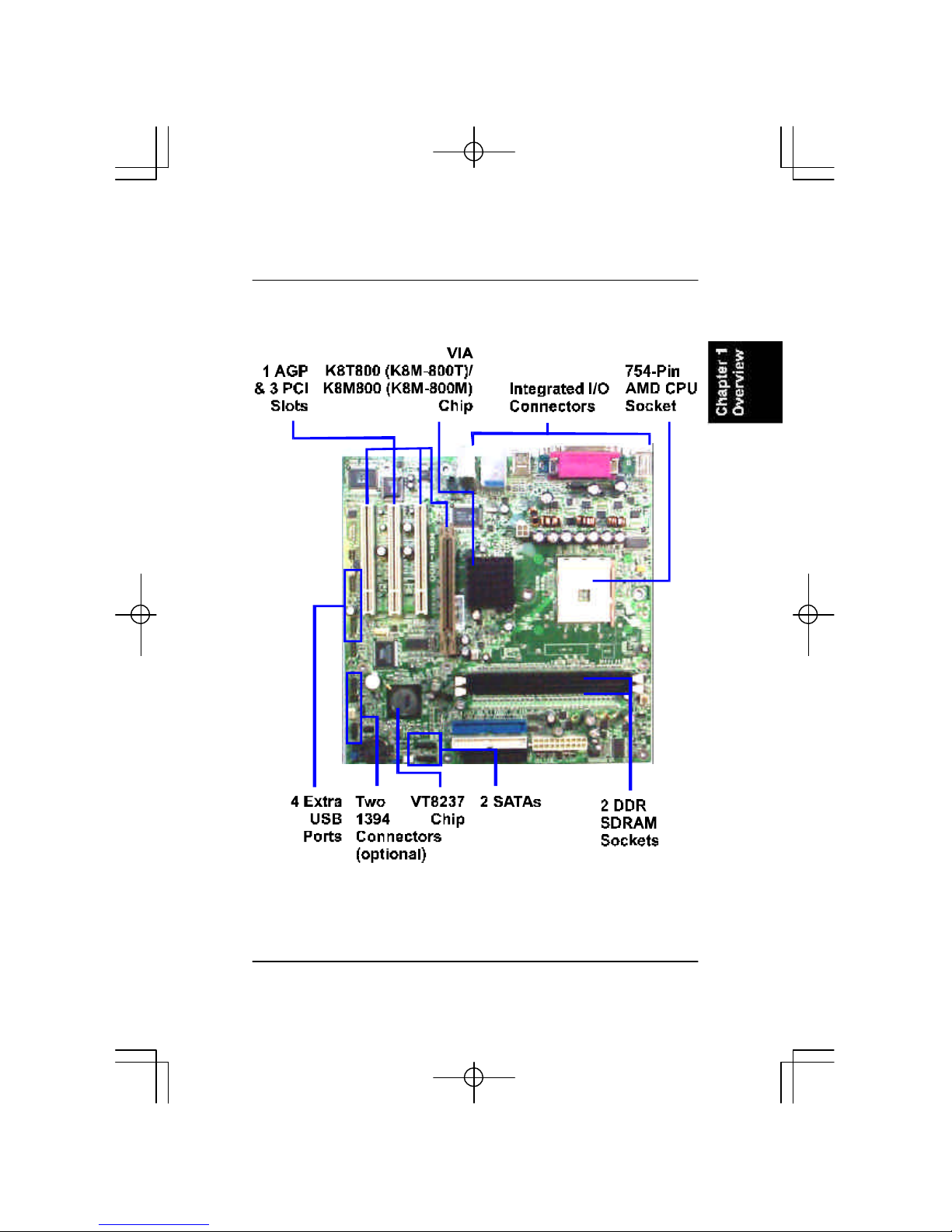
ThisnewMainboardisamicroATXsizedboardsupportingthelatestgenera-
tion ofAMD64 processorsatFSB800MHz.MemoryisuptoDDR400MHz
and has2DDRSDRAMDIMMsforup to2GBs.Thisboardprovidesusers
withanATA133datatransaction forperipheralIDEdrives.
Thisboardisbasedupon thehigh performance VIAK8T800 (K8M-800T)/
K8M800(K8M-800M)/asitsNorthBridgeand theVIAVT8237 asits
SouthBridge.ItsAGPfunctionssupportedAGP3.0interface and themost
robust3Dgameswithsoftwareenvironments.
Theboardfeaturesonboardaudioand LAN function;also,theserialATA
featurereplacesthestandardparallelATAphysicalstorageinterface and al-
lowsfutureenhancementstothecomputing platform.Itiscompletelysoft-
warecompatiblewithparallelATA,requiring no modification toyouroperat-
ing system.Formoredetails,pleasereadthehelpfileinthelstUtilitiesCD.
ThismainboardcomeswithaversatilerangeofI/Ofeaturessuchasserialport
(s)and/or1CRTport,(K8M-800T:2COMports,no CRTport; K8M-800M:1
COMport+1CRTport),1parallelport,1LAN,2optionalIEEE1394,1PS/2
mouseand keyboardconnector,8USBports,and 1mediaconnector(front
audio,Line-in,Line-outand Mic-in).Inaddition,theboardisequippedwith2
dualchannelenhancedPCIbusmasterIDEconnectors.Ampleexpansion is
availablethrough 3PCIand 1AGPallowforenjoymentoftheCPU’sbenefits
wthinternetapplicatons,video/3Dgraphicsperformance,and soforth.
OtherkeyfeaturesareRemoteOn/Off,AutoPowerFailureRecovery,inte-
gratedtemperaturemonitoring and systemfancontrol.Also,includedarealst
UtilitiesCDwithenhanceddriversand afewbundledsoft-waresolutions.

1-2
K8M-800T/MMainboardManual
PackageChecklist
If you discoverany itembelowwasdamagedorlost,pleasecontactyour
vendor.
NOTE:A1stUtilities CDthatcontainspatchfiles,onboardvideo/
audiochipdrivers,related onlinehelpandotherusefulinformation
can be found inyourmainboardpackage.
Pleaseinstallthe 1stUtilitiesimmediatelyafteryourWindowsoper-
ating systeminstallation iscomplete.Toinstall,placeyour1stUtil-
ityinthe drive.Anoperating menu will appearson yourmonitor.
PleaseselectAutoInstallation.The CD will automaticallydetect
whichsoftwaretools(patchfiles,drivers)the mainboardneeds.
Press OKbutton togo through the wholeinstallation procedurein
averystraightforwardandeasyway.TheCDalsoprovidesyou with
awaytoselectwhichpatchfilesand softwaredriversthe onboard
chipsuse.Themainmenu of1stUtilities listsall thefunctions
thatareallowedbythisboard.
1-3
Overview
TheK8M-800T/MMainboard
1-4
K8M-800T/MMainboardManual
MainFeatures
nCPU
Athlon64processorsfrom3200+and up* atFSB800MHz
(*:nottestedwhenthismanualwasprinted)
nChipset
NorthBridge:VIA®K8T800 (K8M-800T)
/K8M800(K8M-800M)
SouthBridge:VIA®8237
nMemory
2memorysockets:
support184-pinDDR266/333/400(PC2100/PC2700/PC3200*)DDR
SDRAMmemorysize up to2GBstotal
nExpansionSlots
1AGP8XSlot
3PCISlots
nAudioFeatures
RealtekALC655/658(duallayout)controller;AC97
LINE_IN,LINE_OUT,MICROPHONE_INJack
5.1audiochannel
Frontaudiopinheaders
nI/OPorts
2IDEconnectors-
PIO,BusMaster,UltraDMA66/100/133up to4devices
COM1and COM2
1parallelport
PS/2mouseand PS/2keyboard
8USBports

1-5
Overview
nMountingHoles
9holes
nMainboardSize
9.6x9.6(unit:inch)
nIEEE1394 Ports(optional)
VT6307L
2ports
1bracketwithcable
nSATAConnections
VT8237
RAID0,1,0+1
2optionalcables
nLAN
RTL8100C10/100MFastEthernet/
8110SGigabit Ethernet(duallayout)
FICUniqueInnovation forUsers(NOVUS)-
EnhancedMainboardFeatures and SystemSupport
nBIOSGuardian
BIOSGuardianeffectivelyactsasafire-wallagainstvirusesthatcanattack
theBIOSwhilethesystemisrunning and whendefaultisenabled.Please
readPage3-7formoredetailedinformation.NOTE:BIOSGuardianmust
bedisabledbefore youreflashBIOS.

1-6
K8M-800T/MMainboardManual
nEasyKey
Insteadofcompleting themulti-layeredBIOSsetup process,these3Easy
Keyfunctionsprovidedirectaccess totheSub-Menu whencompleting
BIOSsettingsadjustments.
Easy-Keysareasfollows:
Ctrl+c:Toenterclocksettingsmenu.
Ctrl+p:ToloadPerformanceDefault settingsand restart.
Ctrl+f: ToloadFail-SafeDefault settingsand restart.

2-1
Installation Procedures
Chapter2
Installation Procedures
Themainboard hasseveraluser-adjustablejumperson theboard thatallowyou to
configureyoursystemto suit yourrequirements. Thischaptercontainsinformation
on thevariousjumpersettingson yourmainboard.
To setup yourcomputer, you mustcompletethefollowingsteps:
Step1-Setsystemjumpers
Step2-Install memory modules
Step3-Install theCentralProcessing Unit(CPU)
Step4-Install expansioncards
Step5-Connectribboncables, cabinetwires, andpower supply
Step6-SetupBIOSsoftware
Step7-Install supporting software tools
WARNING:Excessivetorque maydamage the mainboard.When
using an electricscrewdriveron the mainboard,makesurethat
the torque issettothe allowablerange of5.0~8.0kg/cm.
MainboardcomponentscontainverydelicateIntegrated Circuit
(IC)chips.Topreventstaticelectricityfromharming anyofthe
sensitivecomponents,you shouldfollowthe following precau-
tionswheneverworking on the computer:
1.Unplug the computerwhen working on the inside.
2.Holdcomponentsbythe edgesand trynottotouchthe IC
||||chips,leads,orcircuitry.
3.Wearan anti-staticwriststrap whichfitsaround the wrist.
4.Placecomponentson agrounded anti-staticpad oron the bag
thatcamewiththe componentwheneverthe componentsare
separated fromthe system.
2-2
K8M-800T/MMainboardManual
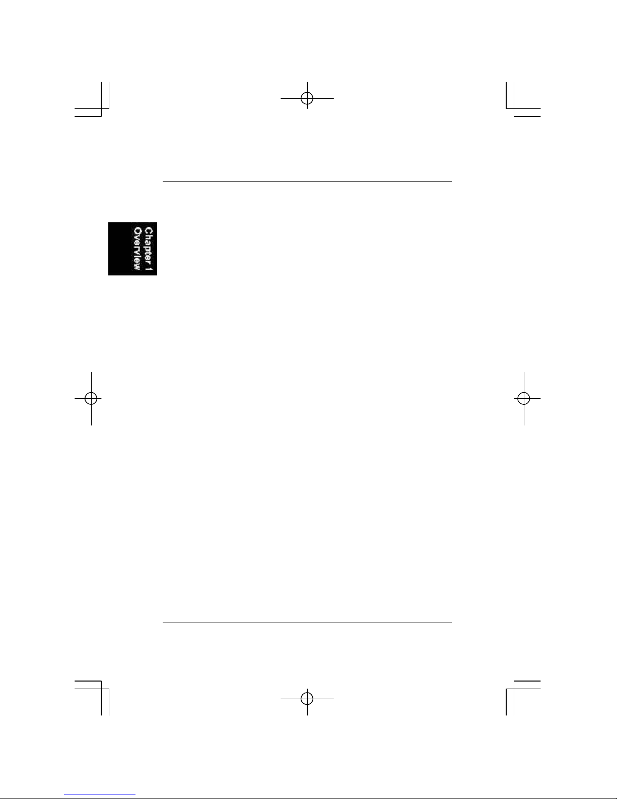
ClearCMOS
TheCMOSRAMispoweredby theonboardbutton cellbattery.
TocleartheRTCdata:
(1)Turnoff yourcomputer;
(2)Openthesystemcaseand disconnecttheATXpowercable;
(3)Place thejumpercapontothepinpair2-3foratleast6seconds
toenableCMOSclearance;
(4)Place thejumpercapontothepinpair1-2todisabletheeffectof
CMOSclearance;
(5)ConnecttheATXpowercableand closethesystemcase;
(6)Turnon yourcomputeruntilCMOSchecksumerrorappears;
(7)HolddowntheDeletekeywhenbooting;
(8)EntertheBIOSSetup tore-enteruserpreferences.
1.)SetSystemJumpers
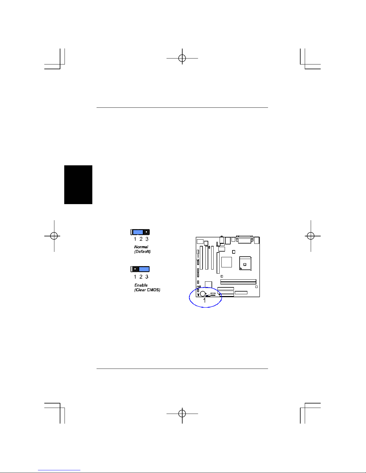
LEDTypeSelect
This2x3jumperallowyou toselectPowerLEDType,singleLEDordual
LED.
2-3
Installation Procedures
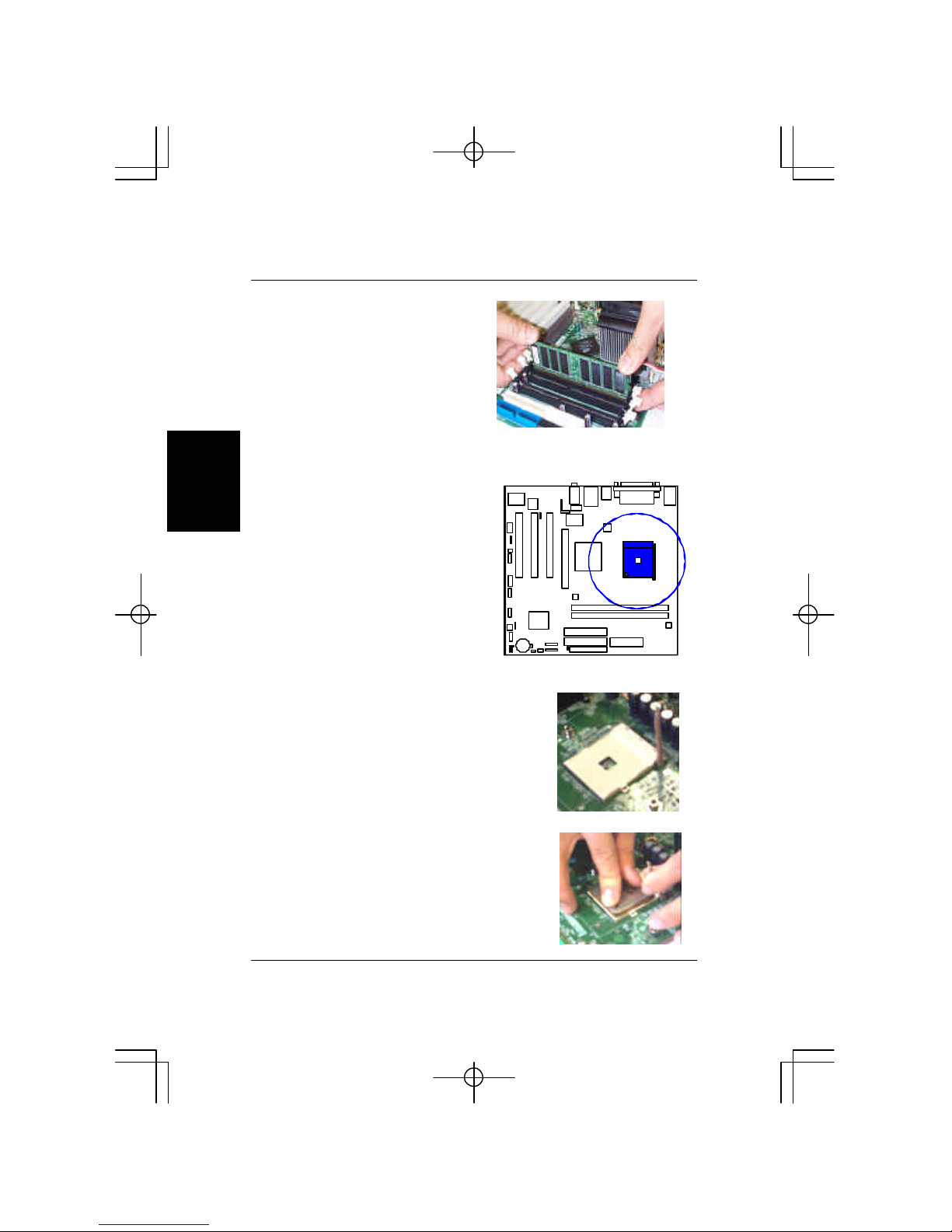
2.)Install MemoryModules
1.LocateDDRDIMM sockets
on themainboard.
2.InstallDDRDIMM straightdown
intosocket1,using bothhands,
thensocket2,and soforth.
NOTE:PleaserefertoFrontPanelBlock ConnectorSection ofthis
chapterfordetail information.
2-4
K8M-800T/MMainboardManual
3.)Install theCPU
Theprocedurebelowshowsyou
howtoinstallyourCPU,itsfan
and heatsink.Beforeyou begin,
locatetheCPUsocketon the
mainboard.
1.Swing theleverupwardto90degrees.
Press theclipsoutwardwithbothhandstoremovetheDIMM.
3.Theclipon bothendsofthe
socketwillclosetoholdtheDDR
DIMM inplace whentheDDR
DIMM reachesthebottomofthe
socket.
Themainboardhasabuilt-inSwitching
VoltageRegulatortosupportCPUVcore
autodetection.Thatis,Ithastheabilityto
detectand recognize theCPUhealthcon-
dition fromtheBIOSSetup Screen.
Applysomethermalmaterial,suchaspasteor
tape,on theCPUtop,and installafanwitha
heatsink thatisapprovedby themanufacturer
toavoidCPUdamage.Fordetailinformation,
pleaserefertotheCPUmanufacturerwebsite.
AffixtheCPUby pressing theleverdownward
and locking it besidethesocket.

2-5
Installation Procedures
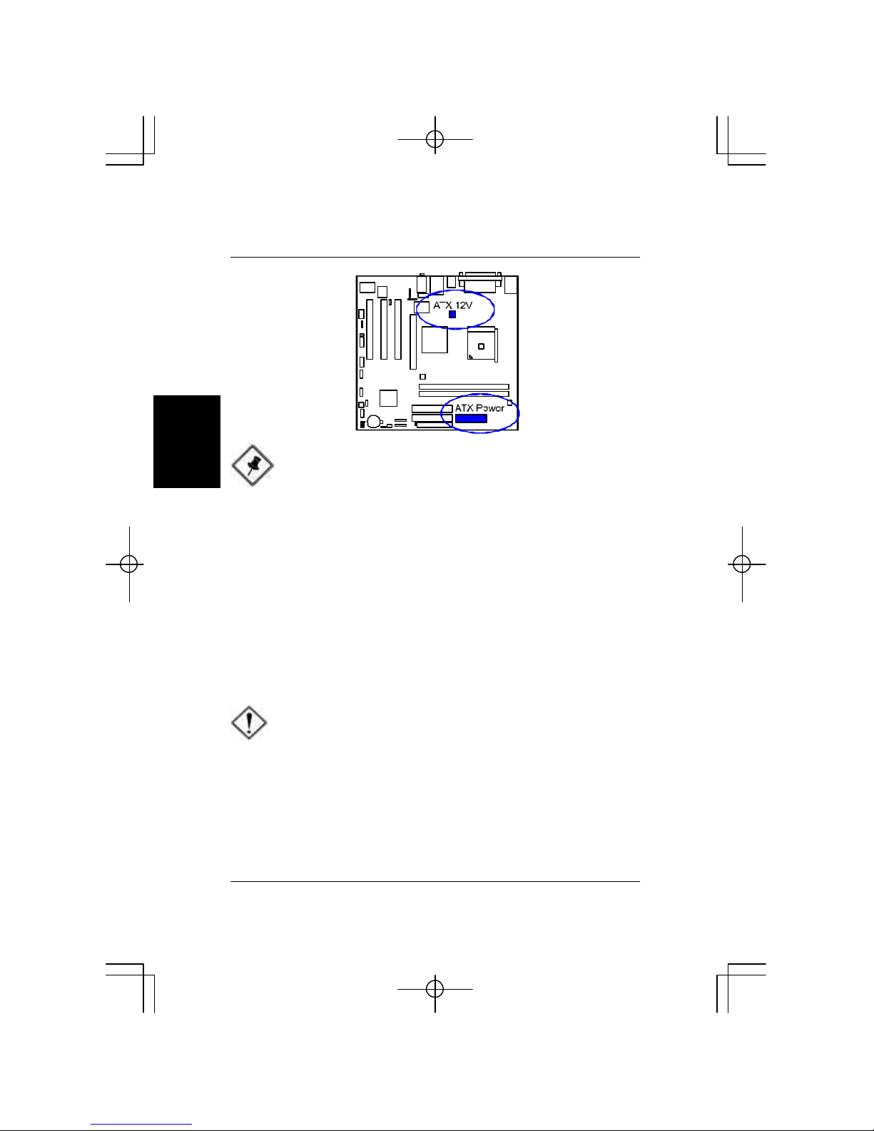
ConnectATXPower
The20-holepowerplug (top right)isconnected
totheATXpower20-pinpinheaders.The4-hole
12Vpowerplug (bottomright)isinsertedinthe
ATX_12Vpowerconnector.
Theplug fromthepowersupplycanonlybein-
sertedinoneorientation becauseofthediffer-
entholesizes.Find theproperorientation and
pushdownfirmlymaking surethatthepinsare
aligned.
3.Place thefanwithheatsinkon theCPUtop
and press downon thetwoplasticclips,
hooking themup withtheholeson thetwo
sidesoftheretention module.
4.Press thewhitebaron eachclipdownto
fastenthefanseton theretention module.
2-6
K8M-800T/MMainboardManual
CAUTION:
1.Makesuretounplug the powersupplywhen adding orremov
ing expansion cardsorothersystemcomponents.Failureto
do somaycauseseveredamage toboththe mainboardand
expansion cards.
2.Always observestaticelectricityprecautions.
3.Pleaseread Handling Precautionsatthe startofthismanual.
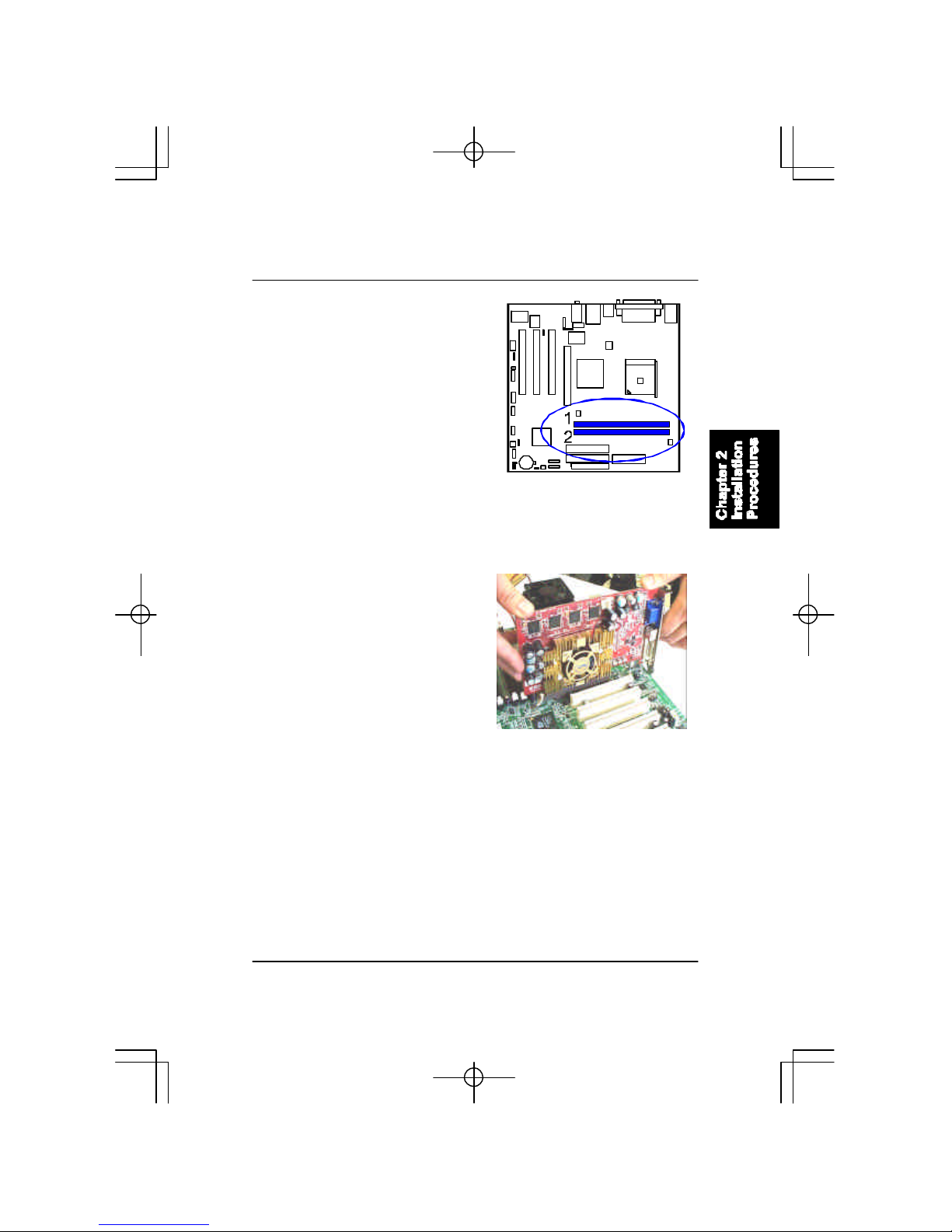
4).Install Expansion Cards
Thissection describeshowtoconnectanexpansion cardtooneofyour
systemexpansion slots.Expansion cardsareprintedcircuitboardsthat,when
connectedtothemainboard,increasethecapabilitiesofyoursystem.For
example,expansion cardscanprovidevideoand sound capabilities.The
mainboardfeaturesoneAGPand three PCIbusexpansion slots.
NOTE:
The CPUinstalling proceduresshouldbe:
1.Insertthe CPU(withitsfansinkand retention module)on the
socket.
2.Connectthe 4-pinplug ofthe powersupply
3.Connectthe 20-pinplug ofthe powersupply.
Toremovethe processor,pleasedo itinreverseorder.
2-7
Installation Procedures
1.Selectanavailableexpansion slot.
2.Removethecorresponding slotcoverfromthecomputerchassis.Un-
screwthemountingscrewthatsecurestheslotcoverandpulltheslotcover
outfromthecomputerchassis.Keeptheslotcovermounting screwnearby.
3.Pushthecardfirmlyintotheslot.
Pushdownon oneend oftheexpan-
sioncard,thentheother.Usethisrock-
ing motion untilcardisfirmlyseated
insidetheexpansion slot.Securethe
cardwiththescrewremovedinStep2.

2-8
K8M-800T/MMainboardManual
IDEDevice Connectors
Thetwoconnectors,PRIMARY
and SECONDARY,areusedfor
yourIDEharddiskdrives,CDdrives,
LS-120|drives,orIDEZIPdrives.
5).ConnectDevices
FloppyDisketteDrive Connector
Thisconnectorprovidestheconnection withyourfloppy diskdrive.
Insertthefloppy ribbon cable(below)
ontothefloppy connector.
Thecoloredstripe(indicatedby the
arrow,right)oftheribbon cablemust
beon thesamesideasPin1.
Insertthefloppy ribbon cable(below)
ontothefloppy connector.
Thecoloredstripe(indicatedby the
arrow,right)oftheribbon cablemust
beon thesamesideasPin1.

2-9
Installation Procedures
PowerConnectors
The20-pinmaleblockconnectorisconnectedtotheATXpowersupply.The
4-pinmaleblockconnectorisfortheATX_12Vpowersupply.Bothconnec-
torsarelinkedwithyourATXpowersupply.Theplugfromthepowersupply
canonlybeinsertedinoneorientationbecauseofthedifferentholesizes.Find
theproperorientation and pushdownfirmlymaking surethatthepinsare
aligned.
FanConnectors
Thetwoconnectors,CPU_FAN and SYS_FAN arelinkedtotheCPUfanand
casefan,respectively.PWR_FAN canbeusedwiththepowersupplycooling
fan.
2-10
K8M-800T/MMainboardManual
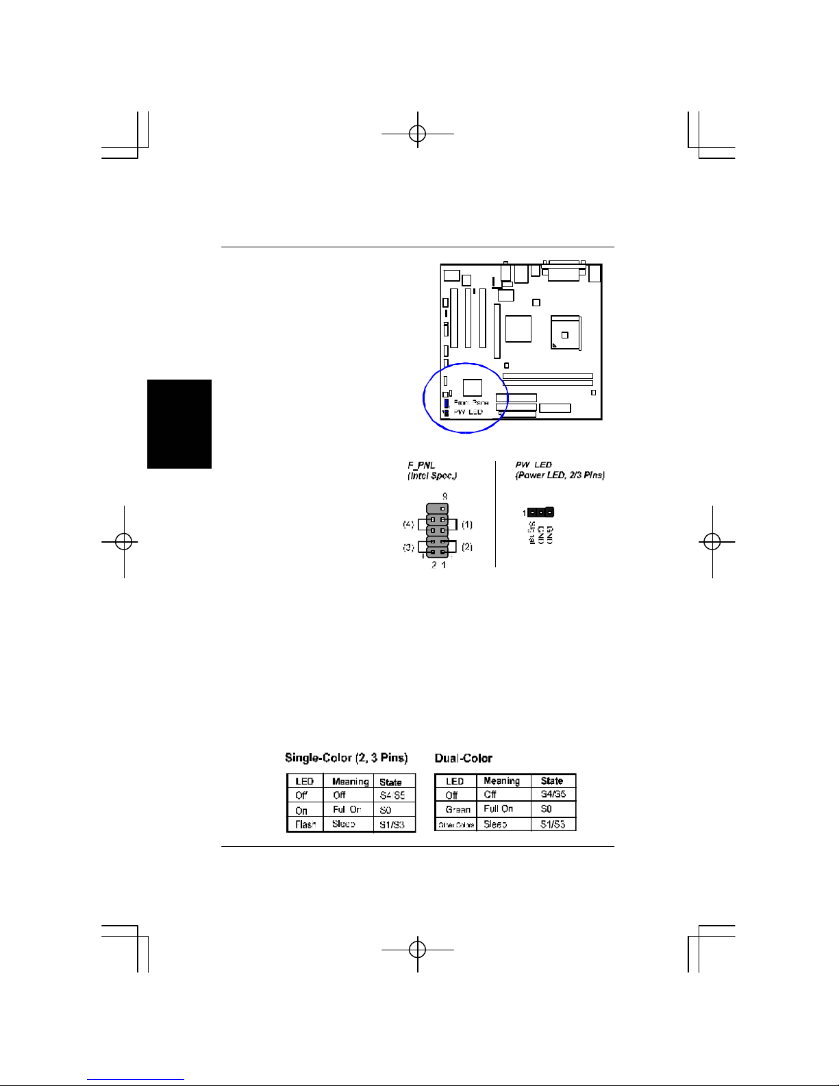
FrontPanelBlock Connector
(1)ResetSwitchisconnectedtotheresetbutton.Pushthisswitchtoreboot
thesysteminsteadofturning thepowerbutton off and on.
(2)HDD LEDisconnectedtotheIDEdeviceindicator.ThisLEDwillblink
whentheharddiskdrivesareactivated.
(3)Power (SingleandDual)/SleepLED
PleaserefertothetablesbelowfortherepresentationsofLEDstates.
Thereisalso3-PinPowerLEDconnectoron boardforthosecasesthat
havea3-pinplug.
Thisblockconnectorincludesthe
connectorsforlinking withthe
PowerLED(3-pin),HDD LED,
powerbutton,power/sleep/mes-
sagewaitingbutton,andthereset
button on thefrontpanelofthe
systemcase.Pleaseidentifythe
polaritiesoftheplug wiresforthe
casespeakerandLEDs.Pleaseask
vendoraboutthisinformation
whenyoubuythemandinstallthe
systembyyourself.Theplug wire
polaritiesofthesebuttonswillnot
affectthefunction.
Table of contents
Languages:
Other FIC Motherboard manuals


