Foerster CORCOGRAPH Ro 20 P User manual

CIRCOGRAPH®
Sensor system Ro 20 P 6.460
Operating Instructions


FOREWORD
FOREWORD
These operating instructions were written to be read, understood
and complied with in full by those persons responsible for operat-
ing the machine.
The complete operating instructions consist of the following sec-
tions:
1 Safety
2 Description
3 Installation
4 Operation
5 Maintenance
Machine faults can only be avoided and fault-free operation of the
machine can only be guaranteed through knowledge of the oper-
ating instructions.
It is therefore particularly important that all responsible persons
are familiar with and understand the full operating instructions.
Our service department or one of our representatives would be
pleased to receive suggestions about how to further improve
these operating instructions. Any questions not covered by these
instructions will also be dealt with quickly and comprehensively.
6.460 - 10/2002 I

Copyright
These operating instructions contain copyrighted information.
All rights reserved, INSTITUT DR. FOERSTER GmbH & Co. KG.
These operating instructions are intended for assembly, operating
and monitoring personnel.
Copying, reproduction or translation of these operating instructions
into other languages in whole or in part requires the express written
approval of INSTITUT DR. FOERSTER GmbH & Co. KG.
© 2002 INSTITUT DR. FOERSTER GmbH & Co. KG.
In Laisen 70, D-72766 Reutlingen
II 6.460 -08/2004

Table of Content1 SAFETY 1/1
1.1 Dangers posed by this machine 1/1
1.2 Safety information and tips 1/1
1.3 Use as intended 1/2
1.4 Dangers posed by accessories 1/2
1.5 Emissions 1/2
1.6 Danger sources 1/3
1.7 Workstations 1/3
1.8 Authorised operators 1/3
1.9 Personal safety equipment 1/3
1.10 Safety measures at the installation location 1/4
1.11 Protective safety devices 1/4
1.12 Behaviour in the event of an emergency 1/4
2 Description 2/1
2.1 Application 2/1
Testing capacity 2/1
2.2 Mode of operation 2/2
2.3 Construction 2/4
2.3.1 Test Heads 2/6
2.3.2 Rotating Head Ro 20 P 2/7
Rotor 2/7
Sensor 2/8
Rotating head electronics 2/8
Drive 2/9
Diameter adjustment 2/10
Protective nozzles standard 2/10
Precision guide 2/12
Roller guide 2/13
2.4 Technical data 2/14
2.5 Operating, storage and transport conditions 2/15
Operation 2/15
Storage and transport 2/15
Storage conditions 2/15
2.6 Dimension sheet 2/16
2.7 Standard Components 2/18
3. INSTALLATION 3/1
3.1 Setup and Connection 3/1
Electrical connections 3/2
SENSOR SYSTEM Ro 20 P
Table of Content page
6.460 - 10/2002 1
i

4. OPERATION 4/1
4.1 Dimension change 4/1
Preparation 4/1
Dimension change procedure 4/1
4.2 Selection and installation of the protective nozzles 4/2
4.2.1 Selection of the protective nozzles 4/2
Function of the protective nozzles 4/2
Standard Nozzle 4/3
Precision Nozzle 4/4
4.2.2 Required tools 4/5
4.3 Changing nominal diameter 4/6
4.3.1 Preparation 4/6
4.3.2 Removing nozzle holder 4/7
Adjustment side 4/7
Drive side 4/8
4.3.3 Changing nozzles 4/9
4.3.4 Adjusting probe clearance 4/10
4.3.5 Adjusting roller guide 4/13
4.4 Rotational speed preselection 4/13
4.5 Switching on motor 4/14
5. Maintenance 5/1
5.1 Maintenance schedule 5/1
5.2 Cleaning 5/2
5.3 Removing test heads 5/3
5.3.1 Installing test heads 5/7
5.4 List of parts subject to wear 5/8
SENSOR SYSTEM Ro 20 P
Table of Content page
26.460 - 10/2002
1SAFETY
1.1 Dangers posed by this machine
The CIRCOGRAPH sensor system Ro 20 P features protective
safety devices. It has been subjected to a safety test and safety
acceptance test. In the event of operating errors or misuse, the
machine may pose dangers and risks to
§the life and limb of the operator,
§the machine and other operator’s valuables and
§efficient operation of the machine
All persons involved in installation, commissioning, operation,
servicing and maintenance of the machine must
§be appropriately qualified and
§must strictly follow the information provided in these operating
instructions.
Your safety is at stake!
1.2 Safety information and tips
The following symbols are used in these operating instructions:
DANGER!
This warns against dangers to persons. These sections
provide you with information on what to do and what not
to do in order to prevent personal injury.
WARNING!
These sections indicate possible damage to the test sys-
tem. They provide information on what to do and what
not to do in order to prevent damage to property.
+NOTE!
These sections provide tips for the user on how to use
the system better and also provide other useful informa-
tion.
SENSOR SYSTEM Ro 20 P
SAFETY 1.1 Dangers posed by this machine
6.460 - 10/2002 1/1

1.3 Use as intended
The CIRCOGRAPH sensor system Ro 20 P is suitable only for
non-destructive testing of round material.
Diameter range 2 mm to 20 mm, continuously adjustable!
Larger diameters may not be admitted into the sensor system un-
der any circumstances.
Material with a cross-section which is anything other than round
may not be admitted into the sensor system under any circum-
stances.
The sensor system may be operated only in conjunction with a
suitable conveying mechanism and a lifting table.
On no account may you convert or modify the sensor system arbi-
trarily, for reasons relating to safety.
DANGER!
Masses rotating at high speed pose a serious danger to
your life if the machine is operated incorrectly.
Never touch the rotating sensor components.
+NOTE!
The information on operation, servicing and mainte-
nance prescribed in these operating instructions must
be followed strictly.
1.4 Dangers posed by accessories
Transport mechanisms, lifting table and external control equip-
ment must not render the protective safety devices of the
CIRCOGRAPH sensor system Ro 20 P inoperable.
1.5 Emissions
The maximum A-weighted equivalent sound pressure level lies at
82 dB(A) in a distance of 1 m from the machine’s surface and at
1.6 m above basement, measured in axial direction of the ventila-
tor. The values at the workstations of the personell are resp.
lower, also when using rotating speeds less than 18.000 rpm.
SENSOR SYSTEM Ro 20 P
1.3 Use as intended SAFETY
1/2 6.460 - 10/2002

1.6 Danger sources
The CIRCOGRAPH sensor system Ro 20 Poperates with a
rotating test system and an attached roller guide system
during operation. A person coming into contact with the roller
guide or the rotating test system may suffer very serious injuries.
Switch offthe drives before you put your hands into or touch the
sensor system. Wait for all motions to cease.
Before carrying out servicing and cleaning work, switch off the
drive for the sensor system and conveying mechanisms and dis-
connect the power supply (secure the master switch in position
OFF).
Never remove protective safety devices or render them inopera-
ble by making modifications to the system.
1.7 Workstations
The workstation is located on the electronic equipment cabinet or
on the operating panel of the CIRCOGRAPH sensor system Ro
20 P.
Do not carry out any work or tamper in any other way with the
sensor system when it is rotating.
1.8 Authorized operators
Only authorized personnel may work on the CIRCOGRAPH sen-
sor system Ro 20 P. Please comply with the minimum legal age!
The operator is responsible for the safety of third parties in the
work area.
The scopes of authority for the various activities on the sensor
system must be clearly defined and complied with.
Untrained personnel pose asafety risk!
The operator must make
- the operating instructions available to the machine operator and
- sure that the machine operator has read and understood them
1.9 Personal safety equipment
No personal safety equipment is required.
SENSOR SYSTEM Ro 20 P
SAFETY 1.6 Danger sources
6.460 -08/2004 1/3

1.10 Safety measures at the installation location
The CIRCOGRAPH sensor system Ro 20 P must be installed
stably on a machine foundation provided for it and must be firmly
anchored to the foundation. If this is not done, this will pose a po-
tentially lethal risk.
+NOTE!
Ensure that the area surrounding the workstation is al-
ways clean and unobstructed by issuing appropriate
in-company instructions and conducting inspections.
1.11 Protective safety devices
The CIRCOGRAPH sensor system is shut down
§when opening the housing (safety switch on the rotor cover)
§with the switch on the operating panel or on the electronic
equipment cabinet
§with the EMERGENCY-STOP switch on the operating panel
(EMERGENCY-STOP has to be linked with motor control)
The protective safety devices
§are installed to ensure the safety of the operating staff
§may not be modified, removed or bypassed by making modifi-
cations to the sensor system under any circumstances.
1.12 Behavior in the event of an emergency
In an emergency, please immediately press the red
EMERGENCY-STOP switch. Have authorized personnel remedy
the cause of the fault immediately.
SENSOR SYSTEM Ro 20 P
1.10 Safety measures at the installation location SAFETY
1/4 6.460 - 10/2002

DECLARATION of CONFORMITY
Manufacturer: INSTITUT DR. FOERSTER GmbH & Co. KG Phone. +49 7121 140-0
In Laisen 70 Fax +49 7121 140-488
GERMANY www.foerstergroup.de
Responsibility for
documentation: Dr. Juergen Schroeder
Product: CIRCOGRAPH DS Ro20
Type: 6.460.01-1001
Serial No.: 00309 and higher
We declare, that this product complies with the requirements of following European Directives
and corresponding Standards:
European Directive 2006/42/EC: Safety of machinery
European Standards EN 12100-1, -2, EN 14121-1, EN 60204-1
European Directive 2006/95/EC: Safety of electrical apparatus
European Standard EN 61010-1
European Directive 2004/108/EC: Electromagnetic Compatibility
European Standard EN 61326-1
This declaration relates exclusively to the machinery in the state in which it was placed on the market, and excludes
components which are added and/or operations carried out subsequently by the final user.
Reutlingen, December 29, 2009
Dr. Juergen Schroeder
General Manager - Division Test Systems

Notes:
SENSOR SYSTEM Ro 20 P
1/6 6.460 - 10/2002

BESCHREIBUNG
2Description
2.1 Application
Nondestructive testing of ferromagnetic, austenitic and
nonferromagnetic round materials (wires, bars and tubes) for sur-
face flaws in conjunction with the CIRCOGRAPH®DS 6.430 (two
channel with Clearance Compensation) or CIRCOGRAPH®CP6.412
(one-channel without Clearance Compensation) testing and eval-
uation electronic equipment and a suitable mechanical handling
system
§Diameter range of testing material 2 to 20 mm
§Preferably continuous testing, also separate piece testing
§Surface free of scale, wherever possible bright
§Testing mode without physical contact at rotational speeds
upto 18.000 rpm
§End condition free of projecting burrs
§Max. test material temperature +80 °C
§Testheads with tracking width 1,5 / 2,5 und 5 mm [BS]
Typ N as standard,
Typ DF for encreased clearance (prefered for FE material)
§Quickcange nozzeles inside and outside
§Blower facilitiy for cooling and maintaining cleanliness
§Precision guiding unit
Testing capacity
§surface flaw testing, preferably longitudinal flaws
§flaw detectability for bright material surface from flaw depth of
approx. 30 µm
§testing speed of up to 3 m/s for gapless testing (rotational
speed = 18,000 rpm, two test heads with 5 mm track width)
SENSOR SYSTEM Ro 20 P
Description 2.1 Application
6.460- 10/2002 2/1
i

2.2 Mode of operation
The sensor system Ro 20 operates on the basis of the eddy-cur-
rent principle in accordance with EN 12. 084. Rotating systems
are used to detect longitudinal surface defects. Probes rotate at
high speed and without physical contact around the test piece. By
feeding the material the probes scan the surface in helical paths.
Due to the locally high resolution of the probes and the transverse
movement across the crack by each revolution, this is the most
sensitive method for detecting longitudinal defects.
Any time a probe crosses a crack, it generates a signal. Thus,
the rotating system generates a high number of consecutive
signals that reliably indicate a flaw of a some length.
The testing speed result in the number of rotating pin probes,
integrated in the Ro 20 (2 or 1 pin probes), the track width of all
pin probes and the rotating speed (rpm). The helical path of
all probes must be side by side to guarantee a fully gapless scan.
The signals recorded by the probes are transferred from the sen-
sor system to the test electronics for evaluation.
The primary power supply and the secondary signal of the probes are
transmitted by rotating inductive transmitters without physical contact.
Two types of motor controls are available:
MOC E (economy version) with one constant rational speed
at 9000 rpm and manual brake system.
MOC EV with variable rotational speeds up to 18000 rpm
and electrical brake system.
SENSOR SYSTEM Ro 20 P
2.2 Mode of operation Description
2/26.460 -08/2004
i
Sondenrotation
Probe rotation
Rotiersonde
Rotating probe
Riß Crack
Sondenwirkbereich
Effective probe area
Signal generation during
rotary testing
Rotiersonde
otating probe
Gesamtfehlersignal
Overall flaw signal
Abtastspuren Scanning tracks
Test tracks and flaw signals of
a rotating probe
Abtastspuren Scanning tracks
2
122
1
2
1
Test tracks of two rotating
probes offset by 180º
SENSOR SYSTEM Ro 20 P
Description 2.2 Mode of operation
6.460 - 10/2002 2/3
i
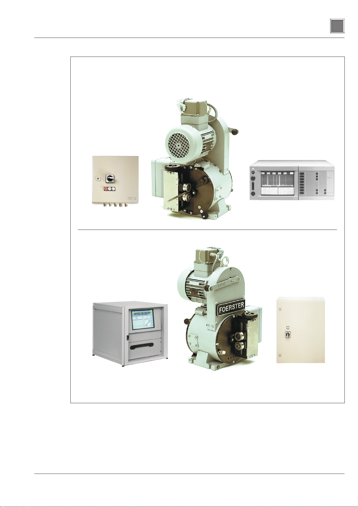
Fig. 2/4Test equipment configuration, CIRCOGRAPH CP (top), CIRCOGRAPH DS (bottom)
2.3 Construction
CIRCOGRAPH DS or DEFECTOMAT CP test electronics and the
connection cables are required for a complete test system, be-
sides the sensor system which scans the test material and gener-
ates the eddy-current signal.
Separate Leaflets:
“CIRCOGRAPH DS System 6.430", Order-No. 163 852 1 and
”CIRCOGRAPH CP 6.412", Order-No. 152 266 3 will inform You
about the according test electronics.
SENSOR SYSTEM Ro 20 P
2.3 Construction Description
2/4 6.460 - 10/2002
i
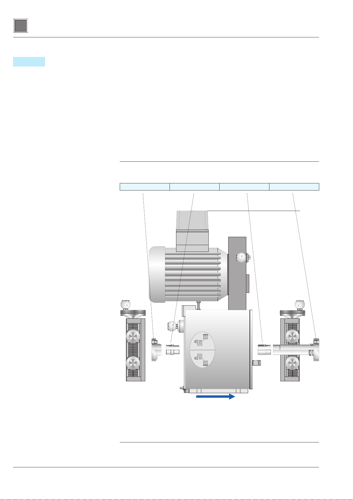
Fig.2/5 CIRCOGRAPH sensor system Ro 20 P
Throughput
preferred direction
Roller guide Ro 20 P left
Ø 4,5 - 20 6.460.01-5001
Ø 1 - 8 6.460.01-5002
Roller guide Ro 20 P right
Ø 4,5 - 20 6.460.01-5011
Ø 1 - 8 6.460.01-5012
Nozzle Holder Outside Nozzle Outside Nozzle Inside Nozzle Holder Inside

The compact CIRCOGRAPH CP test electronics is recommended
in the following cases
§no clearance compensation is required
§a reasonably priced solution is needed
In order to withstand the rough conditions of use, the Ro 20 P has
been designed to be dust-protected, robust and reliable by means
of complex constructional measures such as labyrinth seals and
dirt deflectors.
The chamber surrounding the test zone serves the purpose of
contact and burst protection as well as dust collection. This
chamber is provided with a connection facility for a suction con-
nector for an external extraction system (to be provided by cus-
tomer).
The Ro 20 P sensor system consists of the following compulsory
components:
§rotating head Ro 20 P
§test heads, track width 1.5 – 2.5–5mm
§protective nozzles
The following options are available for adaptation to particular
material conditions:
§roller guides, right, left or on both sides
§precision guide, can be used for 2 to 20 mm
SENSOR SYSTEM Ro 20 P
Description 2.3 Construction
6.460 - 10/2002 2/5
i

2.3.1 Test Heads
The test heads are both the heart of the sensor system and its
most critical components.
They consist of an eddy-current probe with field, measuring and
clearance windings which are installed in a precise mechanical
holder and are connected by means of a highly flexible special
cable with a connection plug.
Due to the high centrifugal forces (acceleration up to 10,000 g!)
and the rough environmental conditions at the testing location,
the test heads are completely cast and can be replaced as a
complete part only.
As already mentioned in the ‘Mode of operation’ section, there is
a mathematical relationship between the number and track width
of the test heads, the rotational speed and the testing speed.
The following table shows these relationships and gives typical
examples for a practical selection:
Maximum testing speed
[m/s] Decreasing
sensitivity to short
flaws Track width BS
[mm] Test head type
0,45 0,9 1,5 N 6.460.01-2015
DF 6.460.03-2015
0,75 1,5 2,5 N 6.460.01-2025
DF 6.460.03-2025
1,5 3,0 5,0 N 6.460.01-2050
DF 6.460.03-2050
n = 9.000 U/min
n = 18.000 U/min
SENSOR SYSTEM Ro 20 P
2.3 Construction Description
2/66.460 -08/2004
i
Test heads
Rotating disc with test heads
2.3.2 Rotating Head Ro 20 P
The rotating head is the main component
of the sensor system. It consists of:
§rotor
§transmitter
§drive
§housing
§rotating head electronics
The test direction can be selected as right
or left (viewed in the throughput direction).
In order to withstand the rough conditions
of use, the Ro 20 P has been designed to
be dust-protected, robust and reliable by
means of complex constructional measures
such as labyrinth seals and dirt deflectors.
Rotor
The rotor consists of a hollow shaft, a rotor
disc and the movable part of the sensor.
The rotor is driven by the motor by means
of a high-power profile flat belt. It is sup-
ported in the housing by two high-speed
bearings.
The high-precision rotating disc for holding
the test heads is fitted on the front side.
A pivot-mounted spiral disc with an actuat-
ing gear and automatic blocking facility is
fitted in the rotating disc for precise and si-
multaneous test head diameter adjustment.
SENSOR SYSTEM Ro 20 P
Description 2.3 Construction
6.460 - 10/2002 2/7
i
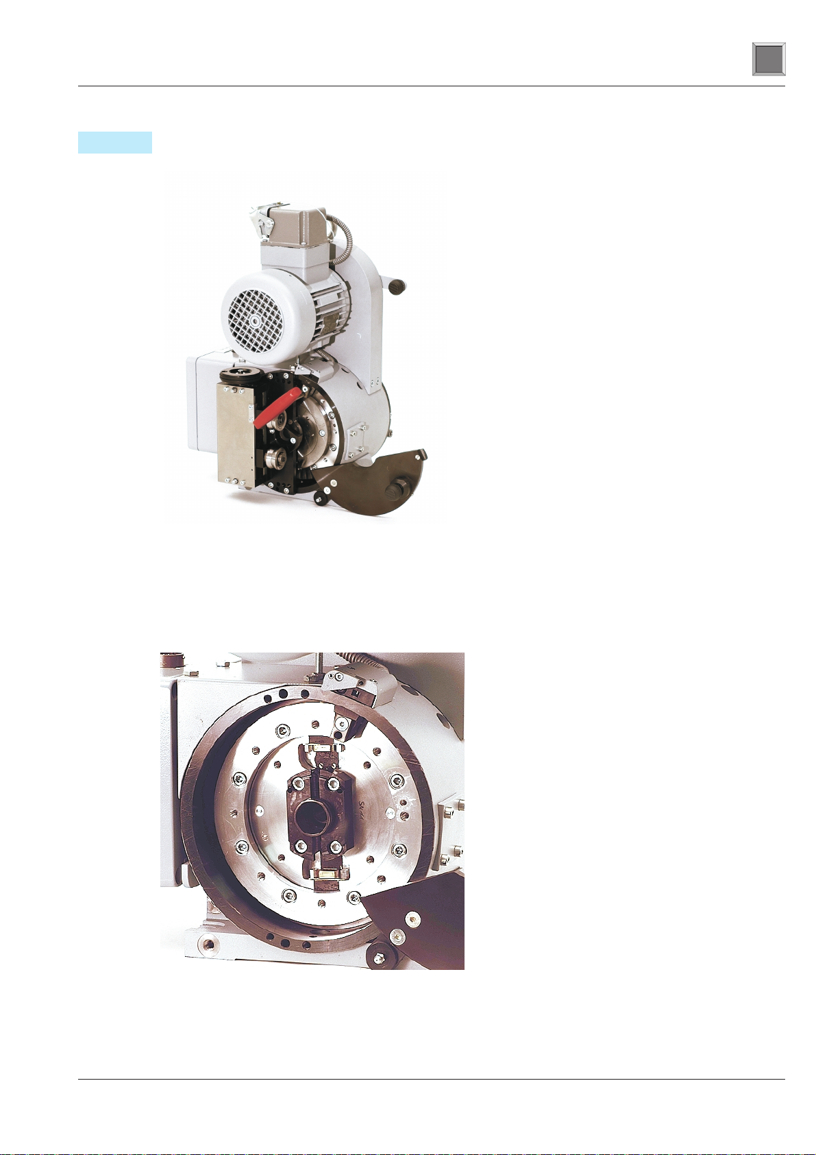
Fig. 2/6Rotiating head Ro 20 P
Fig. 2/7Rotating disc with test heads
View though the opened adjustment side, housing
flange and cover of rotating disc removed

Sensor
Wear-resistant rotating sensor in disc-type construction with a
field sensor, two measuring channels and a clearance channel.
Consisting of a rotor and stator, it transmits the field current for
the rotating probes from the stator to the rotor and, in the oppo-
site direction, transmits the test signal to the test electronics for
evaluation.
Rotating head electronics
The rotating head electronics amplifies the probe signals and the
field current. It is installed in a robust box on the connection side
of the bearing housing to permit ease of maintenance. The cable
to the test electronics is connected using MIL plug connectors.
The drive motor is connected directly using a Harting plug con-
nector.
Drive
SENSOR SYSTEM Ro 20 P
2.3 Construction Description
2/8 6.460 - 10/2002
i
Field 1,2
Channel 2
Channel 1
Clearance
Channel
Rotating
transmitter
Rotier-
übertrager
Preamplifier
Booster
Vorverstärker
Booster
F
M1
M2
A
F
M1
M2
A
FOERSTER CIRCOGRAPH DS 6.430
Fig.2/8Signal path
Table of contents
Other Foerster Accessories manuals


