FOG Enforcer GREASE ENFORCER Manual
GREASE ENFORCER
Copyright ©2017 FOG Enforcer
Toll Free: 1-844-235-0369
E-mail: [email protected]
Online: www.fogenforcer.com
Operation & Maintenance Manual
Mohegan Sun Casino • Uncasville, CT • 8/17
FOG
ENFORCER
88888
88888
88888
88888
88888
88888
88888
88888
88888
8888
8888 8888
8888
©2017 FOG Enforcer All rights reserved • Patented/Patents Pending • Specications subject to change without notice
FOG Enforcer • 2014 Beeler Road • Wilson, NC 27893 • Phone (844) 235-0369 MNLGE 2
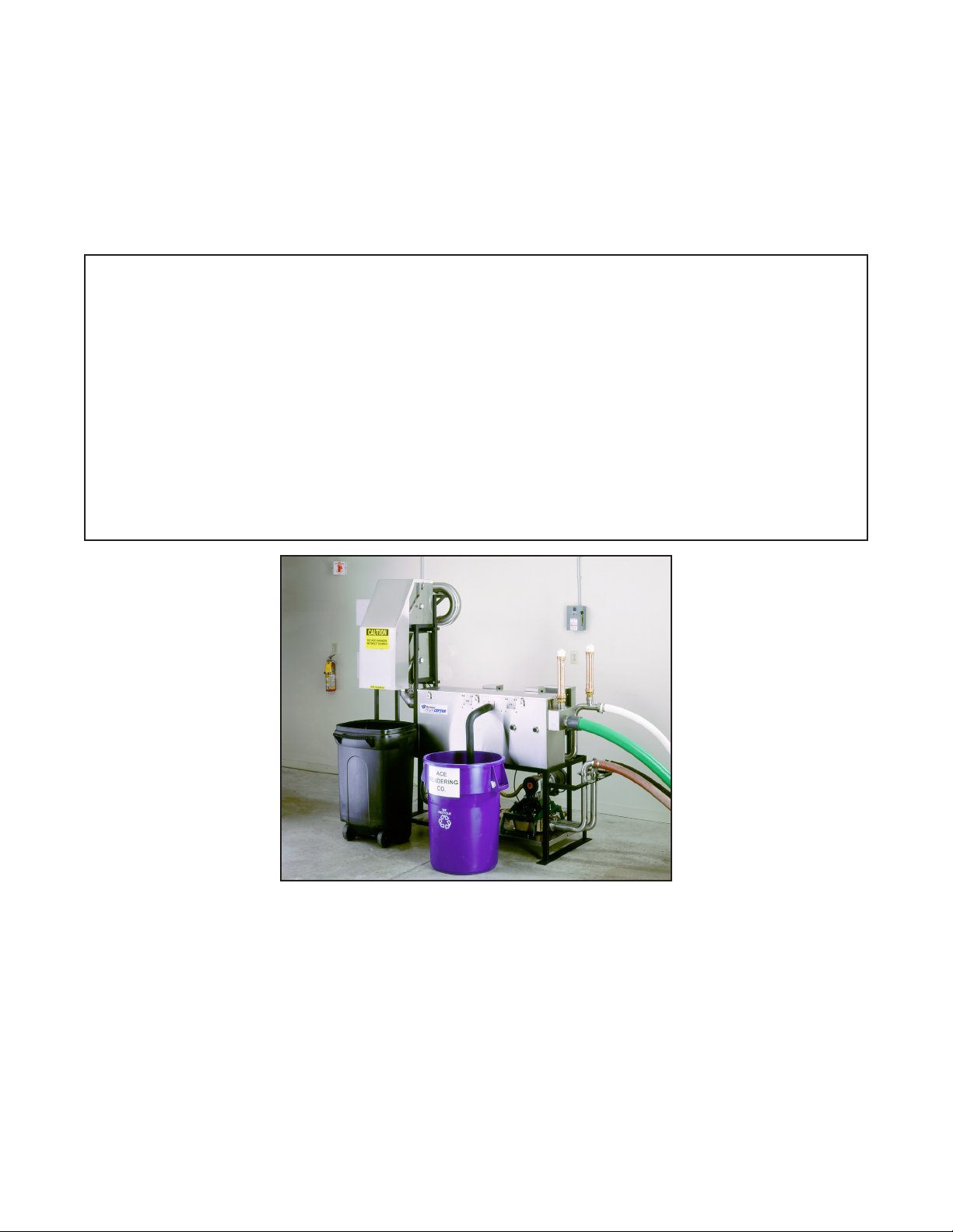
System Overview
DESCRIPTION
The Grease Enforcer was designed for those facilities that want to take charge of their pretreatment system to
meet wastewater discharge limits, solid waste disposal requirements and reduce their risk of exposure to es-
calating disposal costs. You can think of it as having a pumping truck permanently stationed on site providing
daily disposal service, but with an environmentally “friendly” separation operation output of recyclable fats
and oils utilizing the FOG Enforcer component of the Grease Enforcer system, and removal and collection of
landllable “dry” coarse solids utilizing the dual liquids/solids separators.
Incidental solids from kitchen ows are trapped and transferred by the Automatic Solids Transfer System. In
addition to incidental solids, heavy loadings of coarse solids are removed by the dual automatic liquids/
solids separator in the Grease Enforcer system.
The heart of the Grease Enforcer system is the automatic grease and oils separator. This unit removes grease
and oils from wastewater streams. The efcient separation process removes 98% of free-oating grease and
oils, and automatically places them in a container. The oil/grease recovered is virtually water free, and
therefore ready to be sold to a rendering company.
The Grease Enforcer utilizes low shear design diaphragm pumps to transport the grease, oils, and solids from
the remote separator quickly and without emulsification of the grease and oils. The pumps also allow the
specifying engineer to site the Grease Enforcer in the optimum location for convenience, trafc and site
aesthetics, regardless of where the separation tank (or existing grease trap) is located.
The Grease Enforcer has a brain, too, that ensures the operating cycle will perform without a hitch each
time the system operates. The Grease Enforcer system is both environmentally friendly and operation
friendly.
BENEFITS
• Automatically removes coarse solids
• Automatically removes free-oating fats and oils
• Helps reduce BOD levels and associated surcharges and nes
• Reduces operation costs versus paying for pumping service
• Removed dewatered coarse solids are landll ready
• Removed greases/oils are recycle ready for rendering
• Removes up to 900 pounds of fats/oils and 2000 pounds of solids per day
FEATURES
• Rugged corrosion resistant construction
• Easy-access solids removal units
• Reliable automatic operation
• Easy to service modular design
APPLICATIONS
• Restaurants • Casinos • Schools • Bakeries • Cafeterias • Hotels • Nursing Homes
• Universities • Food Processing Plants • Shopping Centers/Malls • Manufacturing Plants
• Commissaries • Airports • Resorts • Hospitals • Institutions • Correctional Facilities
FOG
ENFORCER
GREASE ENFORCER

MNLGE 3
System Specications
Electrical Requirements. . . . . . 230VAC, 3 Phase, 30 Amp.
Eductor Pump Water Supply Requirements**. . 3/4” supply line, 12 GPM
Maximum Grease Removal. . . . . 1744 Pounds/Day
Skimming Rate. . . . . . . . . . 136 Pounds/Hour
Solids Removal Capacity. . . . . . > 2000 pounds/day
Suggested Containment Space. . . 8’ W x 10’ L x 8’ H
Diaphragm Pump Maximum Lift Capability. . . .12 feet from static water level of
separator tank to highest point of diaphragm pump inlet piping. Please contact factory
for higher lift situations.
Services existing sump pit or grease trap daily. Automatically
separates grease and oils into a collection container. Solids are
placed in a separate container.
System Includes:
•FOG Enforcer 75 GPM Automatic Grease Removal Unit
•Two (2) Automatic Solids Separators
•System Control Panel*
•Back-wash Assembly
•Two 1/2 HP (2) diaphragm lift pumps
•Powder Coated Cold-Rolled Steel Support Frame
Grease Enforcer
*Wiring Diagrams & Timing Charts are attached
to Grease Enforcer system.
** Facility is responsible for providing a minimum 3/4”, 12 GPM water supply for
eductor pump operation. FOG Enforcer supplies a 3/4” female connector to
connect to this supply.
©2017 FOG Enforcer All rights reserved • Patented/Patents Pending • Specifications subject to change without notice
FOG Enforcer • 2014 Beeler Road • Wilson, NC 27893 • Phone (844) 235-0369
FOG
ENFORCER
GREASE ENFORCER

FOG Enforcer • 2014 Beeler Road • Wilson, NC 27893 • Phone (844) 235-0369 MNLGE 4
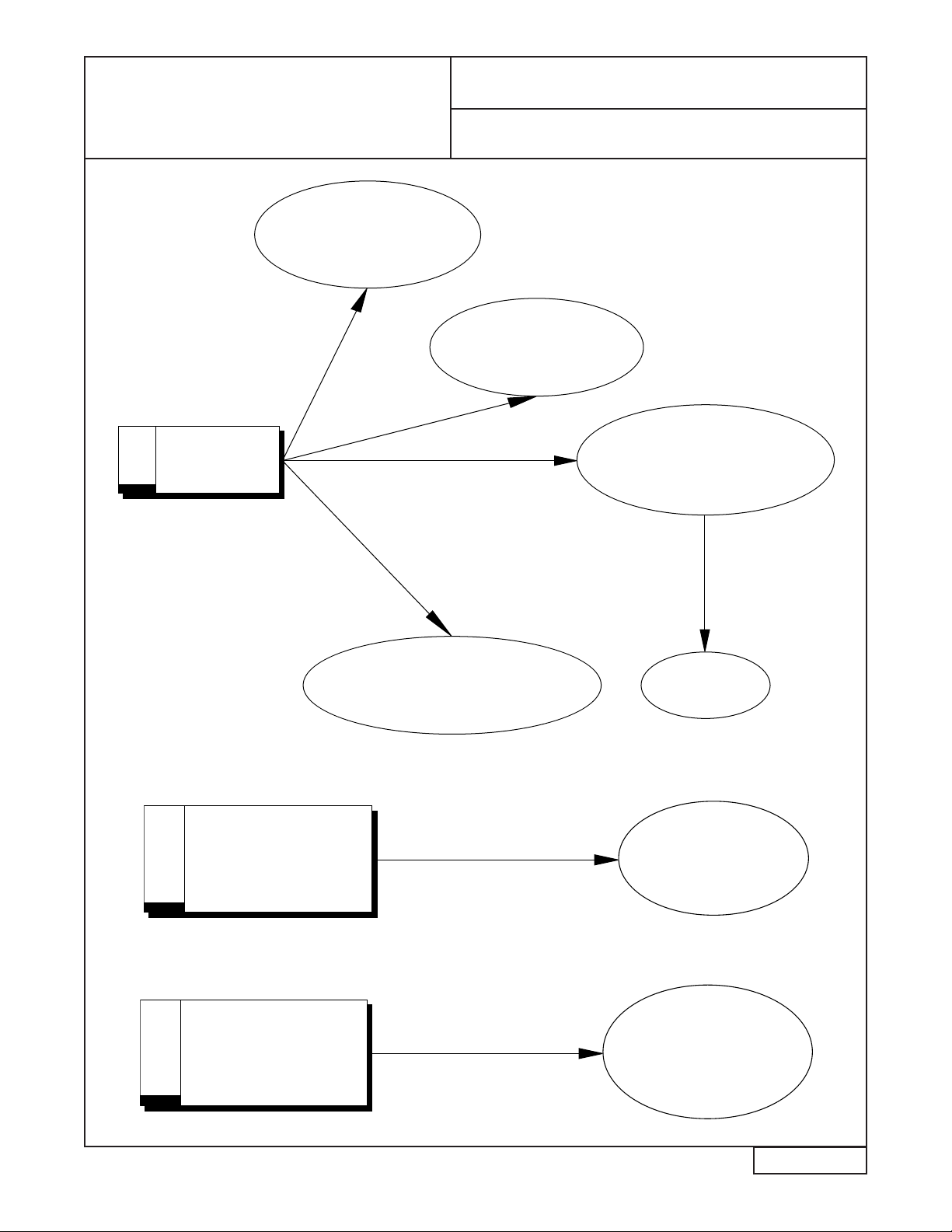
Operation Flowchart
GREASE / OILS
LIFT PUMP
SOLIDS LIFT
PUMP
RECOVERED GREASE / OILS
COLLECTION CONTAINER
AUTOMATIC
SOLIDS
TRANSFER PUMP
MODULE
AUTOMATIC
GREASE / OILS
RECOVERY UNIT
SYSTEM CONTROL
PANEL
INLET FLOW
CLEANED
EFFLUENT FLOW
RE-FLOW LINE
REMOTE
SEPARATION TANK
OUTLET FLOW
RECOVERED COARSE SOLIDS
COLLECTION CONTAINER
COARSE SOLIDS
REMOVAL
UNIT
1. Grease/Oil/Solids bearing ow enters the separator tank from the kitchen. Wastes im-
mediately separate into oating & non-oating (heavier than water) components.
2. Time controller activates Grease Enforcer to begin automatic separation operation. Solids
Cycle
3. Lift pump #2 activates and lifts heavier-than-water solids from the solids hopper
installed in the separator tank. This ow passes through the dual solids removal units,
where coarse solids are separated, dewatered, and emptied into the waste container.
4. The efuent passes through the solids removal units into the FOG Enforecer automatic
grease & oil removal unit, where ne solids are trapped and automatically removed from
the system.
5. The cleaned water passes through the FOG Enforcer and is returned to the separator
tank. Grease Cycle
6. Lift pump #1 activates, lifting accumulated fats, oils and grease from the top 2 - 3” on the
separator tank. Any coarse solids in this ow are separated through the solids removal
component, and any ne solids are removed using the eductor pump on the FOG Enforcer.
7. The fats, oils and grease separate from the efuent in the FOG Enforcer The “cleaned”
efu-ent passes through the FOG Enforcer and is returned to the separator tank.
8. The motors & heaters in the FOG Enforcer activate, skimming the fats, oils & grease out
and depositing them into a grease collection container.
9. The backwash lines activate periodically during the FOG Enforcer skimming cycle to
maintain static liquid level in the Big Dipper unit for optimum skimming efciency.
©2017 FOG Enforcer All rights reserved • Patented/Patents Pending • Specifications subject to change without notice
FOG
ENFORCER
GREASE ENFORCER

FOG Enforcer • 2014 Beeler Road • Wilson, NC 27893 • Phone (844) 235-0369 MNLGE 5
System Control
Grease Enforcer System Control
The Grease Enforcer is designed with the exibility to service a variety of situations. The system
control panel may be easily programmed to provide up to six cleaning cycles per day (most applica-
tions require only one or two daily cycles). Setting the cleaning cycles is a simple process. Inside
the system control panel are two 24-hour timers. Each timer controls a grease cycle and a solids
cycle. The timers in turn are controlled by two selector switches. These selector switches determine
how long each cycle will run for. The selector switches are labelled “Light”, “Medium”, and
“Heavy”. The operator determines the setting according to which setup works best with the
installation/facility. Pushing in one (1) tab on the timer starts the Grease Enforcer cleaning cycle.
Each cleaning cycle can take up to four (4) hours (when the “Heavy” cycle is selected for both the
Grease & Solids cycle). Therefore, a maximum of one tab should be pushed in on either timer each
four hour period.
When the system senses a tab in the “On” position, a pre-programmed logic controller (part
#PLC-1) is activated. The PLC-1 automatically controls timing sequences that ensure the pumps,
heaters, motors and other components needed to provide grease & solids removal operate in the
proper sequence. The PLC-1’s operating cycle is programmed and tested at FOG Enforcer, and
cannot be altered by non-factory personnel. The operating cycle & timing sequences are displayed
on an instruction sheet provided with the system.
The Grease Enforcer is designed to operate with 230 volt three phase power. The system requires 30
amp rated fuses on the supply input. The system has individual internal fusing for each major
component group. Shutting off power to the Grease Enforcer will not harm the internal electronics
or programming.
The system is supplied with a mechanic’s cycle, which enables the Grease Enforcer to operate
at 1/10 normal time. This allows the Grease Enforcer to operate each cycle ten times faster than
normal, allow-ing the operator to check each cycle to ensure full operation. To operate the
mechanic’s cycle, simply press the button in the Control Panel labelled “Mechanic’s Cycle”.
There is also a feature that allows the grease removal unit to drain itself out. The utilize this feature,
push the button labelled “Tank Drain” on the Control Panel when the Grease Enforcer is not actively
en-gaged in either the Grease or Solids cycle. Pushing this button activates the eductor pump,
emptying the grease removal unit. This feature allows for ease of periodic cleaning of the FOG
Enforcer grease removal component included with the system.
Note: This equipment must be installed to comply with all national, state, and local
electrical & plumbing codes for your area. Installation should only be performed by
a qualied, licensed electrician & plumber.
Note: Caution should be used when working with any electrical device. Shutting off
power to the Grease Enforcer will not harm the internal electronics or
programming.
©2017 FOG Enforcer All rights reserved • Patented/Patents Pending • Specifications subject to change without notice
FOG
ENFORCER
GREASE ENFORCER

FOG Enforcer • 2014 Beeler Road • Wilson, NC 27893 • Phone (844) 235-0369 MNLGE 6
Timer Operation
The FOG Enforcer Grease/Solids Timer System offers a great deal of exibility to match the needs of your
kitchen. This improved version incorporates dual 24-Hour Timers coupled with dual selector switches (one each
for solids removal cycle and grease removal cycle). The selector switch provides three settings (heavy,
medium and light) in order to best handle the grease and solids loading from your kitchen operation. If you
have high loadings of solids but a minimal loading of grease, simply set the Solids selector switch at “Heavy”
and the Grease selector switch to “Light,” or vice versa if it’s the other way around.
Grease Cycle Operation:
Three different grease cycles are operator selectable for lift pump running duration of 30 minutes (light), 60
minutes (medium), and 120 minutes (heavy). Grease & oils skimming, solids removal, system ushing and
AST timing reect these settings.
The grease timer (clock) should be set to the desired running time for the grease lift cycles (presumably right
after meals). The grease cycle is programmed to run one cycle and wait for the next “ON” occurrence on the
24-hour timer to run again. The grease cycle takes precedence over the solids cycle - if the solids cycle were
running, it would pause in order to allow the grease cycle to be completed. The solids cycle begins again upon
grease cycle completion.
Solids Cycle Operation:
The frequency of solids lift cycles is operator selectable. Solids lift cycles occur every 120 minutes (light), 60
minutes (medium), or 30 minutes (heavy) as determined by selector switch position. Solids removal, ushing,
and AST operation match frequency with the solids cycle.
The solids timer (clock) should be set to the time when the solids removal process begins and the pins on the
24-hour solids timer are turned to their “ON” position. The solids operation ends when the “OFF” setting is
reached. The solids program begins at the initial “ON” occurrence and repeats (loops) until the timer reaches
the “OFF” settings.
©2017 FOG Enforcer All rights reserved • Patented/Patents Pending • Specifications subject to change without notice
7
32
1
4
5
AM
7
8
9
10
11
12
1
234
5
PM
8
9
10
11
12
12
6
7
9 3
Time-of-day
indicator point
Tabs not punched in
indicate “OFF” setting
Tabs punched in indicate
“ON” setting
TO SET TIMER:
1. Push on/off tabs on the outer ring of timer
inwardinto dial at desired“ON” times. Only
one tab is needed to start the Grease Enforcer
cycle.
2. TurndialCLOCKWISE one ormore
complete revolutionsuntilthepresenttime is
alignedwith the time-of-day indicator point.
3. Always set one cycle timer to run at least 2
hours after the previous cycle. The “Heavy”
setting for both the grease & solids cycle runs
for 2 hours. The grease & solids cycles cannot
run simultaneously.
FOG
ENFORCER
GREASE ENFORCER

©2017 FOG Enforcer All rights reserved • Patented/Patents Pending • Specifications subject to change without notice
FOG Enforcer • 2014 Beeler Road • Wilson, NC 27893 • Phone (844) 235-0369 MNLGE 7
Installation Schematic
Note: The remote separator tank is not provided by FOG Enforcer.
The remote separator tank will be designed by the engineer to be a passive grease trap.
Grease Enforcer
LIFT PUMPS
DUAL
COARSE SOLIDS
REMOVAL SYSTEM
GREASE/OILS
RECOVERY UNIT WITH
AUTOMATIC SOLIDS
TRANSFER
CONNECTION
FOR FACILITY
VENT
COARSE SOLIDS
SUCTION PIPE
FLOATING GREASE/OILS
PICK-UP SUCTION PIPE
STATIC
WATER
LEVEL
ACCESS COVER
3” REFLOW LINE
REFLOW
LINE
12” RACEWAY FOR HOSES
TO SEPARATOR TANK
EFFLUENT FLOW FROM
KITCHEN
2” AUTOMATIC
SOLIDS
TRANSFER
DISCHARGE LINE
2” SOLIDS TRANSFER
DISCHARGE LINE
12” RACEWAY FOR HOSES
TO SEPARATOR TANK
GROUND
LEVEL
FOR FURTHER EQUIPMENT
DETAIL SEE SYSTEM PRODUCT
DIMENSION AND SPECIFICATION
PAGES
CLEANED
EFFLUENT
FLOW
DISCHARGE
SOLIDS HOPPER
REMOTE SEPARATOR TANK
HOT WATER
CONNECTION
3/4” FEMALE
CONNECTOR
CONTROL
PANEL
GREASE/OILS
SUCTION PIPE
TYPICAL SITE LAYOUT FOR FOG ENFORCER MODEL
GREASE ENFORCER WITH DUAL
COARSE SOLIDS REMOVAL MODULES SERVICING
IN-GROUND CONCRETE SEPARATOR
NOTES:
1. 12” RACEWAY CONDUITS USE 22 DEGREE FITTING TO MAKE
ANY RADIUS.
2. THE REMOTE SEPARATOR TANK AND ACCESS COVER ARE NOT
PROVIDED BY FOG ENFORCER.
3. THE FACILITY MUST SUPPLY A MINIMUM 3/4”, 12 GPM WATER
SUPPLY FOR THE OPERATION OF THE EDUCTOR PUMP.
FOG RNFORCER PROVIDES A 3/4” FEMALE CONNECTOR TO
CONNECT TO THIS WATER SUPPLY.
COARSE
SOLIDS
SUCTION PIPE
FOG
ENFORCER
GREASE ENFORCER
FOG Enforcer • 2014 Beeler Road • Wilson, NC 27893 • Phone (844) 235-0369 MNLGE 8
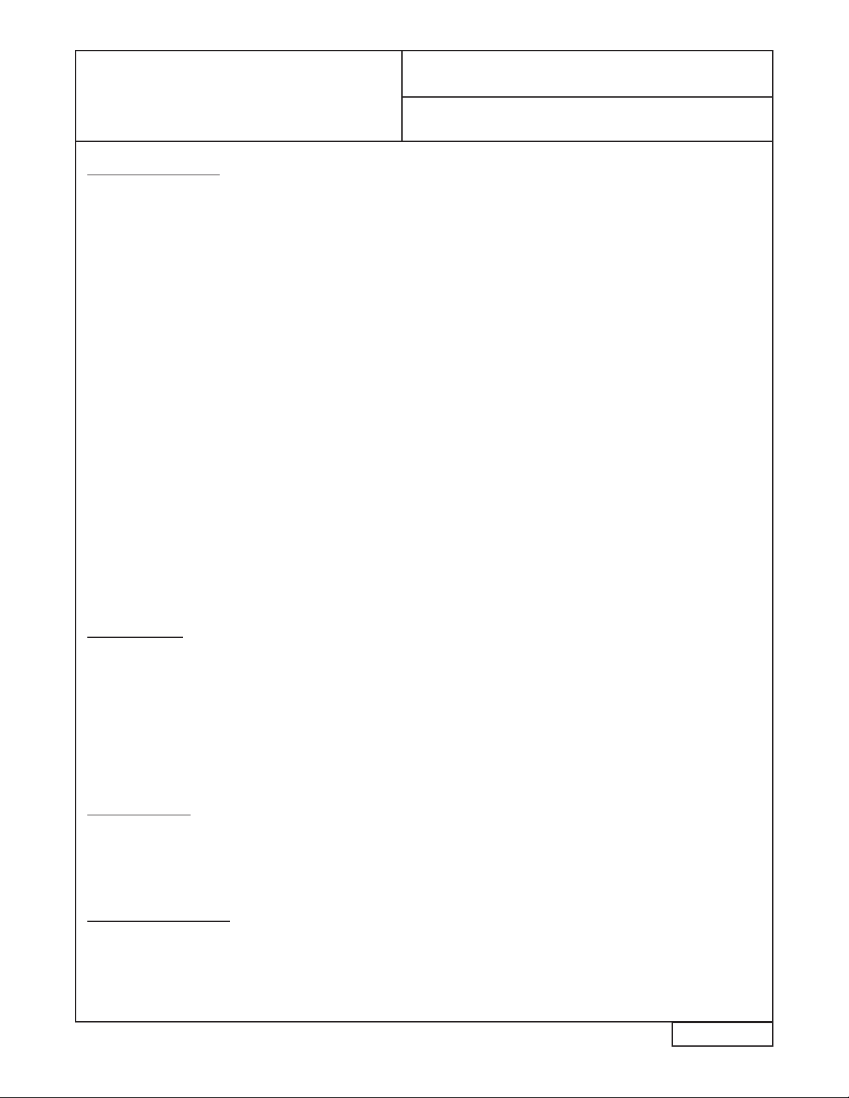
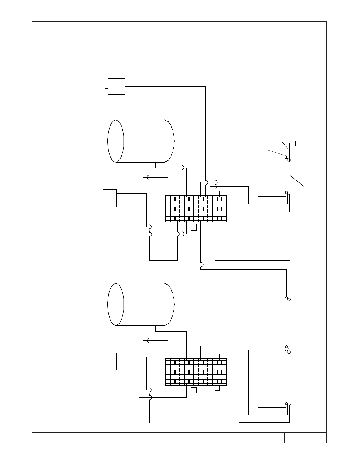
Side Views
Grease Enforcer
SYSTEM CONTROL
PANEL
GREASE/OILS
RECOVERY UNIT WITH
AUTOMATIC SOLIDS
TRANSFER
DUAL COARSE SOLIDS REMOVAL
SYSTEMS
2” SOLIDS TRANSFER
DISCHARGE LINE
COARSE SOLIDS
SUCTION PIPE FROM
BELOW GROUND SEPARATOR
12” RACEWAY CONDUIT
LIFT PUMPS
GREASE/OILS SUCTION PIPE FROM
BELOW GROUND SEPARATOR
101”
86”
SOLIDS REMOVAL
MOTOR
ENCLOSURES
3”
REFLOW
LINE
2” SOLIDS TRANSFER
DISCHARGE LINE
CONNECTION FOR
FACILITY VENT
SIDE VIEW PUMP/
CONTROL SIDE
SIDE VIEW COLLECTION SIDE
©2017 FOG Enforcer All rights reserved • Patented/Patents Pending • Specifications subject to change without notice
OUTLET
OUTLET
3”
REFLOW
LINE
COARSE SOLIDS
COLLECTION
CONTAINER
GREASE/OILS
COLLECTION
CONTAINER
HOT WATER
CONNECTION
3/4” FEMALE
CONNECTOR
FOG
ENFORCER
GREASE ENFORCER

©2017 FOG Enforcer All rights reserved • Patented/Patents Pending • Specifications subject to change without notice
FOG Enforcer • 2014 Beeler Road • Wilson, NC 27893 • Phone (844) 235-0369 MNLGE 9
Top View
Grease Enforcer
FOG ENFORCER
GREASE/OILS
RECOVERY UNIT
12” RACEWAY
CONDUIT
2” SOLIDS TRANSFER
RETURN LINE FROM
OUTLET OF REMOTE
SEPARATOR TANK
BACKFLUSH
LINE
COARSE SOLIDS
SUCTION PIPE FROM
BELOW GROUND
SEPARATOR
GREASE/OILS SUCTION PIPE FROM
BELOW GROUND SEPARATOR
GREASE/OILS
COLLECTION
CONTAINER
COARSE SOLIDS
COLLECTION CONTAINER
TOP VIEW
113”
65”
101”
84”
DUAL
COARSE
SOLIDS
REMOVAL
SYSTEM
CONTROL
PANEL
MINIMUM FOOTPRINT
3” REFLOW LINE
FOG
ENFORCER
GREASE ENFORCER
©2017 FOG Enforcer All rights reserved • Patented/Patents Pending • Specifications subject to change without notice
FOG Enforcer • 2014 Beeler Road • Wilson, NC 27893 • Phone (844) 235-0369 MNLGE 10
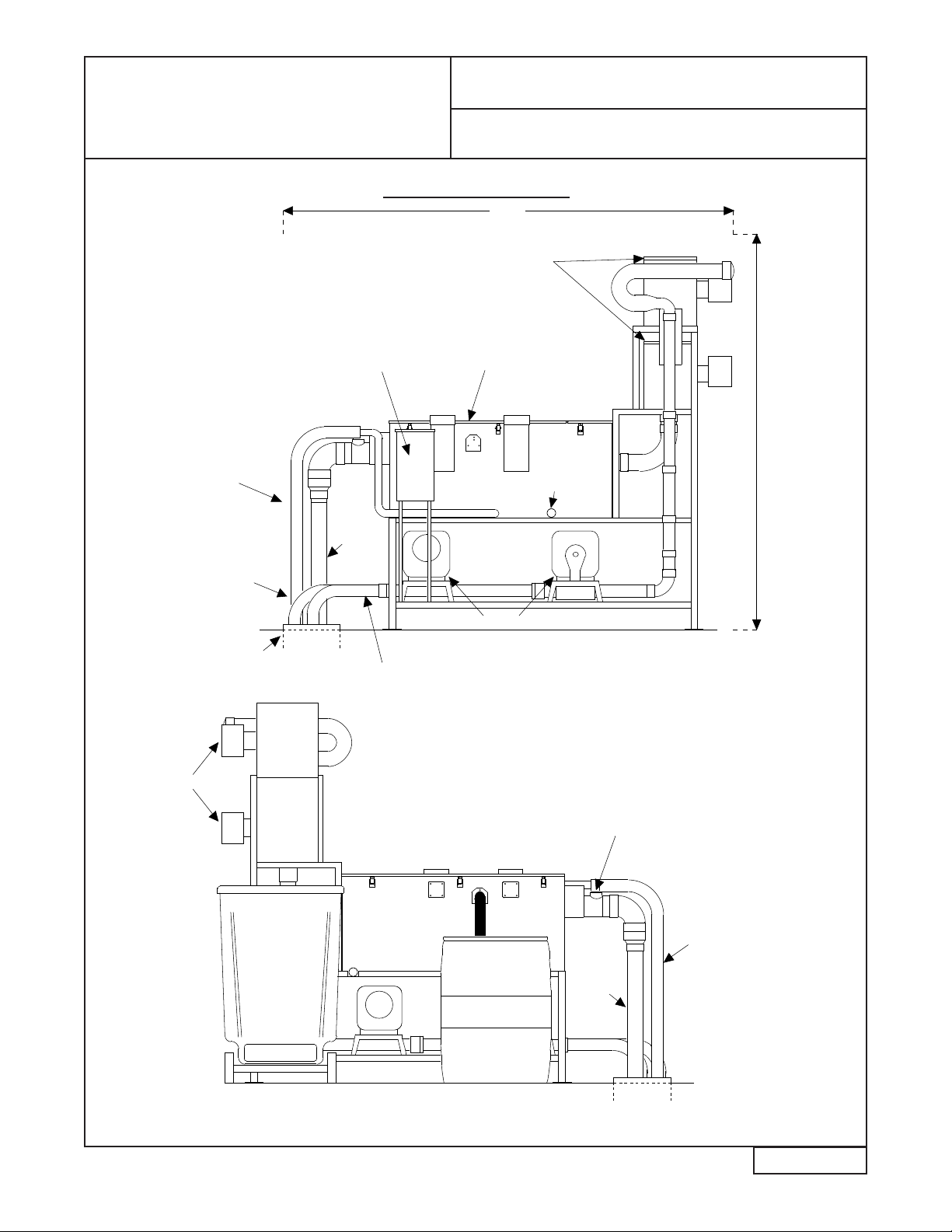
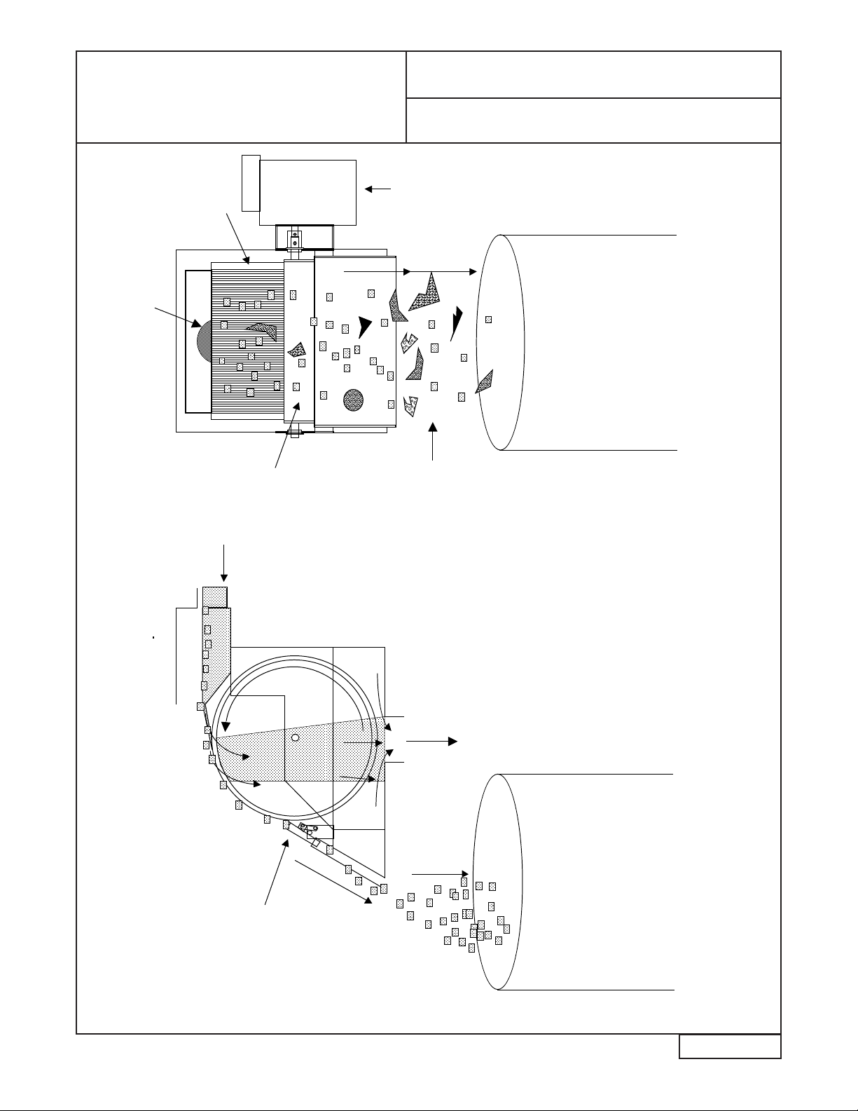
Solids Removal Operation
Solids Removal Operation Schematic & Part Identication*
Inlet Plenum
Screen
Scraper
Screened
Solids Drop
Into Waste
Container
Flow From
Separator
INLET Screen
Scraper
Screened
Solids Drop
Into Waste
Container
INLET
Drum
Screen
Motor
Housing
Solids
Collection
Container
Solids
Collection
Container
Front ViewSide View
Screened Flow
Enters The FOG
Enforcer
Automatic Grease
& Oils Removal
Unit
*These Systems WILL NOT OPERATE unless the cover is attached
FOG
ENFORCER
GREASE ENFORCER
FOG Enforcer • 2014 Beeler Road • Wilson, NC 27893 • Phone (844) 235-0369 MNLGE11
DAILY
Empty grease and solids collection containers. Wash containers if necessary.
WEEKLY
Check wheel wiper blades for build-up of ne solids. If build-up is present, wipe or spray
clean.
Inspect the dual Big Flipper® coarse solids removal screen for ne solids buildup. It may
easily be sprayed with hot water or wiped clean.
The bottom of the Big Dipper tank should be checked for ne solids accumulation. If
build-up of ne solids has accumulated, solids should be removed by stirring the bottom
with a long handled spatula or using a “wet vac” or by using the “Tank Drain” sequence.
Inspect the grease outlet sump for build-up of congealed fats or ne solids. Wipe off any
accumulation.
QUARTERLY
Grease the drive cam on each of the Grease Enforcer’s diaphragm lift pumps. There is a
grease tting on the drive cam’s housing. (Please see Page 26 “Grease Enforcer Diaphragm
Pump Identication”)
Check hose connections (quick disconnect) for tight t.
ANNUALLY
Replace FOG Enforcer’s wiper blades (part # PB-3).
Inspect FOG Enforcer Wheel Drive Sprockets (part # WDS-1) for wear. Replace if
necessary.
Check FOG Enforcer’s motor-to-wheel drive shaft coupling (part # NSC-1) for slippage.
Re-place if necessary.
Check lift pump diaphragms for wear or leaks.
Make sure GOPA assembly is secure and in place. (Please see Page 10 “Grease/Oils Pickup
Assembly”)
©2017 FOG Enforcer All rights reserved • Patented/Patents Pending • Specifications subject to change without notice
Maintenance Instructions
FOG
ENFORCER
GREASE ENFORCER

©2017 FOG Enforcer All rights reserved • Patented/Patents Pending • Specifications subject to change without notice
FOG Enforcer • 2014 Beeler Road • Wilson, NC 27893 • Phone (844) 235-0369 MNLGE 12
Wait Seven Minutes
No grease
collected
in
container
Make sure oily
water is pumped
into grease
removal unit
Check lift pump
hose connections
for leaks
Check lift pumps for
leaks
Remove
grease
removal unit
lid
Clean wiper blades,
collection trough,
and outlet hose
Make sure wiper
blades are
attached properly
Replace wiper
blades when
worn
Set
Superceptor
timer to "On"
position
Hold down
safety
switch
Make sure
skimmer
wheel turns
If skimmer motor
does not activate,
motor must be
replaced
If skimmer motor
activates, make
sure safety switch is
fully depressed
when lid is fastened
to unit
Check
heater
assembly
If heater does not
begin to feel warm in
15 minutes, heater
must be replaced
Make sure GOPA
assembly is 1.5" to 2"
below static water level
in separation tank
Grease Enforcer Troubleshooting
FOG
ENFORCER
GREASE ENFORCER
©2017 FOG Enforcer All rights reserved • Patented/Patents Pending • Specifications subject to change without notice
FOG Enforcer • 2014 Beeler Road • Wilson, NC 27893 • Phone (844) 235-0369 MNLGE 13
Excessive water
observed in grease
collection unit
Check timer for
excessive
"On"cycles
Objectionable
odor
Make sure grease/oil
is being properly
skimmed from unit
Check for excessive
sediment buildup in
bottom of unit
Empty solids container
and/or grease collector
more frequently
Clean after
emptying
If installed, spray surface of
solids removal screen with
hot water
Grease Enforcer Troubleshooting
No solids collected in
collection container
Ensure cover is
securely in place
over solids
removal units
FOG
ENFORCER
GREASE ENFORCER
©2017 FOG Enforcer All rights reserved • Patented/Patents Pending • Specifications subject to change without notice
FOG Enforcer • 2014 Beeler Road • Wilson, NC 27893 • Phone (844) 235-0369 MNLGE 14
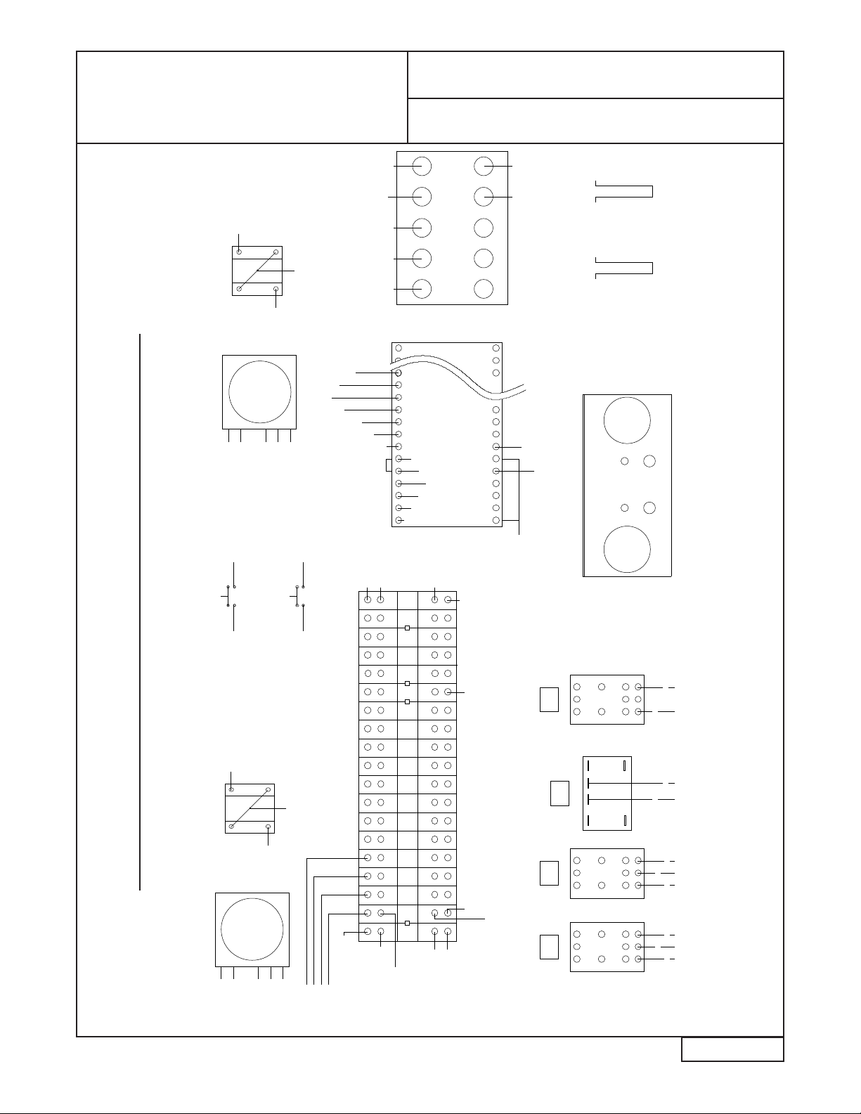
Control Panel Wiring Diagram
Grease Enforcer Control Panel Wiring Diagram
C
COIL
NC
NO
R1
AB
C
A
NO
NC
COIL
B
R2 R4
C
A
NO
NC
COIL
B
STRAIN-RELIEF LAYOUT
(TOP VIEW)
PLC CONTROLLER
INPUTS
OUTPUTS
BACKFLUSH
GREASE REMOVAL UNIT
GRD GRD
1
BLK
2
RED
3
BLUE
J JJ
F1
6A
F2
6A
F3
6A
F4
2A
F5
2A
4 5 6 7 8 8
F1 F2 F3
R3
J
7 7 9
PUMP #1
GREASE LIFT PUMP #2
SOLIDS LIFT
SOLIDS
SEPARATOR
GREASE REMOVAL
UNIT
4 5 6 4 5 6 7 8
7 7 7PLC0 PLC1 PLC5
8
9
PLC IN 0
R3
R3
F4 F5
1
4 F1
R1
R2
2
5
R2
F2
R1
6
3
R2
F3
R1
2
7 F4
R3A
R4A R4C
TIM 3
8F5
PLC
TIM
R4C
PLC
OUT
+24
PLC
PUMP #1
PUMP #2
BLACK
RED
BLUE
L3
L2
L1
GROUND GREEN
PLC
12
7PLC2
7
PLC IN 1
9
8
3
4 3
4
H L
M
SELECTOR SWITCH
PLC IN 6
PLC IN 5
9
TIMER
GREASE CYCLE CONTROLS
SOLIDS CYCLE CONTROLS
SELECTOR SWITCH
PLC IN 2
7
9
1 DAY
24 HOUR
TIMER
PLC IN 4
8
TIMER
PLC IN 3
4 3
9
H
3
L
4
M
7 PLC 4
TIM
TIM
GREASE CONT
SOLIDS CONT
MECH CYCLE
R1A R2A
PLC
MTC SWITCH
MECHANIC'S TIMING CYCLE
(MOMENTARY CONTACT)
PLC 3
MDC SWITCH
MECHANIC'S DRAINING CYCLE
(MOMENTARY CONTACT)
8
MDC
CONTROL PANEL LAYOUT
(TOP VIEW)
GREASE
TIMER
SOLIDS
TIMER
MTC MDC
SOLIDS
SELECTOR
GREASE
SELECTOR
PLC 3
7
1 DAY
24 HOUR
TIMER
BACKWASH
AST
PUMP
SOLIDS
SEPARATOR
SOLIDS
SOL VLV
BACKWASH
VLV
PUMP #1
(GREASE)
PUMP #2
(SOLIDS)
POWER
INPUT
BACKWASH SOLIDS
SEPARATOR
AST
SOLIDS
PUMP
GREASE
REMOVAL
UNIT
BLACK
RED
WHITE BLACK
RED
WHITE
BLACK
WHITE
BLACK
WHITE
SGBA76543210COM1
OUT
COM1
OUT
R1 R2 R3 R4
SOLIDS
SOL VLV/MDC
BACKWASH
VLV
654321015
87 9GRD
MECH
SW.
GREASE
TIMER
SOLIDS
TIMER
L. SOLIDS
SW.
LINE
H. GREASE
SW.
L. GREASE
SW.
NEUTRAL
GROUND
+24VDC OUT
0VDC OUT
DC IN COM
FOG
ENFORCER
GREASE ENFORCER

©2017 FOG Enforcer All rights reserved • Patented/Patents Pending • Specifications subject to change without notice
FOG Enforcer • 2014 Beeler Road • Wilson, NC 27893 • Phone (844) 235-0369 MNLGE 15
Grease Removal
Component Wiring Diagram
Wiring Diagram For FOG Enforcer Grease & Oils Removal Unit
MOTOR
BLUE
BLUE
RUN
CAPACITOR
PUSH-BUTTON
SWITCH
MOTOR/HEATER ENCLOSURE
MOTOR
BLUE
BLUE
RUN
CAPACITOR
PUSH-BUTTON
SWITCH
BL
RED
BLACK
RED
WHITE
9
8
10
4
5
6
2
G
1
3
JUMPER
7
WHITE
DISTRIBUTION
BLOCK
G
THERMOSTAT
HEATER
RED
BLACK
CONNECTING CORD
WHITE
BLACK
RED
9
8
WH
4
6
5
2
G
1
3
7
HEATER
THERMOSTAT
BLACK
WHITE
GRED
BLANK
GROUND
RED
WHITE
BL
JUMPER
GROUND
BLANK
DISTRIBUTION
BLOCK
10
MOTOR/HEATER ENCLOSURE
G
R3
R3
GREEN
BLACK
GREEN
GREEN
TO CONTROL PANEL
WHITE
WHITE
BLACK BLACK
FOG
ENFORCER
GREASE ENFORCER
©2017 FOG Enforcer All rights reserved • Patented/Patents Pending • Specifications subject to change without notice
FOG Enforcer • 2014 Beeler Road • Wilson, NC 27893 • Phone (844) 235-0369 MNLGE 16
Coarse Solids Removal Wiring
Diagram
CONTROL PNL
RELAY 4
BLACK
WHITE
GREEN
MOTOR
BLACK
RED
WHITE
BLUE
BLUE
RUN
CAPACITOR
9
10
7
5
6
3
1
2
4
8
G
DISTRIBUTION
BLOCK
G
BLACK
GROUND IN SYSTEM
CONTROL PANEL
BLANK
JUMPER
GREEN
208-240 VAC POWER CORD
FROM SYSTEM CONTROL PANEL
WHITE
LOWER UNITUPPER UNIT
WHITE
RED
BLACK
BLANK
JUMPER
10
9
G
G
8
7
6
5
4
3
2
1
BLUE
BLUE
GROUND
DISTRIBUTION
BLOCK
WHITE
BLACK
RUN
CAPACITOR
MOTOR
GREEN
BLUE
BLACK
LID
INTERLOCK
SWITCH
CONTROL PNL
RELAY 4
BLACK
GREEN
BLACK
Wiring Diagram For Dual Coarse Solids Removal Units
UPPER UNIT
LOWER UNIT
FOG
ENFORCER
GREASE ENFORCER
©2017 FOG Enforcer All rights reserved • Patented/Patents Pending • Specifications subject to change without notice
FOG Enforcer • 2014 Beeler Road • Wilson, NC 27893 • Phone (844) 235-0369 MNLGE 17
Miscellaneous Component Wiring
Diagrams
BACKWASH SOLENOID
D/B POSITION 7
PLC OUTPUT 4
BLACK
WHITE
GREEN
SOLIDS TRANSFER SOLENOID
FROM CONTROL PANEL
208-240 VAC LEAD
GREEN
PANEL
GROUND IN CONTROL
GREEN
B/D POSITION 7
PLC OUTPUT 3
BLACK
WHITE
FOG
ENFORCER
GREASE ENFORCER
©2017 FOG Enforcer All rights reserved • Patented/Patents Pending • Specifications subject to change without notice
FOG Enforcer • 2014 Beeler Road • Wilson, NC 27893 • Phone (844) 235-0369 MNLGE 18
Grease Timing Chart
GREASE ENFORCER GREASE TIMING CHART
Not To Be Altered By Non-Factory Personnel
PRE-PROGRAMMED OPERATION SEQUENCE STEPS. EACH STEP IS EQUAL TO 2 MINUTES.
SEQUENCE BEGINS WHEN 24-HOUR TIME CONTROLLER OUTPUT SWITCHES FROM OFF TO ON (INPUT
#1) AND STOPS WHEN THE CYCLE IS COMPLETE. POSITION OF THE GREASE SELECTOR SWITCH DE-
TERMINES THE LENGTH OF TIME THAT GREASE IS REMOVED FROM THE TRAP.
0 2 4 6 810 12 14 16 18 20 22 24 26 28 30 32 34 36 38 40 42 44 46 48 50
OFF
ON
GREASE/OILS LIFT PUMP
SOLIDS TRANSFER PUMP
BACKWASH VALVE
SOLIDS SEPARATOR UNIT
INPUT #0
INPUT #1
OUTPUT #0
OUTPUT #2
OUTPUT #3
OUTPUT #4
OUTPUT #5
GREASE REMOVAL UNIT
INPUT #5
INPUT #6
"LIGHT" GREASE SELECTOR SWITCH POSITIONS SHOWN
MECHANIC'S CYCLE
(SHORT CYCLE)
TIME CONTROLLER INPUT
(GREASE TIME CLOCK)
LIGHT GREASE
(SELECTOR SWITCH)
HEAVY GREASE
(SELECTOR SWITCH)
FOG
ENFORCER
GREASE ENFORCER

©2017 FOG Enforcer All rights reserved • Patented/Patents Pending • Specifications subject to change without notice
FOG Enforcer • 2014 Beeler Road • Wilson, NC 27893 • Phone (844) 235-0369 MNLGE 19
Grease Timing Chart
GREASE ENFORCER GREASE TIMING CHART
Not To Be Altered By Non-Factory Personnel
PRE-PROGRAMMED OPERATION SEQUENCE STEPS. EACH STEP IS EQUAL TO 2 MINUTES.
SEQUENCE BEGINS WHEN 24-HOUR TIME CONTROLLER OUTPUT SWITCHES FROM OFF TO ON
(INPUT #1) AND STOPS WHEN THE CYCLE IS COMPLETE. POSITION OF THE GREASE SELECTOR
SWITCH DETERMINES THE LENGTH OF TIME THAT GREASE IS REMOVED FROM THE TRAP.
0 2 4 6 810 12 14 16 18 20 22 24 26 28 30 32 34 36 38 40 42 44 46 48 50 52 54 56 58 60 62 64 66 68 70
OFF
ON
GREASE/OILS LIFT
PUMP
SOLIDS TRANSFER
PUMP
BACKWASH VALVE
SOLIDS SEPARATOR
UNIT
INPUT #0
INPUT #1
OUTPUT #0
OUTPUT #2
OUTPUT #3
OUTPUT #4
OUTPUT #5
GREASE REMOVAL
UNIT
INPUT #5
INPUT #6
"MEDIUM" GREASE SELECTOR SWITCH POSITIONS SHOWN
HEAVY GREASE
(SELECTOR SWITCH)
LIGHT GREASE
(SELECTOR SWITCH)
TIME CONTROLLER INPUT
(GREASE TIME CLOCK)
MECHANIC'S CYCLE
(SHORT CYCLE)
FOG
ENFORCER
GREASE ENFORCER
©2017 FOG Enforcer All rights reserved • Patented/Patents Pending • Specifications subject to change without notice
FOG Enforcer • 2014 Beeler Road • Wilson, NC 27893 • Phone (844) 235-0369 MNLGE 20
Grease Timing Chart
GREASE ENFORCER GREASE TIMING CHART
Not To Be Altered By Non-Factory Personnel
PRE-PROGRAMMED OPERATION SEQUENCE STEPS. EACH STEP IS EQUAL TO 2 MINUTES.
SEQUENCE BEGINS WHEN 24-HOUR TIME CONTROLLER OUTPUT SWITCHES FROM OFF TO ON
(INPUT #1) AND STOPS WHEN THE CYCLE IS COMPLETE. POSITION OF THE GREASE SELECTOR
SWITCH DETERMINES THE LENGTH OF TIME THAT GREASE IS REMOVED FROM THE TRAP.
0 2 4 6 810 12 14 16 18 20 22 24 26 28 30 32 34 36 38 40 42 44 46 48 50 52 54 56 58 60 62 64 66 68 70
OFF
ON
BACKWASH VALVE
SOLIDS SEPARATOR UNIT
INPUT #0
INPUT #1
OUTPUT #0
OUTPUT #2
OUTPUT #3
OUTPUT #4
OUTPUT #5
GREASE REMOVAL
UNIT
78767472 908886848280
LIGHT GREASE
(SELECTOR SWITCH)
INPUT #5
INPUT #6
"HEAVY" GREASE SELECTOR SWITCH POSITIONS SHOWN
MECHANIC'S CYCLE
(SHORT CYCLE)
TIME CONTROLLER INPUT
(GREASE TIME CLOCK)
HEAVY GREASE
(SELECTOR SWITCH)
GREASE/OILS LIFT PUMP
SOLIDS TRANSFER PUMP
FOG
ENFORCER
GREASE ENFORCER
Table of contents


