WEDGELOCK I-LOCK COUPLER User manual

Parts & Service 28/06/2009 902-001-2 Rev 0 1 of 28

Parts & Service 28/06/2009 902-001-2 Rev 0 2 of 28
*(Refers to Installation Manual page reference)
1 Remove Bucket if attached to the excavator dipper arm.
2 Install Quick Coupler using the carrier machine’s original dipper and linkage pins (8, 9, 10)*.
3 Once mounted, rotate coupler through its full range of movement and check clearances around
coupler and dipper arm (10)*.
4 Begin routing hoses from coupler to the dipper manifold on the dipper arm to determine hose
routing and dipper manifold positioning (11, 13)*.
5 Position dipper arm hoses, install hose clamps and connect hoses to dipper manifold as labelled
(11, 13)*.
6 Position boom hoses, install hose clamps and join unions. Ensure all moving joints are fitted with
abrasive sleeve supplied (14)*.
7 After hose routing is completed, it will be easy to determine the best/final mounting location for
the coupler control valve (12, 15)*.
8 Route hoses from valve ports to labelled hoses on boom and join with unions (15)*.
9 Locate and connect pressure line from test port on pump to “P” port on valve (15)*.
10
Locate and connect hose form tank to return line to “T” port on valve (15)*.
11
Locate mounting position for I-LOCK control switch in cab (16)*.
12
Route electrical harness from DIN connectors on valve to switch harness and attach positive and
negative leads (16)*.
13
Test coupler to ensure all functions are working properly. (Please refer to Operators Manual)*.

Parts & Service 28/06/2009 902-001-2 Rev 0 3 of 28
PAGE
FRONT COVER / REFERENCE CARD 1
CONTENTS 3
INTRODUCTION 4
CONTACTS 5
SECTION 1: INSTALLATION GUIDE LINES
1.0 CHECK LIST 6
SECTION 2: PRECAUTIONS
2.0 SAFETY PRECAUTIONS 7
2.1 WELDING PRECAUTIONS 7
SECTION 3: COUPLER INSTALLATION
3.0 SAFETY DURING COUPLER INSTALLATION 8
3.1 COUPLER ORIENTATION 8
3.2 REMOVING THE EXISTING BUCKET 9
3.3 FITTING THE COUPLER (LINK PIN) 9
3.4 FITTING THE COUPLER (DIPPER PIN) 10
SECTION 4: HYDRAULIC KIT INSTALLATION
4.0 JUNCTION MANIFOLD POSITION 11
4.1 FITTING THE JUNCTION MANIFOLD BLOCK 11
4.2 THE I-LOCK CONTROL VALVE 12
4.3 INSTALLING THE CONTROL VALVE 12
4.4 HOSE ROUTING 13
4.5 HOSE ROUTING – DIPPER ARM 13
4.6 HOSE ROUTING – BOOM 14
4.7 HOSE ROUTING – BOOM TO VALVE 15
4.8 HOSE ROUTING VALVE TO PUMP / TANK 15
SECTION 5: ELECTRICAL INSTALLATION
5.0 ELECTRICAL INSTALLATION 16
SECTION 6: SCHEMATICS
6.0 HYDRAULIC SCHEMATIC 17
6.1 ELECTRICAL SCHEMATIC 17
SECTION 7: FINISH & TEST
7.0 FINISH & TEST 18
SECTION 8: TORQUE CHARTS
8.0 TORQUE CHART – METRIC BOLTS 19
8.1 TORQUE CHART – JIC CONNECTORS 19
SECTION 9: INSTALL KITS
9.0 HOSE KIT, I-LOCK 130 20
9.1 HOSE KIT, I-LOCK 170, 210, 270 21
9.2 HOSE KIT, I-LOCK 320 22
9.3 HOSE KIT, I-LOCK 450 23
9.4 HOSE KIT, I-LOCK 750 24
9.5 HOSE KIT, I-LOCK 1000 25
SECTION 10: WARRANTY
10.0 WARRANTY 26
SECTION 11: WARRANTY REGISTRATION
11.0 WARRANTY REGISTRATION FORM 28
CONTENTS

Parts & Service 28/06/2009 902-001-2 Rev 0 4 of 28
INTRODUCTION
OUR FOCUS IS….
THE OPERATOR, because operators and their co-workers deserve safer work sites.
OUR PURPOSE....
Transforming the world’s excavators into highly productive, safe and user-friendly tool carriers.
OUR VALUES….
PIONEERING, we are continually pushing in new directions. We are building a reputation as the
industry innovators through constantly looking for ways to make excavator operators’ lives better.
And we look to new opportunities in new markets, reaching customers that others don’t.
COMMITTED - we are committed to our customers, our people, our community and New Zealand.
We are committed to the cause of simple, user-centric design and we are committed to safety,
without compromise.
COLLABORATIVE - we maximize the value we add to our customers’ business by working in
active, collaborative partnerships.
We are onside: we take time to listen, we encourage honest dialogue, we look for opportunities on
their behalf, we think proactively as well as responsively.
COURAGEOUS - we are bold and intrepid in our quest for earth-moving innovation. We do not turn
back at the first hurdle. We are determined (the earth wasn’t moved in a day!) Our attitude is robust
and our product testing rigorous. We honor the Kiwi pioneering spirit and are proud to uphold it.
FAMILY - we believe people need to be treated as they are family. We look to build long-term
relationships both internally and externally through an honest, down-to-earth approach. We believe
business success is crucial – but not at the expense of people.
OUR MISSION….
CREATING HUMAN ATTACHMENTS
A business that builds stronger, more enduring human relationships
A business that creates uniquely user-centric products
The Wedgelock Quick Coupler was originally developed by Graham Calvert at Waikanae Engineering, NZ
in 1987. The company and its reputation have since grown into a global leader in the design, manufacture
and distribution of excavator attachments
Over the years Wedgelock has developed a complete range of excavator attachments to cater for
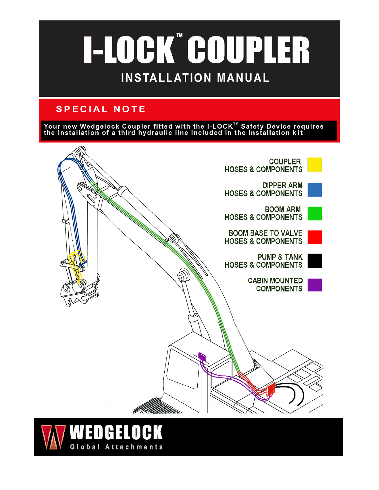
machines from 1 tonne to 100 tonne. Spearheading the range is the I-Lock™ Coupler.
Changes in law and safety standards have piloted the design and development of the I-Lock™ Coupler, a
world first in coupler safety. The I-Lock™ Coupler incorporates all the original features of a standard
Wedgelock Hydraulic Coupler but with the added I-Lock™ Safety System.
INTRODUCTION

Parts & Service 28/06/2009 902-001-2 Rev 0 5 of 28
Please take the time to read and understand the information presented to you in this operation manual to ensure
you get the full benefit and life expected of your I-Mcoupler.
WEDGELOCK EQUIPMENT LTD
NEW ZEALAND
Toll-free: 0800 424 482
Telephone: +64 4 526 3901
Fax: +64 4 526 3902
WEDGELOCK EQUIPMENT INC
USA
Toll-free: 888 418 3311
Telephone: +1 775 284 8262
Fax: +1 775 284 8269
WEDGELOCK
UNITED KINGDOM
C/- Harford Attachments Ltd
Telephone: +44 1603 403 099
Fax: +44 1603 402 399
WEDGELOCK
AUSTRALIA
C/- Equipment Component Holdings Pty Ltd
Telephone: +61 3 9768 3499
Fax: +61 3 9768 2315
REST OF WORLD
WEDGELOCK EQUIPMENT LTD
NEW ZEALAND
Toll-free: 0800 424 482
Telephone: +64 4 526 3901
Fax: +64 4 526 3902
CONTACTS

Parts & Service 28/06/2009 902-001-2 Rev 0 6 of 28
Please read this Installation Manual thoroughly before you commence installation of
the I-Lock Coupler. Deviating from these instructions may result in increased install
time and / or damage to the hydraulic kit, carrier machine or attachment.
1.0 CHECK LIST
Before you start check the following
•Check the contents of the installation kit against the Bill of Materials. Ensure that the kit supplied is
the correct one for the carrier machine that the coupler is to be installed.
•Check that the carrier machine is positioned on level ground.
•Check that you have absorbent materials available to soak up any fluid spills. Dispose of any used
materials in a safe and environment friendly manner.
•Power off the carrier machine. If the machine has been working ensure that it has cooled down
adequately prior to commencing any part of the installation procedure.
•Before carrying out any welding on the carrier machine disconnect the battery. Refer to the carrier
machine operator / maintenance manual.
•Ensure that the pressure in the hydraulic system is relieved before opening any hydraulic lines.
SECTION 1:
INSTALLATION GUIDELINES

Parts & Service 28/06/2009 902-001-2 Rev 0 7 of 28
Please ensure you follow the stated precautions below whilst carrying out the coupler and hydraulic kit
installation procedure.
2.0 SAFETY PRECAUTIONS
•Always use PPE (Personal Protective Equipment) when servicing, operating or maintaining plant,
machinery and its components.
•Refer to the carrier machine “Service Manual” for correct procedures when carrying out work on the
machine. The machine service manual takes precedence over any discrepancies between that and
this installation manual.
•Allow for hydraulic oil to cool adequately before opening or accessing any hydraulic lines. Hydraulic
lines, fittings and components can be hot which can be harmful causing severe burns.
•Relieve the hydraulic tank pressure before accessing hydraulic lines. Refer to the carrier machine
service manual for proper procedures.
•Ensure that the stick of the carrier machine is resting on the ground at all times – do not leave
attachments suspended in the air during service / installation.
•Check and tighten all fittings, hose connections and joints within the hydraulic quick coupler circuit
prior to activating the machine.
•Visually inspect for oil leaks tighten and adjust accordingly. Avoid contact with hydraulic fluids
and high pressure oils – use cardboard or similar as a backing when checking for leaks.
•Oil spills are sometimes unavoidable. Contain all fluid spills with appropriate absorbent materials and
dispose accordingly. Immediately clean affected areas to minimize safety risks.
•When operating plant and machinery keep people and property well out of harms way. Evaluate the
working environment and identify hazards. Ensure that all people involved in the installation
understand the hazards associated with this procedure.
2.1 WELDING PRECAUTIONS
•Before commencing any welding procedures on the carrier machine ensure that the engine is turned
off and the battery supply is disconnected (refer to the carrier machine service manual)
•Ensure all surrounding areas are protected with a flame resistant covering. Clear surrounding areas
of combustible materials. Ensure you have a fire extinguisher at hand.
•Cover highly susceptible surfaces like cylinder rods, glass windows, electrical components and
plastics to prevent spatter or heat damage.
•Connect the ground cable (earth lead) from the welder to the component to be welded to the carrier
machine.
•Ensure parts and surfaces to be welded are clean and prepared properly for welding.
•Use appropriate PPE (Personal Protective Equipment) when carrying out any welding procedures.
SECTION
2
:
PRECAUTIONS

Parts & Service 28/06/2009 902-001-2 Rev 0 8 of 28
3.0 SAFETY DURING COUPLER INSTALLATION
•Always use the correct PPE when removing attachments from carrier machines.
•Stand well clear of machinery that is in motion at all times.
•NEVER place hands or fingers near pin holes or recesses.
•Always use correct tools when carrying out removal and installation of attachments on the carrier
machine.
•Use correct lifting techniques and lifting equipment when maneuvering heavy objects
•Attachments may roll or tip during removal when placed on the ground – place with extreme caution
•Always use assistance when installing and removing attachments pinned to the carrier machine
3.1 COUPLER ORIENTATION
The I-Lock Coupler has been designed and manufactured to fit the dipper arm and
linkage assembly of the carrier machine. The I-Lock Coupler fits the carrier machine in
one orientation only with the C-Section facing the operators view (see fig 3.0.1)
•Always use the original bucket pins to fit the coupler the machine. These pins are designed for
the dipper arm and linkage assemblies.
•Always replace o’rings to original positions and utilize pin retention systems where applicable.
•DO NOT use standard attachment pins to connect the coupler to the machine. If unsure consult
your Wedgelock Dealer immediately.
•If a THUMB is / will be fitted to the carrier machine utilizing the main dipper pin position refer to
the THUMB Installation Guide for reference.
Correct Incorrect
FIG 3.1.1 Coupler Orientation
SECTION
3
:
COUPLER INSTALLATION
Dipper Arm
(Operator View)
Coupler C-Section
Coupler C
-
Section

Parts & Service 28/06/2009 902-001-2 Rev 0 9 of 28
3.2 REMOVING THE EXISTING BUCKET
Before you fit the coupler to the carrier machine you have to firstly
remove any existing attachment from the dipper arm. (Fig 3.2.1)
•Place the bucket or attachment in a safe position on the ground.
•Undo the pin retention systems holding the dipper pin and link
pin in their position.
•Gently raise the bucket off the ground and crowd the cylinder
until the weight is off the dipper pin.
•Remove the dipper pin and place in a clean area.
•Lower the bucket to the ground with the crowd cylinder until
there is no longer weight on the link pin.
•Remove the link pin and place in a clean area.
3.3 FITTING THE COUPLER (Link Pin)
•Ensure the coupler is sitting on a flat surface in the correct
orientation.
•Align the dipper arm of the carrier machine with the coupler.
•Position the o’rings for the linkage boss assembly on the linkage
boss (if fitted).
•Using the crowd cylinder lower the linkage into position on the
rear boss of the coupler (Fig 3.3.1)
•Align the coupler if necessary using a bar or lever.
•Insert the linkage pin through the coupler boss and linkage boss.
•Align pin retention system and fix linkage pin into place.
•Locate the o’rings into the correct position (if fitted).
•NOTE – ORIGINAL OEM LINKAGE PIN MUST BE USED.
SECTION
3
:
COUPLER INSTALLATION
Fig 3.2.1 Remove Bucket
Fig 3.3.1 Lower linkage into coupler

Parts & Service 28/06/2009 902-001-2 Rev 0 10 of 28
3.4 FITTING THE COUPLER (Dipper Pin)
•Place o’rings over ear plates of coupler to hold in position until ready for final placement.
•Carefully raise the dipper arm of the carrier machine so that the weight of the coupler is off the
ground. Ensure that the dipper arm is in a vertical position. (Fig 3.4.1).
•Retract the crowd cylinder until the coupler front boss aligns with the dipper pin hole. The coupler will
balance allowing an easy insertion of the main dipper pin (Fig 3.4.2).
•Align pin retention system and fix dipper pin into place.
•Grease both the dipper pin and the linkage pin.
•Crowd coupler through full rotation to check clearances.
•NOTE – ORIGINAL OEM DIPPER PIN MUST BE USED.
CAREFULLY CROWD THE COUPLER THROUGH FULL ROTATION TO CHECK
CLEARANCES
IF THERE ARE ANY SIGNS OF INTERFERENCE STOP IMMEDIATELY AND
CONTACT YOUR WEDGELOCK DEALER
Fig 3.4.1 Raise dipper arm to
take weight off coupler
Fig 3.4.2 Retract crowd cylinder
to align dipper pin
SECTION
3
:
COUPLER INSTALLATION

Parts & Service 28/06/2009 902-001-2 Rev 0 11 of 28
There are three main sections to the hydraulic kit installation which consists of:
1. Fitting of the Junction Manifold Block to the dipper arm.
2. Fitting of the I-Lock Control Valve in the engine compartment.
3. Routing the 3 Line Hydraulic Circuit to complete the hydraulic part of the coupler installation.
4.0 JUNCTION MANIFOLD POSITION
The Junction Manifold block is a 9 port block designed to enable
multiple routing options and variable positional options to optimize the
jumper hose routing at the base of the dipper arm. Note correct
orientation. (Fig 4.0.1)
•Positioning of the Junction Manifold Block
and the hose routing option is critical to the
life cycle of the jumper hoses. (Fig 4.0.2)
•To determine the optimum position of the Junction Manifold Block firstly rotate the crowd
cylinder through full rotation to check available clearances for the manifold at both full stroke and
zero stroke.
•The manifold should be placed as close as possible to the main dipper pin to minimize jumper
hose length – when utilizing universal jumper hose kits any excess jumper hose can be then
contained inside the coupler body.
4.1 FITTING THE JUNCTION MANIFOLD BLOCK
•Once the optimum position has been determined, clean and prepare the surface of the dipper arm to
be welded.
•Lightly tack the manifold into position, carefully tacking only the ends of the manifold. (Refer to
welding precautions and carrier machine service manual for welding instructions)
•Fit one adaptor to the manifold and rout one jumper hose from the manifold to the coupler cylinder.
•Crowd coupler SLOWLY through full rotation checking that the hose can move freely and is not
subject to pinching or crushing at any point. Re-position manifold if required.
•Remove jumper hose, stitch weld the ends ONLY of the manifold block to
the dipper arm. (Fig 4.1.1 Stitch weld location)
•Touch up paint finish on welded component to match carrier machine
colour.
SECTION
4
:
HYD
RAULIC KIT INSTALLATION
Fig 4.0.1 Junction Manifold Block
Fig 4.0.2 Hose routing options
Fig 4.1.1 Stitch weld location
Weld here on both ends
This side to dipper arm
(Correct orientation)

Parts & Service 28/06/2009 902-001-2 Rev 0 12 of 28
4.2 THE I-LOCK CONTROL VALVE
•The I-Lock Coupler is designed to operate on MAINS PRESSURE supply. The I-
LOCK CONTROL VALVE controls the oil pressure and flow to the coupler for both
the Primary Wedge function AND the Safety Knuckle function. The I-Lock Coupler
Control Valve MUST BE USED for any installation of an I-Lock Coupler.
•The I-Lock Control Valve consists of twin solenoid valves, twin pressure reducing valves and 5 ports
for hose routing. The distinguishable markings are there to assist with the electrical connection and
hose routing to ensure that the coupler operates in accordance with which it has been designed. (Fig
4.2.1)
•The markings on the control valve are follows. For service details regarding the control valve refer to
the service section in the Operators Manual.
Twin Solenoid Valves
a. SAFETY – safety knuckle solenoid.
b. WEDGE – primary wedge solenoid.
5 Ports for hose routing
a. P – pressure supply.
b. T – tank return.
c. RET – primary wedge retract.
d. EXT – primary wedge extend.
e. SAFETY – safety knuckle release.
4.3 INSTALLING THE CONTROL VALVE
•Identify the pump that delivers flow to the CROWD CYLINDER of the carrier machine. This is the
most common pump used for hydraulic couplers operating on mains pressure (refer to the carrier
machine service manual if required).
•Utilizing the mounting plate supplied determine a suitable location in the
pump / engine compartment of the carrier machine to mount the control
valve. The mounting plate can either be welded or bolted into position.
(Fig 4.3.1 Mounting Plate)
•Bolt the Control Valve to the mounting plate with the bolts provided.
NOTE: The best position for mounting of the control valve may be determined after the hose routing from
the boom to the pump compartment. Check where the hoses exit from the boom end in the pump
compartment before mounting the valve as the I-Lock hoses will invariable follow this same route.
SECTION
4
:
HYDRAULIC KIT INSTALLATI
ON
Fig 4.2.1 I-Lock Control Valve
Fig 4.3.1 Mounting Plate

Parts & Service 28/06/2009 902-001-2 Rev 0 13 of 28
4.4 HOSE ROUTING
Wedgelock Hose Kits have been designed to improve the speed and ease in which an
installer can fit the hydraulic kit. The content of the hydraulic hose kit has been pre
determined to ensure that, in most cases, the majority of fittings required to complete the
install are provided. In some circumstances additional fittings may have to be sourced to
complete the connection to the pump test port and tank return. For information regarding
the port type at these locations please refer to the carrier machine service manual.
The Wedgelock hose kits are colour coded with coloured cable ties at each end of the pre crimped hoses.
Following the Installation Reference Card will assist with identifying each of the hoses to be routed in
respect to their relative positions on the carrier machine. Once the manifold block and solenoid control
valve are in position it is advisable to begin routing the hoses from the coupler end of the machine to the
engine compartment end.
4.5 HOSE ROUTING – DIPPER ARM
•Connect the “Jumper Hoses” from the quick coupler cylinder to the junction manifold block mounted
on the dipper arm. Use jumper hoses, nylon abrasion sleeve and fittings provided which are colour
coded YELLOW. Note which hoses are connected to which ports on the quick coupler cylinder as
these will have to match the port options on the valve in the engine compartment.
•Connect the “Dipper Arm” hoses to the junction manifold block using the hoses and fittings colour
coded BLUE. Route these hoses along the upper side of the dipper arm.
•Determine best position for the hose clamps provided. Prepare surface of the dipper arm for welding
the clamps into position. Weld clamp assemblies ensuring that only the vertical ends of the clamp
brackets are welded. Touch up paint the dipper arm and clamp to match the carrier machine colour.
(Fig 4.5.1)
•During clamp welding procedure ensure that the dipper hoses are placed in a clean and safe
position away from heat and the welding area.
•Lightly clamp dipper arm hoses into position, do not fully tighten at this stage. (Fig 4.5.2)
SECTION
4
:
HYDRAULIC KIT INSTALLATION
Fig 4.5.2 Hose Clamp Assembly
Fig 4.5.1 Hose Clamp Position
(example only)
Hose Clamps

Parts & Service 28/06/2009 902-001-2 Rev 0 14 of 28
4.6 HOSE ROUTING – BOOM
•Fit the nylon abrasive sleeve over the loose ends of the Dipper hoses.
Using the GREEN colour coded hoses for the Boom, connect these to
the dipper arm hoses. (Fig 4.6.1)
•Lay the Boom hoses along the top of the boom arm in preparation for
determining the best hose clamp position for this part of the
installation. (Fig 4.6.2)
•Mark the position of the top hose clamp on the boom, allowing for the hose to follow the boom
movement relative to the dipper arm movement on the top pivot point. Following the existing hose
route and length through this pivot area is recommended.
•Mark the position of additional hose clamps along the top of the boom. Prepare the surface of the
boom for welding in these locations. Weld clamp assemblies ensuring that only the vertical ends of
the clamp brackets are welded. Paint the boom and clamp to match the carrier machine colour.
•Tighten all hose joints between the coupler cylinder and the dipper arm to boom connections.
•Tighten the clamp assemblies, pulling through any excess hose, working from the dipper end to the
bottom of the boom. Allow “hose slack” for pivot movement ensuring that the hose assemblies are
not stressed in any way. Use cable ties where required.
SECTION
4
:
HYDRAULIC KIT INSTALLATION
Fig 4.6.1 Hose Joint
(Typical)
Fig 4.6.2 Boom Hose Routing
Dipper to Boom Hose Joint
Clamp Assemblies
(Multiple locations along boom)
Boom to Valve Hose Joint
Hose slack for pivot movement
(with nylon abrasive sleeve)

Parts & Service 28/06/2009 902-001-2 Rev 0 15 of 28
4.7 HOSE ROUTING – BOOM TO VALVE
•Connect the RED colour coded hoses to the green boom hoses at the base end of the boom.
•Route the hoses through to the pump compartment towards the control valve following the existing
hose routing from the boom end.
•Trace the hoses from the quick coupler cylinder right through to the end where they connect to the
valve to determine the correct hose for each port position on the valve.
•Connect the hose ends to the control valve ensuring that they are connected to their respective port
positions relative to the cylinder.
•Cable tie Boom to Valve hoses to existing hoses where appropriate and coil any excess hose in the
pump compartment. Ensure that the hoses are not bound up or under any strain.
•Tighten all hose joints and fittings between the lower boom end and the control valve.
4.8 HOSE ROUTING – VALVE TO PUMP / TANK
•Using the BLACK colour coded hoses connect the hose ends to the valve ports marked P (Pump)
and T (Tank)
•Utilizing a “TEST PORT” on the pump that delivers hydraulic pressure to the crowd cylinder (see 4.3
above) connect the hose from the “P” port to the test port.
•Locate an existing “RETURN” hose on the main return manifold or hydraulic tank. Disconnect the
existing hose and install a tee fitting.
•Reinstall the existing hose onto one end of the tee and then connect the new return hose from the
control valve “T port to the other end of the tee.
•Cable tie hoses to existing hoses where appropriate and coil any excess hose if required. Ensure
that the hoses are not bound up or under any strain.
•Tighten all hose joints and fittings between the control valve and the pump and tank.
NOTE 1: Wedgelock has endeavoured to supply the majority of the fittings required to carry out a complete
install of an I-Lock Coupler, however due to the vast array of different carrier machines, fitting types and
port sizes, not all circumstances may be accounted for. In instances where the fittings supplied do not
match the port size or the type of carrier machine please contact your nearest machinery dealer or
hydraulic fittings provider for the additional appropriate component(s).
NOTE 2: See Hydraulic Schematic (Fig 6.0.1)
SECTION
4
:
HYDRAULIC KIT INSTALLATION

Parts & Service 28/06/2009 902-001-2 Rev 0 16 of 28
5.0 ELECTRICAL INSTALLATION
The I-Lock Coupler must be operated utlizing the I-LOCK
CONTROL SWITCH. The I-Lock control switch has been
designed in conjunction with the functionality and operation of
the coupler safety features. The built in ‘Timer” and
“Operational Sequences” controlling the solenoid valves are
features which provide the operator and fellow co-workers a
safe work environment during attachment change over. Failure to utilize the
proprietary control switch with the I-Lock Coupler could result in coupler
malfunction, causing serious harm or even death. (Fig 5.0.1)
•The Control Switch is supplied with double adhesive tape which allows for the ease of fitment to
either the window of the carrier machine or directly onto the console. The control switch also comes
complete with a “plug & play” wiring harness.
•Determine a suitable position for the Control Switch. It is recommended that the control switch is
installed so the operator can reach it with ease. Remove the backing tape and affix into position.
•Locate a switched (fused) power source from within the cab / consol of the carrier machine. Plug the
wiring harness into the flying lead on the control box.
•Route the shorter leads of the harness to the selected power source and connect the BLACK/RED
wire. Find a suitable earth location (negative) and connect the BLACK wire.
•Ensure that the wiring harness from the control switch to the power supply and earth is routed and
fixed securely with the cable ties provided.
•Route the longer leads of the harness which are coloured GREY, GREY / BLACK and WHITE,
WHITE/YELLOW to the hydraulic control valve in the pump compartment.
•Connect the GREY and GREY / BLACK leads to the “WEDGE” solenoid DIN connector.
•Connect the WHITE and WHITE/YELLOW leads to the “SAFETY” solenoid DIN connector
•Ensure that the wiring harness from the control switch to the solenoids is routed and fixed securely
with the cable ties provided.
•Polarity of connections is not critical.
NOTE: See Electrical Schematic (Fig 6.1.1)
SECTION
5
:
ELECTRICAL INSTALLATION
Fig 5.0.1 I-Lock Control Switch

Parts & Service 28/06/2009 902-001-2 Rev 0 17 of 28
6.0 HYDRAULIC SCHEMATIC
6.1 ELECTRICAL SCHEMATIC
SECTION
6
:
SCHEMATICS
Fig 6.0.1 Hydraulic Schematic
Fig 6.1.1 Electrical Schematic

Parts & Service 28/06/2009 902-001-2 Rev 0 18 of 28
7.0 FINISH & TEST
Before starting this section, position the machine in the “Oil Level Check” position as
suggested by the excavator machine manufacturer. Check the oil level sight gauge on the
hydraulic tank. Add hydraulic oil if necessary (refer to the carrier machine service manual
for further information).
•Check the hose clamp assemblies and valve mounting bolts are tightened as per the Torque Setting
of Metric Bolts & Nuts Chart (Fig 8.0.1)
•Starting at the coupler end thoroughly check that the hose connections are tightened through out the
complete circuit as per the JIC (SAE 37º FLARE) Connection Chart (Fig 8.1.1).
•Clear all personnel and all obstacles from the swing radius area and working parameter of the
machine.
•From the seat of the excavator, start the machine and lower the excavator arm to near the ground. In
a very slow motion, raise the dipper arm and crowd the coupler through full rotation. Then raise the
boom of the excavator and motion the dipper arm cylinder to full extension. Now motion the dipper
arm cylinder to full retraction, lowering the boom arm in unison. Use this process to check the hose
routing throughout the complete circuit. Ensure that the hoses are not under any strain or subject to
potential jamming or pinching. Assistance will be required to do this. Modify hose routing if required.
•Running the machine at idle or a low engine RPM setting to supply a low volume of oil through the
circuit, activate the circuit and check for leaks. Shut down the machine immediately if leaks are
detected, then tighten as required and re-check.
•Activate the circuit several times to ensure that the system is working correctly – refer to the I-Lock
Coupler Operators Manual.
•Once the test procedure has been completed, touch up paint any welded brackets or assemblies
and cable tie any loose hoses.
•Affix “In Cab” Decals in a suitable location within the
operators working area. (Fig 7.0.1 In Cab Coupler Warning, Fig 7.0.2 In
Cab I-Lock Operation)
Before using the I-Lock Coupler read the I-Lock Coupler Operators
Manual thoroughly.
SECTION
7
:
FINISH & TEST
Fig 7.0.1 “In Cab” Coupler
Warning
Fig 7.0.1 “In Cab” I-Lock Operation

Parts & Service 28/06/2009 902-001-2 Rev 0 19 of 28
8.0 TORQUE CHART – METRIC BOLTS
The following chart gives the standard torque setting of the bolts used in this hydraulic kit installation. It is
important to follow the chart when installing bolts and nuts. Failure to do so could result in premature
failure, damage to components, or even serious injury. (Fig 8.0.1)
Torque Setting of Metric Grade 8.8 Bolts & Nuts
Bolt Dia x Pitch (mm) Nm Lb.Ft
M6 x 1.0 9.9 7.3
M8 x 1.25 24.0 17.7
M10 x 1.5 48.0 35.4
M12 x 1.75 83.0 61.2
M14 x 2.0 132.0 97.3
M16 x 2.0 200.0 147.4
M18 x 2.5 275.0 202.7
M20 x 2.5 390.0 287.4
Note: 1Nm = 0.102kgm = 0.737 lb.ft
Fig 8.0.1 Torque Setting of Metric Grade 8.8 Bolts & Nuts
8.1 TORQUE CHART – JIC CONNECTIONS
JIC (SAE 37º Flare) Connections are a very common connection in fluid power applications. Both the male
and female fittings have a 37º seat. The seal takes place between the male flare and the female cone seat.
The thread holds the connection mechanically.
Torque Setting of JIC Connectors
Nominal Size Dash Size Nm Lb.Ft F.F.F.T
¼” -4 15 – 17 10.8 – 12.5 2
3/8” -6 27 – 30 19.6 – 22.0 1 ¼
½” -8 59 - 65 45.5 – 47.8 1
Fig 8.1.1 Torque Setting of JIC Connectors
SECTION
8
:
TORQUE CHARTS

Parts & Service 28/06/2009 902-001-2 Rev 0 20 of 28
9.0 HOSE KIT, I-LOCK 130
The following table lists the contents of a full universal kit to suit a 130 weight class I-Lock Coupler. The
colour codes cross reference with the Installation Reference Card at the front of this manual.
PART NO. DESCRIPTION QTY
COLOUR
CODE
131-1060-1
HOSE ASSY, 1/4 x 1060mm, 7/16JICF-7/16JICF, 900mm
HNG50 3 3
131-3200-1 HOSE ASSY, 1/4 x 3200mm, 7/16JICF-7/16JICF 3 3
131-6600-1 HOSE ASSY, 1/4 x 6600mm, 7/16JICF-7/16JICF 3 3
131-2720-1 HOSE ASSY, 1/4 x 2720mm, 7/16JICF-7/16JICF 3 3
131-2100-1 HOSE ASSY, 1/4 x 2100mm, 7/16JICF-7/16JICF 1 1
HOSES
131-1120-1 HOSE ASSY, 1/4 x 1120mm, 7/16JICF-7/16JICF 1 1
130-002-1 UNION, 7/16"JICM-7/16"JICM 6 3 3
130-003-4 ADAPTER, 7/16"UNOM-7/16"JICM 14 3 6 5
130-003-1 ADAPTER, 9/16"JICF-7/16"JICM 4 4
130-003-2 ADAPTOR 9/16 UNOM-7/16 JICM 1 1
130-003-3 ADAPTOR 13/16 ORFSF SWIVEL- 7/16 JICM 2 2
130-003-6 ADAPTER, 3/8"BSPF SWIVEL-9/16"JICM 2 2
130-003-7 ADAPTER, 3/8"JISF-9/16"JICM 2 2
130-003-8 ADAPTER, 3/8"BSPPM - 7/16 JICM 1 1
130-003-9 ADAPTER, 1/4"BSPPM -7/16 JICM 1 1
130-005-1 TEE, 3/8"JISF SWIVEL RUN, 3/8"JISM-3/8 JISM 2 2
130-005-2 TEE, 9/16"JICF SWIVEL RUN, 9/16"JICM-9/16"JICM 2 2
130-005-3 TEE, 3/8"BSPPF SWIVEL RUN, 3/8"BSPPM-3/8"BSPPM 2 2
130-005-4 TEE,13/16ORFSF SWIVEL RUN,13/16ORFSM,13/16ORFSM 1 1
130-009-1 DOWTY SEAL, 1/4 BSPP 1 1
130-009-2 DOWTY SEAL, 3/8 BSPP 1 1
130-006-1 90 ELBOW, 7/16"JICM-7/16"JICF SWIVEL 8 3 5
130-006-2 45 ELBOW, 7/16"JICM-7/16"JICF SWIVEL 3 3
130-010-1 HOSE CLAMP TWIN 1/4" 7 3 4
HYDRAULIC FITTINGS
130-010-2 HOSE CLAMP SINGLE 1/4" 7 3 4
132-050-1 NYLON SLEEVE, 50mm ID 1.5
117-000-040-3
MISC
133-300-8 CABLE TIE 300 X 8mm 20
116-012-024-1 SWITCH, ROTARY, ELECTRONIC, I-LOCK 1 1
114-103-024 VALVE, I-LOCK CONTROL, 24V 1 1
115-902-4 MANIFOLD, DIPPER, 7/16" UNO x 9 PORT, 3 PLUG 1 1
T10994-X11006 BRACKET, COUPLER CONTROL VALVE 1 1
103-080-070 BOLT & NUT, M8 x 70, ZP, 4.6 2 2
902-001-2 MANUAL, I-LOCK INSTALLATION 1 1
902-002-1 MANUAL, I-LOCK OPERATION 1 1
903-002-1 DECAL, IN CAB, COUPLER WARNING 1 1
WEDGELOCK
903-001-2 DECAL, IN CAB, I-LOCK OPERATION 1 1
SECTI
ON
9
:
INSTALL KITS
Table of contents
Other WEDGELOCK Industrial Equipment manuals
Popular Industrial Equipment manuals by other brands

ABB
ABB A255-L32 Operation manual

Titan
Titan 114 Installation, Maintenance, and Parts Manual

Manntek
Manntek DCC Service instruction

Graco
Graco President K Series Instructions-parts list

ZeroClamp
ZeroClamp NP90 Assembly and maintenance instruction

Larson Electronics
Larson Electronics IND-CDL-SQ-10-FUVC-MP-1L-V1 instruction manual

Magnaflux
Magnaflux D-2100 Series installation guide

CARBONEX
CARBONEX ECHO-PG Technical And Operating Manual

YZ Systems
YZ Systems NJEX 610G Instructions & operating manual

Jäger
Jäger Z62-H360.02 S19W2/2 manual

Cerrowire
Cerrowire ReelRover quick start guide

Porter
Porter 2400 Series Assembly & operation manual