Bungard CCD/2 User manual

CCD
Operator's manual Page 1 /35

CCD
Operator's manual Page 2 /35
Table of content
General......................................................................3
Special features:...................................................3
Mechanic:............................................................3
Spindle:................................................................3
Drive system:..................................................4
Software:.........................................................4
Technical Data..........................................................5
General.................................................................5
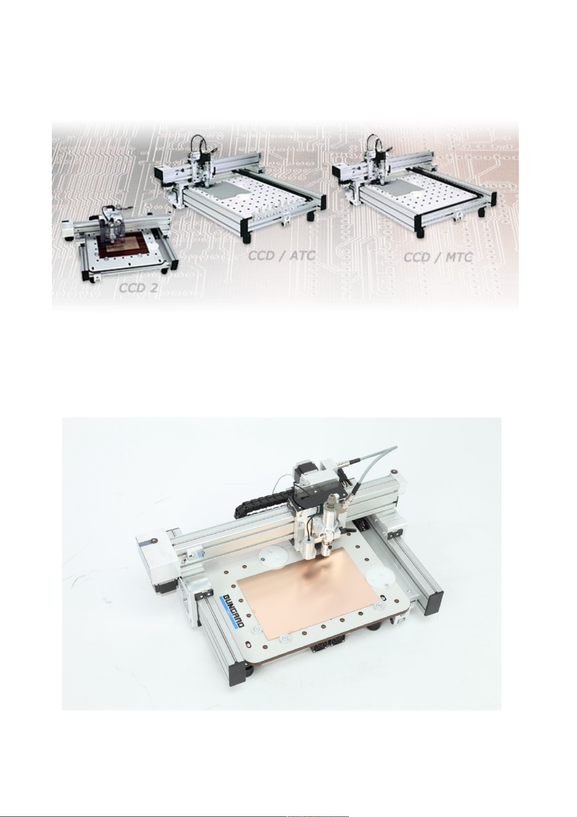
Comparison..........................................................5
pplications.........................................................5
Options.................................................................6
ccessories..........................................................6
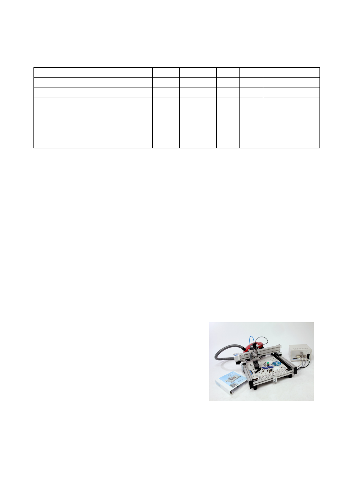
mount of delivery..............................................6
Safety instructions.....................................................7
General.................................................................7
Emergency Stop Facilities...................................7
Protection against contact with moving parts.......7
Location...............................................................7
Noise....................................................................8
Dust......................................................................8
Power supply.......................................................8
Maintenance.........................................................9
Tools....................................................................9
Documentation.....................................................9
Short Instructions/Setup..........................................10
Installation Manual RoutePro3000.........................18
Detailed Instructions...............................................20
Control unit and mechanics..........................20
Power supply................................................20
Control unit...................................................20
Mechanics Unit..................................................21
Set up.................................................................21
( TC) Compressed air connection...............21
Vacuum cleaner............................................22
Mounting the spindle....................................22
Spindle accessories.......................................23
Drill pressure foot.........................................23
Depth limiter.................................................23
( TC) Tool slots...........................................25
(MTC) Tool change......................................25
Maintenance..................................................25
Fixing the boards..........................................26
Clamp fixing.................................................26
Span fixing....................................................26
Reference pins / Isolation milling.................26
dhesive tape................................................26
Vacuum fixation...........................................26
Drilling bare boards......................................27
Pre-sensitized base material..........................27
Etched PCBs.................................................27
Routing.........................................................27
Engraving......................................................27
Drill and route parameter........................................28
Standard drill.....................................................28
Parameter......................................................28
Spade type drill..................................................29
Microvia-drill ....................................................29
Slot drill.............................................................29
Flex drill............................................................29
Isolation milling tool .......................................29
Routing parameters.......................................30
SC/FT...............................................................30
Routing parameter.........................................30
RPU ................................................................31
Routing parameter for RPU........................31
V-Cut-Router ..................................................32
Parameter:.....................................................33
3-Flute router.....................................................33
Diamond patterned router..................................33
Contour finishing router.....................................34
Guarantee................................................................34
Disclaimer of warranty...........................................34
Copyright................................................................34

CCD
Operator's manual Page 3 /35
General
The CCD is a high quality computer controlled
drilling and milling machine with semi automatic or
automatic tool change. It allows direct processing of
Excellon or Sieb&Meyer drill data or HP/GL data for
the PCB production (drilling, milling, isolation rout
ing) and milling / routing of plastics, aluminium and
other metals.
In addition, the CCD can be upgraded with an at
tachment for dispensing of solder paste or glue, a
laser imaging head for exposing photoresists and a
camera for calibration and inspection tasks.
Special features:
Mechanic:
•rigid and flat construction with low moving
weights and high quality bearings for high
speed positioning
•Machine bed with universal fixation system, suitable for clamp or span fixing or for reference pins (fi
ducials). Fixing pcbs with reference/fixing pins at no extra costs by using our standard backing
boards. As an option a vacuum table can mounted underneath the base table to allow vacuum fixa
tion of the PCB
•You can fix the PCB at the machine zero position. Devices for span fixing included, clamp fixing for
heavy duty milling possible
•Integral depth limiting device for isolation milling and engraving on uneven surfaces is part of deliv
ery, work level is roughly set by the Z stepper motor and fine adjustment is done with the micrometer
screw of the depth limiter
•Removable, spring load pressure foot for drilling of flexible and uneven PCBs
•Stack processing of several boards at once is possible (typical stack: three 1.6 mm thick boards plus
one underlay/base sheet)
•Working depth not limited by depth sensor, only by flute length of the tool (standard: 5..10 mm)
•All common PCB drills/mills with 1/8" shank, with industry standard length setting by collar can be
used
•Control unit, full set of cables
•Independent controller to connect the CCD to any standard PC via USB or serial port
Spindle:
•KaVo high precision spindle motor, 150 Watt, 63 000 RPM, with heavy duty long life bearings, includ
ing 1/8" (3.2 mm) chuck
•Software controlled spindle speed. Electronic spindle load control with software feedback. Spindle
quick start and quick stop
•Drill speed: 5 hits/s (=18000 holes per hour)
•MTC: Fast, semi automatic tool change by quarter turn of the fixing knob
•The machine is locked there, no height recalibration required
•ATC: Automatic tool change, simultaneous 16 out of 99 tools per Job

CCD
Operator's manual Page 4 /35
•ATC/XL: simultaneous 25 out of 99
tools per Job
•ATC: drill break detection and length
calibration
Drive system:
•High load 2x2 phase stepper motors on
all 3 axis for real milling applications and
correct adjustment of the cutting speed
for all tools
•Maximum position speed per axis:
9000/mm/min (=150 mm/s)
•Maximum working speed per axis:
9000/mm/min (=150 mm/s), individual
setting for every tool independent from
the positioning speed
•Step resolution: Software selectable: 1
mil, ½ mil, ¼ mil (= 6.35 Micrometer)
•Precision: +/ 1 step, typical repeatability ± 0.001 mm (± 0.04 mil)
•Position accuracy:20 ppm (0.002%) over the entire work space (9,9 µm with a work area of 495 mm)
Soft are:
•Fully integrated Windows control software for online machine control in real time, with convenient
user interface, including full tool management and plausibility checks
•RoutePro3000 for Windows XP Windows 8 64 bit, project related work flow, expandable by mod
ules (laser exposure, fiducial recognition, dispensing and much more. See at:
http://www.bungard.de/index.php?option=com_content&view=article&id=155&Itemid=191&lang=eng
lish)
•Resolution: 0,0001mm (0,1µm)
•Use of open format standards such as Excellon or Sieb & Meyer drill data and HP/GL data for milling.
These can be opened and edited with a simple text editor
•You can individually adjust position speed for X , Y and Z axis as well as the working speed (feed),
spindle speed (RPM) and depth for each tool. This results in:
•continuous use of the appropriate cutting speed over the entire RPM range, no need for 100 000
RPM spindles, no excessive wear of expensive bearings
•All machine parameters (speed, acceleration ramps, X / Y / Z dimensions / scaling, tool break detec
tion) can be individually set in the RoutePro software
•Simple Teach In Function for drill and route data (to copy an existing board)
•Smallest tool diameter: 0.1 mm (zyl. Micro cutter at 63 000 1/min)

CCD
Operator's manual Page 5 /35
Technical Data
General
Po er supply: 110 240 V, 50 60 Hz + vacuum cleaner(1500W)
Range of RPM: 30.000 – 63.000
Travelling speed: 1 – 9000 mm/min
Soft are resolution: 0,0001mm (0,1µm)
Mechanical resolution: step resolution: Software selectable: 1 mil, ½ mil, ¼ mil (= 6.35 Mi
crometer)
Tool diameter: 0.1mm – 3,145mm (recommended, bigger tool diameter possible)
Position accuracy: 20 ppm (0.002%) over the entire work space:
Maximum position speed per axis: 9000/mm/min (=150 mm/s)
Maximum orking speed per axis: 9000/mm/min (=150 mm/s), individual setting on a per tool basis,
independent from position speed
Drill speed: 5/s (= 18.000 holes/h= 300 holes/min)
Required accessories: Computer, ATC: compressed air 6 bar
Board fixation: span fixing, clamp fixing, reference pin system, stack processing
possible
Option: vacuum fixation
Comparison
CCD/2 CCD/2/ATC MTC ATC MTC/XL ATC/XL
Weight kg 30 30 35 35
Dimensions mm 700x550x300 700x550x300 700x800x300 700x800x300 950x950x300 950x950x300
Work area mm 270x325 270x325 325x495 325x495 500x600 500x600
Tool change no 16 no 16 no 25
Applications
CCD/2 CCD/2/ATC MTC ATC MTC/XL ATC/XL
Milling and drilling single- and double-
sided PCBs
√ √ √ √ √ √
Milling/drilling RF- & micro ave sub-
strates
√ √ √ √ √ √
Milling/drilling
multilayer ith up to 16 layers *
√ √ √ √ √ √
Contour routing of PCBs √ √ √ √ √ √
Milling flexible, rigid-flex PCBs ** (√) (√) (√) (√) (√) (√)
Engraving front panels/labels √ √ √ √ √ √
Machining cut outs in front panels √ √ √ √ √ √

CCD
Operator's manual Page 6 /35
CCD/2 CCD/2/ATC MTC ATC MTC/XL ATC/XL
Milling SMT soldering paste stencils √ √ √ √ √ √
Housing production √ √ √ √ √ √
Wave solder pallets √ √ √ √ √ √
Panel cutting, Re orking PCBs √ √ √ √ √ √
Test adapter drilling √ √ √ √ √ √
Inspection templates √ √ √ √ √ √
Cooling (√) √ √ √ √ √
*) we generally recommend to etch at least the inner layers of a multilayer PCB
**) For flexible materials vacuum fixation is a nice option
Options
Vacuum table, protection hood or protection rack, converter software IsoCam, fiducial recognition and calib
ration with camera, laser exposure of photo resists, aluminium work table, routers engine adapter for plastic
milling and many more.
Accessories
Measuring microscope Compressor Accessory set Drills and Routers
Drill backing boards Reference pins Cooling device PCBs with or without photoresist
Amount of delivery
mechanic unit
control unit
complete cabling
Superb and sturdy high frequency spindle with eddy current brake and load control
Integrated mechanical milling depth limiter and pressure foot
RoutePro3000 (Windows XP Windows 8 64bit) for drilling and milling
Powerful, adjustable (500. .1500 W) vacuum cleaner
start adapter for vacuum cleaner
manual
USB/serial adapter
Set of Allen Keys
ATC: Air hose

CCD
Operator's manual Page 7 /35
Safety instructions
General
The machines are determined for drilling and milling (routing) printed circuit boards and for milling
(routing) and engraving aluminium plates. A special application is dosing of pastes or liquids onto
panel shape work pieces and the laser exposure of photo resists and solder mask. Any other type
of application is permissive only with our consent.
The machines are not determined to be connected or combined with other machines. However,
they need to be connected to and be controlled by a compatible computer. The driver software is
supplied with the machines and is relevant for security.
The machines may only be operated by qualified operators. Children and animals must be kept
off!
The machine is manufactured using tested components according to standard guide lines for elec
trical safety. This does not relieve the user his duty of care when dealing with electrically powered
devices.
Before performing any maintenance switch off the machine and unplug it.
Emergency Stop Facilities
The ESCape button on the computer stops the spindle and the stepper motors. This is indicated
by a red message/icon on the computer screen. The main switch on the control unit or power sup
ply unit cuts the machine from mains supply, but is not suitable for emergency stop: It does not al
low programmed spindle lift and quick stop.
If the computer has stopped responding and thus the EMERGENCY STOP button does not work,
you can stop the machine using the main switch of the control unit. In this case wait until the
spindle has come to a standstill.
Protection against contact ith moving parts
There is a round metal tube with a spring included with the spindle. This drill pressure foot shall be
mounted to the spindle shaft to prevent incidental contact to the moving tool. Same function has
the depth limiter when routing. The use of depth limiter and pressure foot is obligatory in the sense
of the machinery directive and the general safety standards to ensure maximum work safety.
It is not possible to entirely envelop the tool, as this would make the drilling and tool change ac
tions impossible. In case this pressure foot was not placed correctly, the following danger re
mains:
WARNING: Do not touch the tool when the spindle is operational. Prior to any tool change action,
wait until the spindle has come to a complete stop.
Under normal operating conditions and with the given work piece materials, there is no special
danger from parts being propelled off the machine. However, special operating conditions or
heavy work pieces may require that the machine is encapsulated. A protection cover is available
as an option.
Location
Put the machine onto a stable, even table and adjust the machine's 4 feet by turning them. A
stable desk and a proper setting are important to prevent vibrations etc. Make sure you have
enough room around the machine for tool change, mounting PCBs and maintenance work.

CCD
Operator's manual Page 8 /35
The machine may only be operated under normal temperature and humidity conditions, especially
only in absence of corrosive or inflammable vapours. At temperatures lower than 10 °C or higher
than 30 °C, there may occur the following problems: The spindle might not start running at low
temperatures. The stepping motors might run hot or step losses may occur at more than 30 °C in
the surrounding air.
In order to ensure a sufficient cooling, the equipment feet may not be removed, otherwise not
enough air will pass through the controller – Overheating and destruction of the end phase may be
the result.
The controller is designed to run at normal ambient temperatures (25°C) and should be operated
in an open set up with dry, dust and aggressive steam free environment.
If the controller is used within a closed cabinet or room temperatures higher than 25°C, you have
to supply additional measures for ventilation.
Increased dust load must be prevented by suitable measures.
Operation in an aggressive, dusty, humid, extremely hot or hazardous environment is at the
user's o n risk and responsibility.
The user has to care for appropriate precautions and protective devices, Any liability for damages
arising in such an environment by the operation, are hereby expressly excluded.
Noise
With the HF spindle running at full speed and the vacuum cleaner on, the noise pressure level at
1 m distance is 86 dB(A). Operators have to wear ear protection.
Dust
It is necessary that the standard vacuum cleaner is always being used during operation on printed
circuit boards. The vacuum cleaner must be OFF during and after use of alcohol or other inflam
mable or explosive liquids (i. e. used for cooling when milling aluminium). Individual operating con
ditions may require that an extraction unit with higher rating or the optional protective enclosure be
installed.
Po er supply
The machine power supply has a wide range AC input. You can run it on any common single
phase mains supply. If the power cord supplied with the machine is not suitable for your country,
please replace it. In this case it is urgently required that you ensure correct grounding to PE.
Attention! You must disconnect the machine from the main supply and wait until DC voltages
are low prior to opening the control unit or to pulling cards off from it. We deny any liability if al
terations to any mechanical, electric or electronic components of the machine are made. Prior to
any manipulation to the control unit, check that the machine has been disconnected from the
main supply.
Please make sure to fix the cable connection with screws. Do not pull the cables while the ma
chine is under power. First switch off controller and wait for potential equalisation.
On the rear of all machines, there is one socket for a 3.5 mm audio plug, to be used with the va
cuum cleaner switch box (pict.6). This adaptor will turn the vacuum cleaner on and off together
with the spindle. It comes in a black plastic housing with AC inlet and outlet for European mains
sockets and should be used with the vacuum cleaner that we supply, or i. e. with a liquid cooling
pump for aluminium routing. If you connect other devices, power rating must not exceed 1500
Watt.

CCD
Operator's manual Page 9 /35
For the connection of safety switches (e.g. hood switches) a shielded cable should be used, it
must be kept as short as possible. This cable just like all remaining connection/feeder cables
between Controller and CCD should not be laid parallel to power cables in order to prevent in
ductive or capacitive linking of high energy transients and thus possible over voltage damage in
the CONTROLLER.
Not avoidable crossings with power cables must be right angle implemented to keep couple strain
as short as possible.
If in the proximity of the machines high inductive loads are operated like e.g. strong electric mo
tors, exhaust fans, contactors etc., the employment of an opto coupler can be necessary for the
connection of the hood contact/safety switch.
All damages due to over voltage, overheating, humidity, dust, corrosion or inappropriate connec
tion of external or electronic devices are excluded of the guarantee. These repairs will be
charged.
Maintenance
It is important that you regularly remove all dust and shavings from the machine. To clean and lub
ricate the steel shafts, especially those below the aluminium extrusions on the X axis, use a cloth
and some acid free machine oil. On each end of the linear bearing housings, there are lubricating
felt stripes. Regularly apply some oil to them.
The shafts on the Z axis do not need special lubrication but must also be kept clean.
Note: The machine must not be used in corrosive or inflammable atmospheres. If it will not be
used for a longer period or prior to transporting it, all steel shafts should be well lubricated.
The drive belts must also be kept clean from dust and shavings but must not not be lubricated.
The belts are subject to wear. If they show damages like lateral fray out or deformed teeth they
should be replaced.
Tools
Only tools ith ring (collar) should be used. The distance flange determines the spindle el-
evation over the table. The distance from the top edge of the ring to the tool tip is 21 mm. It
is mounted to the spindle at the factory in a way that a drill (with ring is 0.5 mm over the machine
table when the Z axis is completely down. You should not change this setting. Otherwise the
mechanical position of the Z axis will be different from the one assumed by the driver software.
Damage to the machine table may then result.
Documentation
Our distributor / reseller in your country is encouraged and in charge of translating the German
and / or English manual coming with the machine into your native language. A declaration of EU
conformity is appending.

CCD
Operator's manual Page 10 /35
Short Instructions/Setup
You need:
•if possible a second person to lift the ma
chine off the box
•a small screw driver to secure the cables
•a multiple socket
•a drill backing board
•adhesive tape
•PCB material
•tolls (drills/routers)
Examine the packaging for transport damage.
Open the lid of the packaging, remove anchoring straps
and, with the help of a second person, lift the machine out
of the box and set it to its destination. The ground should
be level and stable. Align the 4 levelling feet so that the
machine does not wobble. Examine the machine for pos
sible transport damages.
Manual test: With no cable connected, check manually
whether all three axis move freely. Check if the supplied
spindle easily rotates.
Setup: Install the supplied Spindle. With the manual
spindle (4010) connect power cable to machine.
With the ATC (4054) also connect air supply to the socket
of the Y axis. The spindle is factory set in a way so that a
drill or milling tool with the correct length (21 mm from the
tool tip to top of the ring; 38mm total length) can be
lowered to a maximum of 0.5 mm above the table. Thus
touching the table with the tools is not possible.
Connect the supplied vacuum cleaner. The suction tube is connected to
the suction nozzle underneath the Y Axis (CCD/2: X Axis) See picture
below). Included in the delivery is a start adapter. Put this start adapter
into the multiple socket and plug the the power supply of the vacuum
cleaner into this adapter. The small cable with the cinch plug is inserted
into the motor connection box of the CCD (CCD/2: the socket is in the
back of the control box underneath the machine table. If you run the va
cuum cleaner with this adapter, the cleaner only starts, when the spindle
is turning.

CCD
Operator's manual Page 11 /35
MTC, ATC: Connect the 25 pin and two 15
pin cable from the controller to the terminals
on the back of the machine. Ensure proper
connection and tighten the screws! The
cables are not interchangeable. Do the
same with on the control unit side. After that
connect the RS232 to the PC (possibly via
the USB / serial adapter). At last plug in the
power supply.
ATC: connect machine to compressed air
supply (6 8 bar, oil free; not included in de
liver)
CCD/2: the control unit is underneath the machine. At
the front there a two fans the socket for the RS232 plug
and the diodes for power and the end switches XYZ.
At the back there are the connectors for the vacuum
cleaner start adapter and the power supply. Connect
the machine
with the
RS232 cable to
the computer (if
needed via
USB/serial con
verter). After
that connect
the machine with the vacuum cleaner start adapter and
the external power supply.

CCD
Operator's manual Page 12 /35
In the picture on the right you can see an axis and
zero point overview. All CCD machines are set up,
so that the motor connection box with the cables is
located on the left and the stepper motor of the Y
axis facing the front. On the right there are the tool
slots (ATC machines). If you stand in front of the
machine that way, then the machine zero is on the
front left, the X-axis is on the table level between
motor connection box and tool slots, the Y-axis is
the upper cross traverses and the Z-axis with the
spindle sits on the traverse and moves vertically.
The only exception is the CCD/2: this machine is set
up in a way that the RS232 port and control diodes
are pointing forward. Again, the zero point is at the
front left, but the Y-axis is in the table level of the
table and the X axis is the cross-traverses over the
table and on this X axis hangs the Z-axis with the
spindle.
USB/Serial adapter: If you want to operate the CCD via a free USB
port on your computer, then you first put the USB / serial adapter into
the free USB socket. Normally a routine for detecting new hardware in
cluding driver installation will start.
Insert at this point the small CD that came with the adapter and follow
the instructions on the screen. This installation is in two stages, which
look very similar. First a USB device is installed, secondly a virtual
COM port. So you will be prompted twice to install a driver. Do not stop
the process after the first time. Even if you later plug in the same adapter into a different USB
port, you possibly are again prompted to install the driver.
With Windows 7, it may be necessary to install the driver via the device manager.
RoutePro3000: Now insert the enclosed CD into your
computer drive and start SetupRoutePro3000.exe.
Depending on the system the modules Windo s
Frame ork 4 and Visual C++ must be installed on
your system. In general this happens automatically.
For this and for the registration of the software an in
ternet connection is required. For the start we can
skip the registration procedure by clicking continue
ithout registration. Please refer to the installation
guide and the RoutePro3000 online help for details.

CCD
Operator's manual Page 13 /35
After successful installation your screen
should look like this:
Please check the settings of the machine by
clicking on the Options tab and then on ma-
chine. You will see a picture of a CCD. If you
hover the mouse over the different functional
areas of the machine, you will notice a colour
change. Click on the areas to open the function
dialogue. If you drive over the table, you can ac
cess the table settings for example.
In each function dialogue there is a small tooth
wheel. Click on this tooth wheel and you can either
load a different machine configuration (be careful!
Your machine only works correctly with the correct
machine configuration!) or access the advanced
features, such as correction factors.
Please compare the values in the machine
configuration of the software to the docu
mentation provided with the machine.

CCD
Operator's manual Page 14 /35
Close the machine configuration and go to
the tab Manual Operation.
Check the function of the axis by clicking on
the arrow buttons. When you first click on
one arrow, the machine will perform a refer
ence drive. Make sure that the control di
odes light up when reaching the 0 position.
You can also check the function of spindle
as well as camera, dispenser or laser, if
there.
ATC: Check the function of the tool
changer. Go to tab General and click
on Open to load the project file
ccd_PCB_ 14tools. (XL Version: 25
Tools). This project file is located after
a normal installation at
C:\Users\Public\Documents\ccdpro
jects\pcb.
Go to tab Run CNC and click on
the triangle START. The next
dialogue asks you to place the
tool to the corresponding tool
slots. Make sure that the tools
have a length of 38 mm and the
distance between the top of the
ring to the tool tip is 21 mm. Fur
thermore, a test tool must be in
the spindle and the tool slot 0
must be empty. Check the cor
rect fitting of the tools in the
slots. Since there are tolerances
in the ring diameters, it can be
necessary to adjust the slots.
You can easily widen them with
a screwdriver and tighten them
by pressing from outside against
the lamellae.
Press OK. The machine now
moves to the tool sensor, checks the test tool and places it in slot number 0. Then the spindle moves
back to the sensor to check whether the tool was correctly dropped. After that it continues to slot
number 1 to load the first tool. The length of tool 1 is checked at the sensor, the spindle starts and a
positioning and drilling movement is performed. After that the machine checks if the tool is not
broken and sets the tool again in slot 1. This cycle is repeated until all 14 (XL 25 ) tools are checked.
Please be prepared to either press the ESCAPE key ( = emergency stop ) on your keyboard or click
on the red X in the top left in the RoutePro3000 window to directly stop the machine in case the tools
were not picked properly or a collision is about to happen. This may happen in case of a transport

CCD
Operator's manual Page 15 /35
damage or if you drive the machine with incorrect parameters.
Make sure that the LEDs of the limit switches and the tool sensor go on and off again when the ma
chine reaches the corresponding positions.
After the last tool, the spindle picks again the test tool and moves to the machine zero point.
All CCDs: Make a first drill and routing at
tempt!
To do so load the project file
ccd_PCB_quickstart.xml. You will find this
file on your C drive at: C:\Users\Public\Doc
uments\ccdprojects\pcb. This is a single sided board with 3 different drills, a simple isolation and
a cut out routing.
Fix a standard drill backing board using the
provided clamps on the machine table. Now fix a
PCB with at least 160 x 100 mm dimension
about 5 mm off the machine zero point (in this
project the offset for X and Y is set to 10 mm,
we recommend first to use this setting when you
create a new project. Always compare the thick
ness of your backing board and your PCB with
the values shown in the software !!!l!)
To to tab Run CNC.....

CCD
Operator's manual Page 16 /35
….... and click Start. The machine will perform a reference
run. Make sure that all 3 end switch diodes light up. With an
ATC machine the software will ask for test tool in the spindle
and whether the tools are correctly positioned in the ATC bar.
Again take care that slot 0 is free!
With a manual machine, you are asked to insert the current
tool into the spindle.
After clicking OK, the drilling begins. This is fully automatic with an ATC. For manual machines,
the first tool is processed, then the machine moves up into the Z limit switch and you will be
prompted to insert the next tool.
When the drill layer is
finished change to the
routing layer
With click on Start the machine again makes a reference
run and the processing is carried out in the same manner as
with drilling.
If you do not use a depth limiter and a discoupled spindle,
but get the milling height from the software, you can com
pensate tolerances in backing board and PCB by clicking
PgUp and PgDn. After the next vector the machine will con
tinue routing with the changed height.
The change you made is displayed on the upper right (cur-
rent tool values ) at depth.

CCD
Operator's manual Page 17 /35
We generally recommend to use a depth limiter for
isolation milling to compensate the tolerances of
table, backing board and PCB.
Caution: If the depth limiter is operated together
with an automatic tool changer, then the opening
of the green slider must point towards the tool
slots, otherwise tool or tool slot will be damaged!
If you use the depth limiter, the spindle of the Z
axis needs to be decoupled. To do so remove a
little screw from the Z axis clutch using the sup
plied Allan key and deposit the screw temporarily
in the threaded hole as shown in the picture.
The depth limter is mounted from below to the
spindle and locked with the black screw. To
change the tools, we recommend to quickly take
off the depth limiter. The green slider is a consum
able item and can be exchanged if necessary.
The head is set with a fine thread with 500μm pitch
and secured with a lock nut. On the lower part 10
adjustment points are located at regular intervals,
so if you turn the fine thread from one adjustment
point to the next, you change the milling depth 50
microns.
To set the depth, first adjust the milling depth
roughly by eye sight. Then select an uncritical
milling line, at best outside of the actual design or
a board cur line and make a test. If the track is too
deep, turn the depth limiter a little lower. If the
track is not deep enough, turn the depth limiter a
little higher. Repeat this procedure till you are con
tent with the result. Then process the complete
tool. These procedure may seem a little complic
ated, but in reality it takes about one minute and
will give perfect results!
Your machine is now set up, controlled and you have already processed two projects with your
machine. This introduction ends at this point. Further details and answer to special questions you
can find in the detailed instructions below and the RoutePro3000 help files.

CCD
Operator's manual Page 18 /35
Installation Manual RoutePro3000
System requirements:
CCD with Controller 2006 or younger.
Computer with Windows XP SP3 till Windows 8 64 bit. 900 MHz Processor, 500MB main memory
and 100 MB free disc space.
Internet connection during setup and registration. The internet connection is necessary to install
updates like Visual C++ and Framework 4. In addition you need to register your RoutePro3000
version and, if there, activate licenses for special modules (laser, dispense, calibrate etc.).
After installation you can of course work offline.
Content:
Ne machines: all necessary files including the specific parameters for your machine are packed
into the file “SetupRoutePro3000.exe”, which is located on the delivered CD. If you want to read
the help file prior to installation, you can download the help file from our homepage.
Existing machines ith RoutePro2008: You can download the
current Routepro3000 version with all necessary files including
our standard parameters for machine and tools from the customer
area of our homepage. Please register on our homepage with
your customer ID. If you are not a direct customer, please register
with the name of your dealer and the customer number you have
with him). After installation you have to adapt the parameters for
your machine from RoutePro2008 into RoutePro3000 (correction
factors, table size, values for sensor and tool slots). If you want to
read the help file prior to installation, you can download the help
file from our homepage.
Existing machines ith RoutePro3000: We created a separate
file “UpdateRoutePro3000.exe”. This file does not contain the re
source data and thus your already existing parameters for ma
chine and tools will not be overwritten. This Update version can
also be downloaded from our homepage.
Make sure your resource data are in the correct location.
(standard: C:\Program Files\RoutePro3000\Resources)
Procedure:
Read the manual of RoutePro3000. Connect CCD to your com
puter. Then install RoutePro3000: Double click on “SetupRoute
Pro3000.exe” and follow the routine. Depending on your system
Microsoft Framework 4 and Microsoft Visual C++ will be installed
automatically. If you do not have the latest firmware on your CCD
controller, then your controller will be flashed automatically. A re
start of RoutePro3000 may be required in this case.
If you use special modules like laser, calibration or dispensing, then please read the special in
struction for these modules coming with the hardware and refer to the applying help topics in the
RoutePro manual/help system.

CCD
Operator's manual Page 19 /35
The standard RoutePro3000 is for free, but after a trial time of 14 days, you need to register. The
registration process is described in the help file.
All special modules can also be tested for 14 days.
After that a license has to be acquired. Please note
that special hardware needs to be obtained for the
modules (laser head, camera, etc.). To apply for a li
cense or to register the standard RoutePro, you need
to have a Computer with internet connection.
If you have a new machine the CD coming with the
machine is already adapted to your specific machine.
No further action beyond registration and activating li
censes need to be done.
If you update from RoutePro2008 to Route
Pro3000, you need to establish the correct para
meters for your machine. Process like this: Start
RoutePro3000 and go to options and machine.
Hoover over the CCD picture and insert correct
parameters for XYZ motors, spindle, tool slots,
sensor and table. You can copy the values from
your RoutePro.ini file of your older Software
RoutePro2008.
Note: there is one exception concerning the Z pos
ition of the tool slots. In RoutePro2008 the z posi
tion of the tool slots was 0.5 – 1 mm less than z
max. E.g. if z max was 37.65, then z position of
the tool slots was approx. 37.00mm. In Route
Pro3000 the table is the 0 Position of the z axis
and you almost put the tool to 0. So now you
have to insert 0.5 – 1.0 mm in the ATC tool po
sition table.
Now your Software RoutePro3000 is ready to
use.
Have fun with your CCD and the new software Routero3000!

CCD
Operator's manual Page 20 /35
Detailed Instructions
Control unit and mechanics
Po er supply
The machine power supply has a wide range AC input. You can run it on any common single
phase mains supply. If the power cord supplied with the machine is not suitable for your country,
please replace it. In this case it is urgently required that you ensure correct grounding to PE.
Attention! You must disconnect the machine from the main supply and wait until DC voltages are
low prior to opening the control unit or to pulling cards off from it. We deny any liability if alterations
to any mechanical, electric or electronic components of the machine are made. Prior to any manip
ulation to the control unit, check that the machine has been disconnected from the main supply.
Control unit
MTC, ATC: There is a stand alone control unit with 3 cable connections to the mechanics unit.
There are one cable with 25 pin Sub D connectors and two cables with 15 pole Sub D connectors.
The connections are unique and cannot be interchanged.
CCD/2: The control unit is located underneath the mechanics unit, but the power supply comes as
a stand alone box and connects to the machine back by one cable.
Pic. 1: ATC Controller
Pic. 2: CCD/2 Power supply till
2013
From 2013 industrial power supply
Pic. 3: CCD/2 control unit (back view)
4: CCD/2 control unit (front view)
Other manuals for CCD/2
1
This manual suits for next models
5
Table of contents
Other Bungard Industrial Equipment manuals

Bungard
Bungard DL 500 User manual

Bungard
Bungard SMT3000 ECO LIGHT Plus User manual

Bungard
Bungard StenPrint 3000 User manual

Bungard
Bungard RDC 30 User manual

Bungard
Bungard Jet 34d User manual

Bungard
Bungard RDC 21-K User manual

Bungard
Bungard CCD/2 User manual

Bungard
Bungard Splash User manual

Bungard
Bungard EXP3040LED User manual
Popular Industrial Equipment manuals by other brands

Flexco
Flexco Clipper Pro 200 Operation manual

Sealey
Sealey SB990 instructions

schmersal
schmersal AZM300Z-I2-ST-1P2P-A Instructions for operation

John Crane
John Crane 4610 Installation, operation & maintenance instructions

Festo
Festo DSNU-8 instructions

CITO
CITO THAW AI-CT-D-12-F Digital Instruction Manual