Somat SPC-75S Installation and operating instructions

Operation/Service Manual
SPC-75s Close Coupled Pulping System
165 Independence Ct, Lancaster Pa 17601 (Ph:800-237-6628) (Fax:717-291-0878)

To better serve your needs in the future, please record your equipments information
below.
Model Number: SPC-75
Serial Number:
Service Company:
Service Phone Number:
Rep/ Dealer:
Rep/Dealer Phone Number:
Somat Service Dept: 800-237-6628 x 176
Somat Parts Dept: 800-237-6628 x 133
To expedite service or parts, please have the above information available before you call.
The serial number of your machine is located inside of the main electrical control panel
for your Somat equipment.

SOMAT COMPANY
LIMITED WARRANTY
SOMAT COMPANY warrants each new product manufactured by it to be free from defects in
material and workmanship under normal use and service, which does not include normal wear
of parts, ("normal use and service", with respect to Pulpers, Presses, water Hydra-Extractors,
Waste Handling and Processing Systems, shall mean the handling only of waste items of the
types listed in the SOMAT®Quotation or Sales Order therefore and within the LIMITATIONS
THEREIN set forth), its obligation under this warranty being limited to repairing or replacing any
part or parts thereof, free of charge INCLUSIVE of labor to remove and replace, f.o.b. factory from
which shipped, which shall, within one year from initial start-up of the SOMAT®System or from
date of original installation of the product if not a system be returned to SOMAT®at the factory
from which shipped, with transportation charges prepaid, and which SOMAT's examination shall
disclose to its satisfaction to have been thus defective. This warranty shall not apply to any
product or part which shall have been repaired or altered by any person not employed or
retained by SOMAT®, so as in the judgment of SOMAT®to affect its operation and reliability, nor
which has been installed, operated, or maintained contrary to SOMAT®OPERATION or
PREVENTIVE MAINTENANCE INSTRUCTION MANUALS or to other written instructions or
drawings approved by SOMAT®, nor which has been subject to misuse, negligence, or accident.
This warranty shall not apply should the SOMAT®System be initially started up without a duly
authorized SOMAT®representative present.
EXCEPT AS HEREIN EXPRESSLY STATED, NO WARRANTY, EXPRESS, IMPLIED OR BY LAW,
(INCLUDING BUT NOT LIMITED TO ANY IMPLIED WARRANTY OF MERCHANTABILITY OR
FITNESS FOR A PARTICULAR PURPOSE), IS MADE BY SOMAT; AND IN ANY EVENT SOMAT’S
LIABILITY, WHETHER IN CONTRACT, TORT, STRICT LIABILITY, OR UNDER ANY WARRANTY, OR
OTHERWISE, SHALL NOT EXCEED THE PURCHASE PRICE RECEIVED BY IT AND SHALL IN NO
EVENT INCLUDE ANY CONSEQUENTIAL, INCIDENTAL, PUNITIVE OR OTHER SPECIAL
DAMAGES.
NO CHANGE IN THIS WARRANTY AND LIMITATION OF LIABILITY AND NO SUBSTITUTE
THEREFORE (WHETHER INCORPORATED IN A PURCHASE ORDER OR OTHERWISE) SHALL BE
EFFECTIVE UNLESS SPECIFICALLY SET FORTH IN A WRITTEN INSTRUMENT SIGNED BY AN
OFFICER OF SOMAT®.
Rev. 02/10

Table of Contents:
SPC-75S, SPC-75UDT
Introduction……………………………………………………………………………..
Safety Instructions
General Description & Definitions
Installation………………………………………………………………………………..
Unpacking
Mechanical Installation
Plumbing Installation
Electrical Installation
Start-up……………………………………………………………………………………..
Forms & Lists
Warranty Validation
Operation…………………………………………………………………………………
Cleaning & Maintenance……………………………………………….
Cleaning
Maintenance
Troubleshooting
Replacement Parts………………………………………………………….
Pulper
Extractor
Electrical Panel
Safety Precautions and Warnings
READ THE MANUAL
COMPLETELY BEFORE ATTEMPTING TO OPERATE THE UNIT.
HIGH VOLTAGE!
DO NOT PERFORM ANY REPAIRS TO MOTORS OR CONTROL SYSTEMS
WITHOUT TURNING OFF THE MAIN POWER.
ALWAYS
TURN THE MAIN POWER OFF
AND LET ALL MOTORS COME TO A STANDSTILL
BEFORE DOING ANY MAINTENANCE ADJUSTMENTS OR CLEANING OF THE UNIT.
BEFORE STARTING, BE SURE
ALL PERSONNEL ARE CLEAR
OF MOVING PARTS.
KNOW LOCATION AND FUNCTIONS OF ALL
START/STOP BUTTONS
AND SAFETY
SWITCHES.
DURING PERIODIC MAINTENANCE,
CHECK ALL SAFETY SWITCHES
TO BE SURE THEY
ARE OPERATING PROPERLY.
DO NOT REMOVE
OR ALTER GUARDS.
DO NOT REMOVE
SAFETY LABELS. IF LABELS ARE MISSING OR DESTROYED, CONTACT
FACTORY FOR REPLACEMENT.
DO NOT OBSTRUCT
ELECTRICAL PANELS OR PUSH BUTTONS.
GOOD HOUSEKEEPING
IS THE MOST IMPORTANT SAFETY PROCEDURE.

Safety Precautions and Warnings
This equipment has locations which are hazardous and cause severe injury or death if
warnings are not followed. Always turn off power before reaching into any unit!
Maintenance to be performed by trained and authorized personnel.
This equipment has moving parts operating at
high speeds! Death or serious injury can occur
if warnings are not followed.
This equipment has moveable lids
protecting you from moving parts. Do not
alter safety devices or guards. Do not reach
into any part of the unit with the power
turned on.
This equipment uses High Voltage! Only
trained and authorized personnel should
perform maintenance on the electrical
components of this machine.
This equipment has moving parts that can
crush and cut. Do not alter safety devices or
guards. Do not reach into any part of the
unit with the power turned on.

Caution: Damage will occur to this equipment if unsafe objects are fed into the
machine(s). Keep these items out of the machine(s) to avoid component failure and
unwanted downtime. When in doubt, keep it out of the machine(s)!
Glass, Bottles, Jars
Cans Silverware
Metal of any kind !
China Pans Wood
Towels / Rags Scrub-Pads
Always turn the power off before servicing the pulper!

GENERAL DESCRIPTION
The SOMAT® system prepares solid waste materials for disposal by transforming the materials, with water,
into a pulp. This transformation takes place in a unit called a Pulper which is designed to pulp all forms of
paper, plastic, foil, and food waste. The waste material is fed manually or automatically to the Pulper. The
continual down flow of water and the rotation of the Pulper impeller create a strong vortex action which pulls
the waste down against the cutting blades of the impeller. The resultant slurry is then forced through a
perforated stainless steel Sizing Ring surrounding the impeller.
Items such as tin cans, silverware, nails, bolts and other non-palpable objects which may be inadvertently fed
into the Pulper are separated out of centrifugal force and gravity and are caught in the junk box within the
Pulper. This junk box should be emptied manually during cleanup.

TYPICAL PULPER
The SOMAT® System is
designed to pump the mixture of
macerated solids and water,
called slurry, to the Hydra-
Extractor® where the slurry is
reduced to a semi-dry pump.
Within the Hydra-Extractor®, the
slurry is carried by a helicoid
screw within a perforated tubular
screen. The water passes
through the screen and is
pumped back to the pulping unit.
The solids continue up the
helicoid screw to a compression
chamber or plug area where
additional water is removed by
extrusion. The solids in this area
are called the plug. This plug is
broken up at the Hydra-
Extractor® discharge opening by
a cutter and the pulp then falls
out of the discharge chute. TYPICAL HYDRA-EXTRACTOR®
This system is capable of reducing the volume of average non-compacted waste by approximately 80
percent.
The system is powered by electric motors with the associated controls housed in Som-A-Trols (electric
control panels). Since, in the course of operation, some water is absorbed by the pulp, fresh make-up
water is supplied to the Pulper automatically through a solenoid valve which responds to a water level
sensor.
In addition to the basic system as discussed to this point, numerous additional items of equipment may or
may not be required to comprise a specific system.

DEFINITIONS – GENERAL
1. Pulper - SOMATdevice that contains an impeller and security ring to grind solid waste. The
resultant mixture of waste particles and water is called slurry.
2. Hydra-Extractor- Inclined screw-type press for removing transport water from pulp.
3. Slurry - A water solution containing a low percentage of suspended solids.
4. Pulp - Semi-dry solid from which transport water has been extracted.
5. Som-A-Trol- Electrical control panel, including motor starters and sequencing controls
for automatic operation of the SOMATsystem.
6. Slurry Pump - Specially designed pump used to transport slurry from a SOMAT
Pulper to Hydra-Extractor.
7. Return Pump - Specially designed pump used to return water from Hydra-Extractorto SOMAT
Pulpers.
8. Water Level Control - a PLC controlled function utilizing time based programming.
9. Chemical Additive Pump - A proportioning type Additive pump that adds de-foaming, deodorizer,
and/or buffering solutions to the process water.
* 10. Pulp Screw Conveyor - Transport screw used for conveying pulp to a point remote
from Hydra-Extractor.
* 11. Distributing Type Pulp Screw Conveyor - Transport screw with discharge ports throughout its
length for even distribution in large haul-away containers.
* 12. Water economizing tank-Reservoir for return water used in large systems.
* Optional equipment which may not be furnished with your Pulping System.
DEFINITIONS – COMPONENTS
SOMATPULPER:
1. Tank - Pulping or grinding chamber of the SOMATPulper.
2. Impeller - Rotating metal plate with Cutting Blades and Tungsten Carbide teeth which de-fiber
and pulp the waste and along with the Security Ring provides a shearing action for non-fibrous
waste.
3. Security Ring - Perforated stainless steel ring surrounding the impeller through which all slurry
must pass after waste is pulped. Dimensions of security ring holes controls particle size of
materials leaving the Pulper.
4. Junk Box - Chamber in bottom of tank that segregates non-pulpable materials from tank.

HYDRA-EXTRACTOR:
1. Screw - Vertical helix which lifts and compresses solids from the slurry and permits water to
drain off by gravity.
2. Screen - Mesh screen that surrounds the screw, through which water drains off.
3. Plug - Mass of pulp extending beyond last helix of the screw. The force required to extrude the
plug squeezes additional water from pulp.
4. Brush - Nylon brush attached to edge of screw helix which serves to clean the screen.
5. Plug Cutter – Assists in breaking apart waste to discharge down the chute
GENERAL:
1. Throttling Valve - Full ported gate valve used to control water flow.
2. Timer - Electrical device used to automatically shut down the SOMATSystem at a pre-
determined time.
3. Fresh Water Solenoid - Electric valve used to control fresh water make-up to the SOMAT
System.
4. Motor Operated Valve - (MOV) Electric valve used to control return water flow in the system.
5. PLC- Computer controller designed to handle pulper and extractor operation.

Installation

UNPACKING
The crate containing your SOMAT®Pulper will contain the following items:
Pulper
Tray, if so equipped
Som-A-Trol®Panel
Misc. parts box containing:
ALL UNITS:
Anti-Vibration Pads
Installation Drawings
UDT UNITS ONLY:
Stainless Steel Lid
Stainless Steel Cone Adapter (Unless shipped directly to table manufacturer).
UDT Gasket
TRAY ONLY:
Gasket & Hardware
Return Water Assembly
TROUGH ONLY:
Trough Gasket & Hardware
Trough Nozzles & Throttling Gate Valves
(See Installation Drawing for quantity)
OPTIONAL EQUIPMENT:
Remote Push Button Station
Trough Magnet & Hardware
Feed hood
MECHANICAL INSTALLATION
HIGH TANK MODELS:
1) Put the pulper/extractor into position as shown on the Installation Drawings.
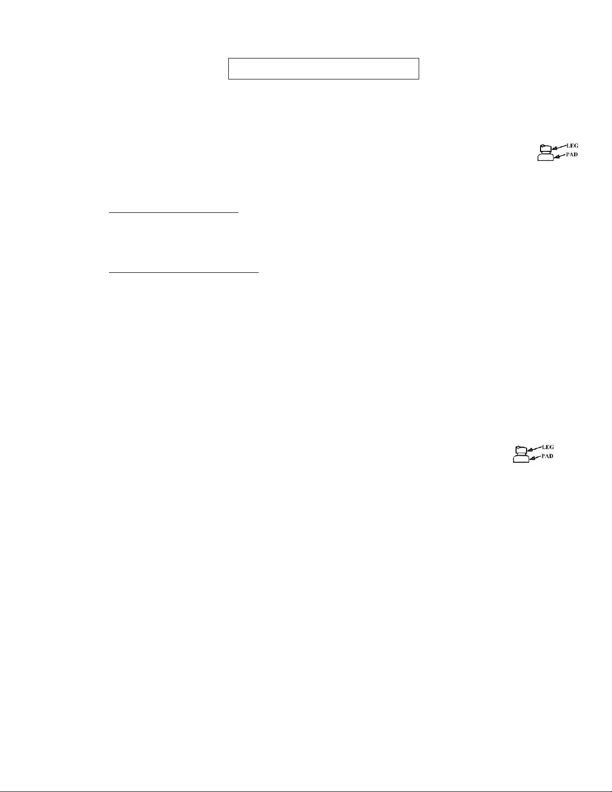
2) Place the Anti-Vibration Pads under each leg of the Pulper and Hydra-Extractor®.
3) TRAY FEED UNITS ONLY - Install the tray to the Pulper (if it was not already installed at the
factory) using the provided gasket material and hardware.
4) TROUGH FEED UNITS ONLY - Install the provided trough gasket between the Pulpers
inlet and the trough outlet and secure with the provided hardware.
UDT MODELS:
1) Cut a hole in the top of the table as shown in the Installation Drawing using the following
diameter: SPC-75S Pulper - 22" Diameter hole
2) Center the provided UDT Cone beneath the opening and weld it into place as shown.
Please follow print detail for welding instructions.
3) Put the Pulper into position.
4) Place the anti-vibration pads under each leg of the Pulper and Hydra-
Extractor®.
5) Install the UDT gasket onto the Pulper tank and around the outside of the adapter cone.
*see image on next page
6) Adjust the Pulper and Hydra-Extractor®legs so that the rubber UDT gasket provides a
water tight seal with 2” clearance between Pulper and table.
7) Install the provided trough gasket between the Pulpers inlet and the trough outlet and
secure with the provided hardware.

MOUNTING OF THE GRABBER MAGNETS:
Preferred: Locate per detail below and weld into place.
Optional: Drill four 7/32” diameter holes into the trough as shown below. Seal the heads of
the provided screws with silicone and attach the magnet.
RECOMMENDED POSITION OF THE GRABBER MAGNETS

MOUNTING DETAIL OF TROUGH

PIPING INSTALLATION
1) PIPING FOR FRESH WATER LINES AND DRAIN LINES NOT SUPPLIED BY SOMAT
®
.
2) PIPE SIZES TO BE IN ACCORDANCE WITH SOMAT
®
RECOMMENDATIONS.
3) ALL FITTINGS MUST BE PRESSURE RATED DRAINAGE TYPE.
4) KEEP DRAINS ACCESSIBLE TO UNIT. DO NOT INSTALL DRAINS UNDER SOMAT
®
EQUIPMENT.
5) NO EXTERNAL STRAIN TO BE EXERTED ON SOMAT
®
EQUIPMENT.
6) PROTECT ALL SOMAT
®
EQUIPMENT AND PIPING FROM FREEZING AND
CONDENSATION.
7)
ALL PIPING TO BE IN ACCORDANCE WITH STATE AND LOCAL PLUMBING CODES.
8)
“F” = FURNISHED BY SOMAT / “NF” = NOT FURNISHED BY SOMAT
FRESH WATER:
*NOTE: In Massachusetts, the Public Water Supplier shall be contacted regarding the proper
backflow prevention device to be installed. *
1) Bring a 1/2" cold water line for theSPC-75S, to the pre-piped fresh water assembly. (See
enclosed diagram and Installation Drawings)
2) Bring a 1/2" hot water line to the pre-piped fresh water assembly on the Hydra-Extractor
(see enclosed diagram and Installation Drawing).

HYDRA-EXTRACTOR®OVERFLOW AND PULPER DRAIN:
1) Install 1-1/2" pipe from the Hydra-Extractor®overflow to floor drain (DO NOT REDUCE).
2) Install 2" pipe from the Pulper drain to floor drain (DO NOT REDUCE).
RETURN PIPING FOR UNITS WITH A TRAY FEED ONLY:
1) Install the pre-piped return water assembly onto the return pump (if not already factory
installed) (see enclosed diagram and Installation Drawings).
2) Install one side of the provided tubing over the return water elbow on the feed tray and
the other side onto the pump return water assembly (if not already factory installed).
3) Install the provided hose clamps at each connection.
RETURN PIPING FOR UNITS WITH A TROUGH:
1) Pipe from the return pump to the supplied trough end flush nozzle and silver saver
connections as well as to the optional trough nozzles as shown in the trough detail on the
Installation Drawing using the provided throttling gate valves
NOTE: All Pre-Piped Assemblies are hand tightened for shipping purposes only.

ELECTRICAL INSTALLATION
1)
PRE-WIRED CONTROL PANELS, OPERATOR DEVICES & ELECTRIC VALVES BY
SOMAT.
2)
INSTALL CONDUITS FROM PANEL TO PREWIRED JUNCTION BOX, PULL
MOTOR WIRES AND CONTROL WIRES THRU SEPERATE CONDUIT AND DO THE
FINAL TERMINATIONS.
2) GROUND ALL ELECTRICAL EQUIPMENT.
3) CONTROL CIRCUIT TO BE 115 VAC AND/OR 24VDC NOMINAL.(SEE APPROVED
DRAWINGS)
4) ALL SOM-A-TROL PANELS ARE TO BE WIRED IN ACCORDANCE TO LOCAL,
STATE AND/OR NATIONAL ELECTRIC CODE (NEC 1993) SPECIFICATIONS.
5) INTEGRAL PUSH BUTTONS ARE LOCATED IN PANEL DOOR AND PRE-WIRED AT
FACTORY. OPTIONAL REMOTE PUSH BUTTON STATION IF SUPPLIED; TO BE
MOUNTED & WIRED AT WORK STATION BY ELECTRICIAN. (BRACKET
REQUIRED BY CUSTOMER).
PANEL & OPTIONAL REMOTE PBS MOUNTING:
1) Mount the Som-A-Trol®in a suitable location (see Installation Drawings) so that the
bottom of the panel is at least 42" above the finished floor or in accordance with
ADA requirements.
2) Install the Optional Remote Push Button Station onto the Dish Table or at another
convenient location. (See Diagram and Installation Drawings.)
MOUNTING PATTERN FOR THREE HOLE PUSH BUTTON STATIONS

SUPPLYING THE SOM-A-TROL®WITH POWER
Bring the (4 wire) customer power supply to the top right side of the Som-A-Trol®
and connect to the panel disconnect and ground lug. (See Diagram and
Installation Drawings.)
All close couple systems are prewired; there is a prewired junction box mounted
to the side of the extractor shell. Inside this prewired junction box there will be
terminals that are the same as in the panel. Install conduits from the panel to the
pre-wire junction box, pull the motor wires and control wires thru these conduits
separately and do your final wire terminations matching numbers from panel to
pre-wire junction box.
REMOTE PUSH BUTTON STATION
Mount the remote push button station, run the conduit from the remote push
button station to the prewired junction box then pull the wires from the remote
push button station to the prewired junction box and do your final hookups in the
prewired junction box.
WARNING:
Improper connection of the equipment grounding conductor can result in a risk of
electrical shock. An equipment grounding conductor must be run with the circuit
conductors and connected to the pulper/extractor grounding terminal.
This manual suits for next models
1
Table of contents
Other Somat Industrial Equipment manuals


Popular Industrial Equipment manuals by other brands

Vertiv
Vertiv Liebert MCV Series Installer/user guide

Aerotech
Aerotech ABRS Series manual

hager
hager tehalit.FWK Plus Mounting instructions

Schmalz
Schmalz VCBL-G-K1 operating instructions

Redline Engineering
Redline Engineering 500HWC manual

Lennartsfors
Lennartsfors IronHorse IH 2055 Classic Operator's manual


HYDAC FILTER SYSTEMS
HYDAC FILTER SYSTEMS LVU-CD-10 Operating and maintenance instructions

Humboldt
Humboldt PROMAT HM-4187H product manual

RAIMONDI
RAIMONDI BULLDOG ADV Use and maintenance manual

Schwarz
Schwarz SB10B operating instructions

Panduit
Panduit JBP1D installation instructions

ABB
ABB VTC304-13 Operation manual