Foldawheel Draco User manual

V2.0
User Manual
Draco

TABLE OF CONTENT
PARTS INTRODUCTION
01
Title Page
Parts Introduction 01
1.0 Safety Tips 02 - 03
2.0 Set Up Upon Arrival 04
3.0 Adjustments 05 - 07
4.0 Operation 08 - 09
5.0 Control System 10 -14
6.0 Maintenance 15
Contact Us 15
01. Headrest
02. Backrest
03. Armrest
04. Side Panel
05. Recline Actuator
06. Motor/Differential Gear
07. Anti-Tipper Wheel
08. Rear Wheel
09. H-belt
10. Joystick
11. Seat Cushion
12. Knee Belt
13. Calves Cushion
14. Footrest
15. Swing Castor
16. Front wheel
01
02
03
04
05
06
07
08
15
16
10
13
12
14
09
11

02
1.0 SAFETY TIPS
1-1.1. Standing up stresses your body in ways you may not be used to. Therefore we
recommend you consult your doctor or physical therapist before using the
stand-up wheelchair.
1-1.2. Before using the standing wheelchair, it is absolutely vital that the
knee support, safety belt and chest belt are xed correctly.
Switch on the master power switch before using. (see P9)
- Before using the standing wheelchair, you should be familiar with the operation
and the function.
- Use only on standard household, hard and even ground. Not to be used on wet
surface.
- In case of staircase, the standing wheelchair must be carried by 4 persons.
- When getting on or off the stand up wheelchair, do not put the foot on the
footplate, to avoid danger.
1-1. Standing
Attention :
Warning: Maximum weight should not exceed. 250 lb.(120 kg)
DO NOT DRIVE OVER UNEVEN GROUND!
Danger of tipping over!
DO NOT LEAN OUT OF THE RAISED VERTICALIZER!
Danger of tipping over!
NEVER DRIVE ON ASCENDING OR DOWNWARD SLOPES
WHEN THE VERTICALIZER IS RAISED!
Danger of tipping over!
NEVER REACH INTO THE MOVING APPARATUS OF THE
RAISED VERTICALIZER!
Danger of crushing!
1-2. Important point to note for operating the wheelchair
The following actions should not be attempted:

03
* Only ever drive downhill at a maximum of 1/5 of the top speed! Avoid abrupt
braking or acceleration on gradients.
* If at all possible, avoid driving on slippery surface (such as gravel) where there is a
danger of you losing control over the wheelchair, especially on a gradient! If driving
on such a surface is inevitable, then always drive slower and with the utmost caution.
* Never attempt to overcome an obstacle when on an uphill or downhill gradient!
* Never attempt to drive up or down a ight of steps with your wheelchair!
* Always approach straight on! Ensure that the front wheels and rear wheels move
over the obstacle in one stroke! Do not stop halfway! Do not exceed the maximum
obstacle height!
* Avoid shifting your center of gravity, or abrupt joystick movements and
changing of direction when the wheelchair is in motion!
* Never use the wheelchair to transport more than one person!
* Note that the wheelchair will brake or accelerate if you change the Driving Mode
whilst the wheelchair is in motion!
Always practice with your Healthcare professional or attendant. Before attempting
to negotiate curbs, inclines or ramps alone., it is important for you to develop a safe
technique that is suitable to your abilities.
1-3. Safety Information on Driving and Free wheel Mode
1-4. Rear Wheels
Danger of injury if the wheelchair tips over
Curbs, inclines and ramps
Never lift the wheelchair by the ip-back armrests. These parts are detachable and
lifting the wheelchair by them may cause damage to the chair or injury to the user.
1-5. Armrests
Flip-back armrests
Power stand up wheelchair does not advocate the use of power drive attachments on
any power wheelchair. Use of a power drive attachment on wheelchair alters its
intended use. Installation of a power drive attachments is considered an alteration to
the frame and voids the warranty.
1-6. Power Drive Attachments
Marketing any unauthorized modications or using parts not supplied by
technical personnel may change the whelchair structure and create an unsafe
condition, thus voiding the warranty.
1-7. Modifications
Doing a “wheelie”(tilting the wheelchair backward to its balance point) can be dangerous.
Do not attempt this maneuver without an attendant.
Warning :
1.0 SAFETY TIPS

~ Power stand up wheelchair, joystick, heel strap & chest belt
~ Knee support & headrest
~ Charger
~ User manual, oil pot and tool
~ Options as ordered
Remove any transport straps or transport guards.
2-1. The Original Package And Accessories
2-2. Unfolding The Stand Up Wheelchair
The Original Package And Accessories Contain The Following Components :
~ Lay down the backrest and tighten the knobs on the left and right.(P1,P2)
~ Swing the backrest and armrest forward, lift the side panel up.(P3)
~ Tighten (not too tight) the screw for pull rod of the armrest.(P4)
~ Tighten (not too tight) the screw of the actuator.(P5)
~ Assemble the headrest.(P6)
Backrest Assembly Instructions :
2.0 SET UP UPON ARRIVALS
P5 P6
04
Set-up Video QR Code

3.0 ADJUSTMENTS
Should you require adjustments and alterations to the mechanism of the wheelchair,
or any maintenance work, please contact qualified technicians.
- Use the controller to raise the seat a little bit.(P7)
- There are 4 screws on both side that need to be remove in order to adjust the
seat depth. Remove the bottom 2 screws on both side, then pull the inner tube
out to extend the seat depth(P7~8). Put back the screws when you get your
desire seat depth.
- Remove the top 2 screws and repeat the steps, make sure the length of top and
bottom is the same.(P10)
Theheightofthefootrestisadjustableandshouldbealteredinlinewithyour
bodyproportionstoguaranteethebeststandingpositionpossible.Footrest
adjustmentshouldalsotakeintoaccountyourchoiceofseatcushion.(P10~11)
- Aftertakingoutthescrews(bothsides),thefootrestheightcanbeadjusted
bysecuringondifferentholes.Eachholesare1.8cmdifference.
- Retightenthescrewsatyourdesireheight.
3-1. Adjusting The Seat Depth
3-2. Adjusting The Footrest Height
P7 P8 P9
P10 P11
05

3-3. Adjusting The Footrest Angle
3.0 ADJUSTMENTS
3-5. Chest Belt
- By removing the top screw (left and right) , the footrest has 3 adjustable angle
(P12, 13 & 14)
- Retighten the screws once you get desired angle.
P12
P15
P16
P17
P13 P14
-Makesurethatthechestbeltissecuredonthe
backrestʼsvelcrostrap.
-Thechestbeltistoholdtheupperbody(chest)
inplace.
3-4. Knee Support And Belts
3-4-1. Knee Belt
The most important safety features of the stand-up wheelchairs are the knee
support, safety belt and chest belt. It is absolutely essential that these are correctly
in place before you attempt to stand up.
The knee support holds the knees in an extended posture and prevents you from
slipping out from the wheelchair while standing up.
Attach the one of the triangular clasp of the knee belt
onto the side of the frame.
Center the knee belt in front of your knee, pull the
velcro belt until it is sitting firmly in place, then attach
the other clasp onto the frame. Knee belt should be
just below (not right on) the knee cap and not too tight.
06
Low Medium High

P18
P20
P19
P21
3-5-2. Safety Belt
3-5-1. H-Belt
- The safety belt holds the waist in place.(P20)
-Make sure that the safety belt is secured on the the backrest’s velcro .
- Close the catch on the safety belt and pull it but not too tight.(P21)
-To release the safety belt., simply press the red button in the center of the catch.
- The H-belt holds the upper body in place.(P18)
- Close the catch on the belt and pull the strap to tighten. (not too tight)(P19)
-To release the safety belt, press the top and bottom part of the center of the catch.
3.0 ADJUSTMENTS
07
3-6. Adjusting The Armrest
B
A
1
3 4
2
1) Remove A screws and loosen B screws.
2) Adjust the Armrest to the desired height.
3) Secure screws A
4) Tighten screws B

4.0 OPERATION
4-1. Before Driving for the First Time
Make sure :
- Before you take your first trip, you should familiarize yourself with the
operation of the vehicle and with all operating elements. Take your time to
test all functions and driving modes.
- Your electric wheelchair is able to overcome obstacles and curbstones to
a maximum height of 5 cm.
- When driving in standing position, speed is limited to 1/5 of the
maximum speed.
4-3. Driving up and down gradients
Your electric wheelchair has a maximum tilt-resistant climbing ability of
10 degrees.
* You are within easy reach of all operating controls.
* The battery charge is sufficient for the distance intended to be covered.
* The restraining belt is in perfect order.
Warning :
* Never approach obstacles at an angle!
* Put your backrest into an upright position before climbing an obstacle!
* Never drive over obstacles with an erected vertical(standing position).
* Only ever drive obstacles at a maximum of 1/5 of the top speed! Avoid abrupt
braking or acceleration on gradients.
Warning :
* Only ever drive downhill at a maximum of 1/5 of the top speed.
* Avoid sudden changes of direction or abrupt braking when driving on slopes.
* Always return the backrest of your seat to an upright position before ascending
slopes. We recommend that you recline the seat backrest slightly to the rear
before descending slopes.
* If the footrest is raised, drive mode is only used for positioning and not for regular
drive operation. Lower the footrest before ascending a slope.
* Never attempt to ascend or descend a slope on slippery surfaces or where there
is a danger of skidding.
* Avoid trying to get out of the vehicle from an incline or a gradient.
* Always drive straight in the direction of the road or path you are going,
rather than attempting to zigzag.
* Never attempt to turn around on an incline or a slope.
Danger :
* When the seat is raised, drive operation only serves positioning, not driving.
* Never driven over uneven ground on an upward or downward slope obstacles.
08
4.0 OPERATION
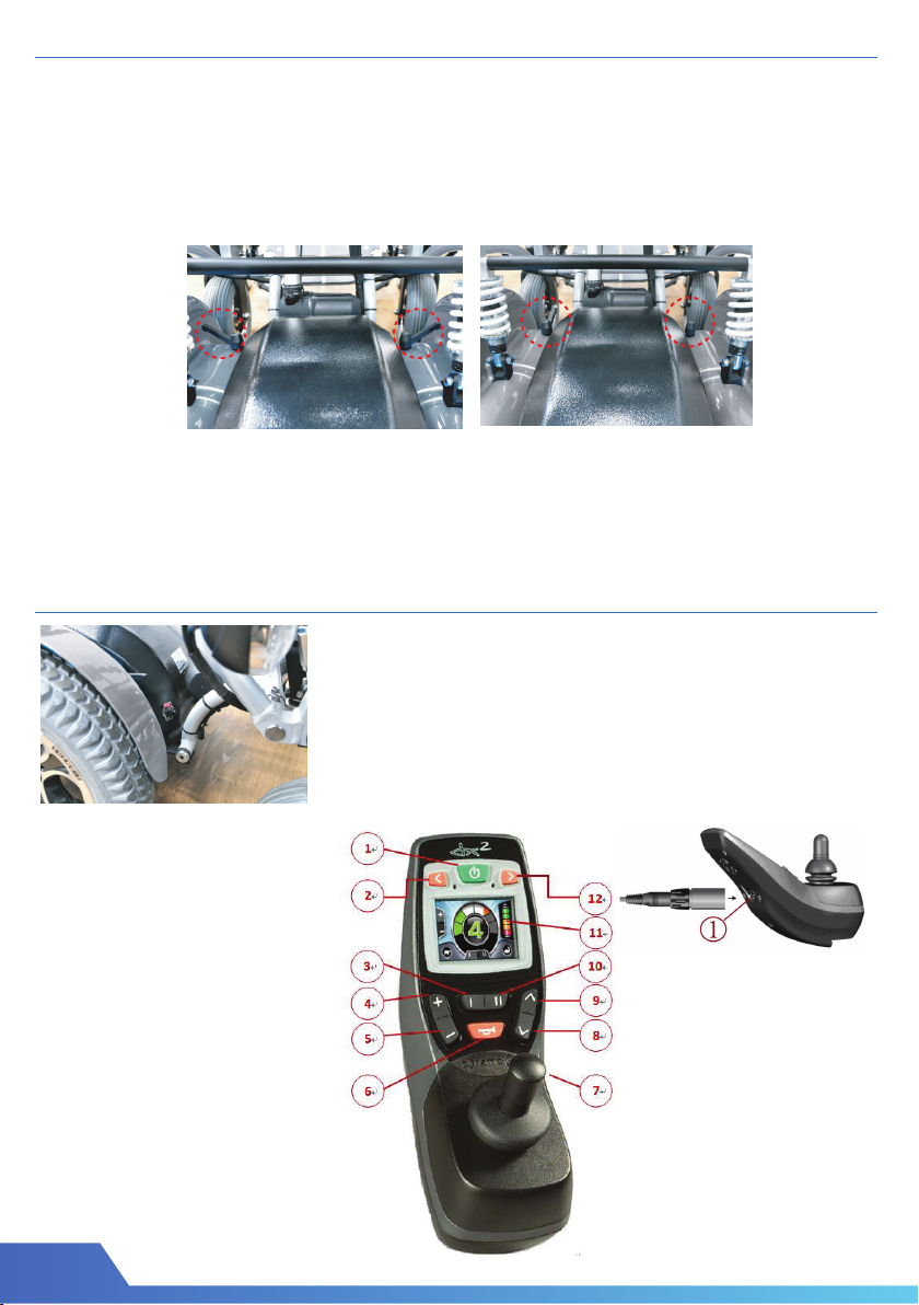
4-4. Free Wheel
The motors are designed to engage the electromagnetic brakes
when the vehicle is not in use or when the power is OFF. There is also a
manual feature that allows the unit to “freewheel”. Free-wheeling is
accomplished by pulling the free-wheeling levers to the free-wheeling position.
(P22~23)
Warning :
* Never free-wheel your power wheelchair on a slope.
* Never free-wheel the motors while operating your vehicle.
* Always remember to engage the motors before turning the power back ON.
09
5.0 CONTROL SYSTEM
Master Power Switch
* Switch on the master power before using.
The Dynamic DX2 Remote
Assembly of the remote
1. ON/OFF
2. Left indicator button
3. Function keys I
4. Drive profile selection +
5. Drive profile selection -
6. Horn
7. Joystick
8. Accessory mode selection
9. Accessory mode selection
10. Function keys II
11. Screen
12. Right indicator button
Lower Side
1.Combined charging socket/
programming socket
P22 P23

10
5.0 CONTROL SYSTEM
5-1. Battery and Control Connection
The main electrical system is composed of the motor, control box battery and
controller. The connection of control systerm as below :
5-2. Battery Charger
1. First, the battery charger line connect to the battery DC power socket and make
sure the line is right connect.
2. Connect the AC power line to the AC socket. (110~ 230V)
3. The light of bettery charger from yellow color become green color and represent
the battery charge is finish.
*When the battery capacity is empty power, it will stop working.
Battery full
Battery almost full
Battery half full, drive towards a charger
Battery low, recharge soon
Battery almost empty, recharge now
Battery empty, recharge immediately
11
5.0 CONTROL SYSTEM
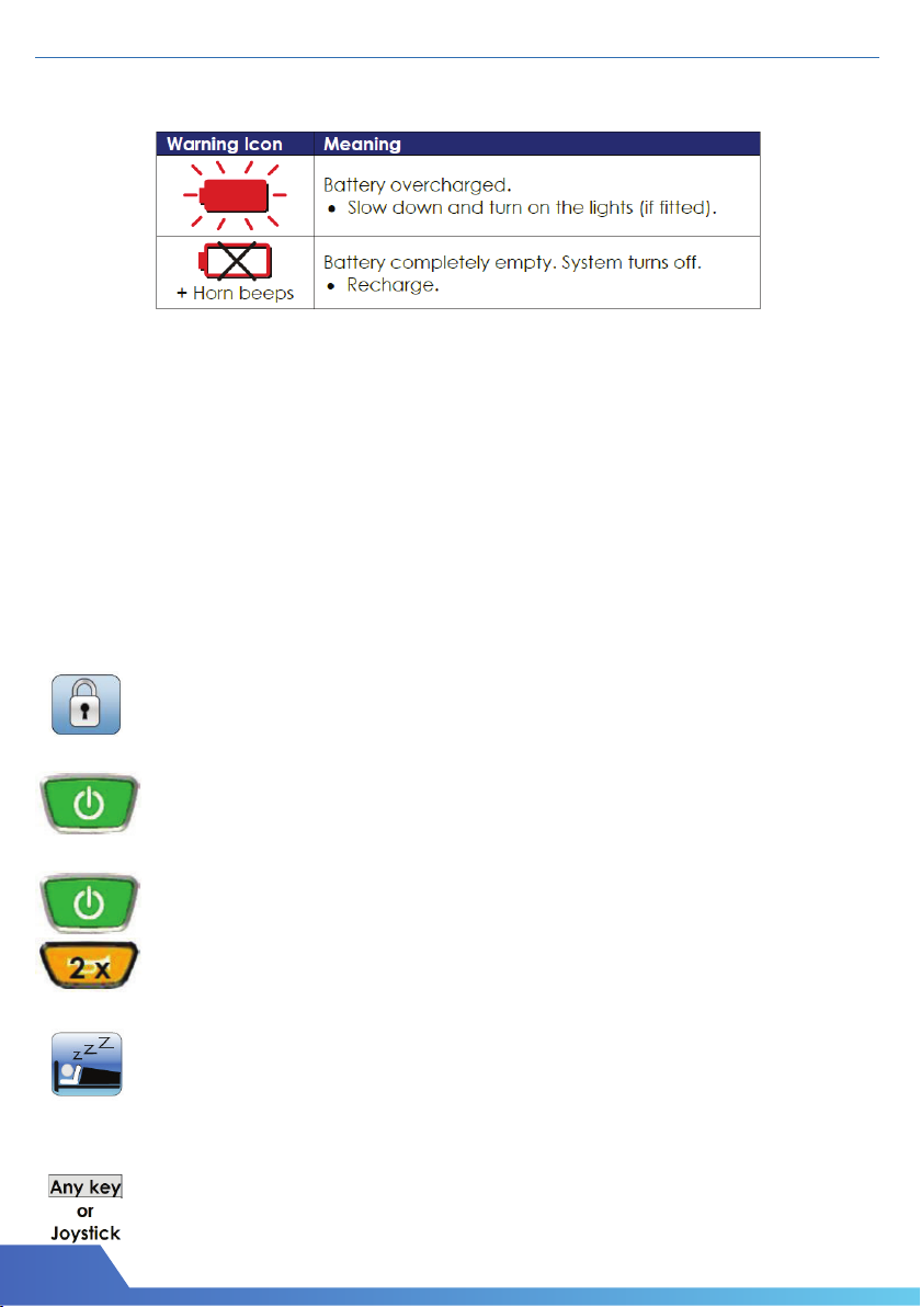
Battery Warnings
Battery warnings are shown at the centre of the screen, in the”Active Mode” area.
Attention :
1. Anytime check the battery capacity.
2. New battery must be charged over 8 hours.
3. Charge your battery from the battery charger provided by manufacturer only.
5-3. Main Circuit Breaker
5-4. System Lock / Unlock & Sleep Mode / Wake Up
To Lock The DX System
To Unlock The DX System
Sleep Mode
To Wake Up the DX System
The mean circuit breaker reset button is located on the battery box.
The main circuit breaker monitors the electric current drawn from the battery.
It is a safety feature built in your wheelchair for your extra safety.
The entire electric system of the wheelchair is protected by the main circuit breaker
against overloading.
If the Lock Enable parameter is set to “YES”, the sytem can be locked
by pressing the power button for more than 4 seconds.
Press the power button for 4 seconds when the DX System is turned
on . The DX system will turn off in locked state.
If the Sleep Mode Enable parameter is set to “YES”, the DX system will
go to sleep after a period of inactivity. This period can be set with the
Sleep Timeout parameter. When the DX system sleeps, it is partially
turned off to reduce energy consumption.
Press any button on the AJR, or, if the Enable Joystick Wakeup
parameter is set to “YES”, move the joystick.
The DX system will turn on.
Press the power button.
The AJR will show a lock on the display.
Press the horn button twice within 10 seconds.
The DX system will turn on normally.

12
5.0 CONTROL SYSTEM
5-5 Standard Menu Navigation
Drive Mode - Standard
The colour of the current Drive Profile, shown in the middle of the screen, is depends on
the chair’s status.
A green Drive Profile shows a normal drive operation.
An orange Drive Profile is displayed to indicate that a chair can drive,
or is driving in a restricted capacity - that is, reduce speed.
A red (flashing) Drive Profile indicates that the chair is in an inhibited
state - the chair cannot be driven in this state.
*NOTE :
When the backrest is reclined >15° in standing position, the drive mode will not function
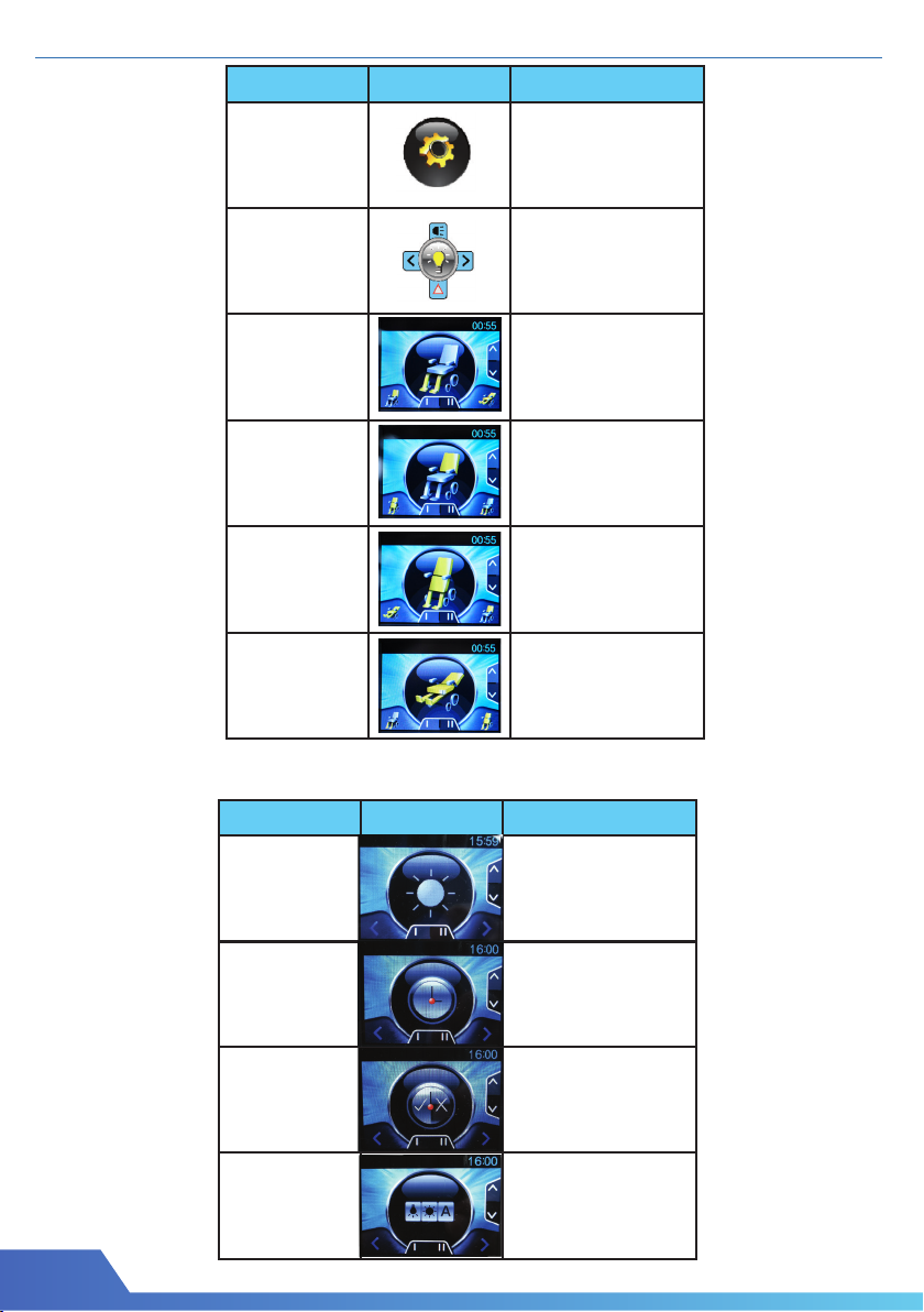
5-6. Accessory Mode - Standard
Accessory Modes are availble :
* When the presence of that accessory is detected in the DX system.
* When the menu of that accessory has been enabled with its corresponding
menu enable parameter.
When the Accessory Mode button is pressed (either Next or Previous) the menu
will always start at the Seating Accessory screen (if actuators are active).
13
Mode
Program
Screen
Setting
Light
Footrest
Raisable
Function
Recline
Function
Standing
Function
Lay down
Function
Screen
Brightness
Tilt the joystick left
and right to adjust
the brightness of the
screen
The clock in the
screen can be
adjusted by using the
joystick.
User can decide
whether to show the
time or not
The background can
be switch between
day mode, night
mode or auto mode
Time
Adjustment
Show
Time
Backgroud
Colour
OBP-change screen
brightness, clock, time
and clock visibility
Light-activate lights
and indicators
Pull the joystick
backward to raise the
footrest, push forward
to lower it down
Pull the joystick
backward to recline
the backrest, push
forward to raise
Push the joystick
forward to stand up,
pull backward to get
back into sitting
position
Pull the joystick
backward to lay down,
push forward to get
back into sitting
position
Active Function(s)
Mode Active Function(s)
5.0 CONTROL SYSTEM
Program Screen Setting

14
5.0 CONTROL SYSTEM
5-7. Flash Codes
Flash codes indicate the nature of an abnormal condition directly from DX2
information Gauge. Without the use of any servicing tools, the condition can be
diagnosed easily.
Flash
Code
1.
2.
3.
4.
5.
6.
7.
8.
9.
10.
11.
12.
Description
DX Module
Fault
Temperature
Fault
Left(M1)
Motor Fault
Right(M2)
Motor Fault
Left(M1)Park
Brake Fault
Low Battery
Fault
Over Voltage
Fault
CANL Fault
CANH Fault
Stall Timeout
Fault
Module
Mismatch
Right(M1)
Park Brake
Fault
Suggestion
Reprogramming the wheelchair system may correct this problem .
Consult your Dynamic Service Centre.
Turn the DX system off then on again.
Check DXBUS connections and replace where neccessary.
Disconnect the M2 plug and check continuity between the two
Positronic Park Brake pins. Ensure there is no continuity between motor
and park brake terminals.
Disconnect the M1 plug and check continuity between the two
Positronic Park Brake pins. Ensure there is no continuity between motor
and park brake terminals.
Disconnect the right motor plug and check continuity between the
motor pins on M2. Ensure there is no continuity between motor and
park brake terminals.
Disconnect the left motor plug and check continuity between the motor
pins on M1. Ensure there is no continuity between motor and park
brake terminals.
Turn system off, wait for a few minutes for the system to stabilize, and turn system
back on. If fault re-occurs, consult your Dynamic Service Centre.
Check the continuity of the DXBUS cable.
Check for shorts between DXBUS pins. An open or short circuit on
another DX Module can cause this fault.
Check battery connection and terminals. The battery voltage should be
similar when the battery is on charge, and when it isn’t. Check that fuses
have not blown, or circuit breakers tripped. Replace battery if worn out or
capacity is insufficient for the user’s needs
If this fault occurs during battery charging, the battery charger is defective or
incorrectly adjusted. Check the battery charger’s open circuit voltage is in
accordance with the battery manufacturer’s limits, and is less than 32V .
Check that the battery wiring & terminating is secure.
Turn the DX system off then on again. The system may require to cool
down. Ensure wheels turn freely while under no load. Have motor(s)
checked by a service technician.
Check the continuity of the DXBUS cable.
If the Hazard Lights were already switched on when the DX system was turned on,
Flash Code 10 and Limp Mode (slow driving) may result. To clear this fault, turn
the Hazard Lights off, then turn the DX system off then on again.
If generated by a Kill signal, the cause of the fault is serve.

6.0 MAINTENANCE
When cleaning your Standing Wheelchair use a dry or slightly moistened
cloth to wipe the wheelchair down. For stubborn or oily stains, apply a mild
detergent to the cloth. Do not hose down your wheelchair with water.
Check the state of the tread on the tyres every one to six months. If a tyre is heavily
or unevenly worn, it should be replaced.
According to frequency of use, lubricate the joints once a week and once
a month. (Joints shown below)
Wheelchair88 Ltd
wheelchair88.com
+60-3-3318 3133
Advanced Mobility Technology
@WheelChair88
Popular Mobility Aid manuals by other brands


AmeriGlide
AmeriGlide HERCULES II 600 Series owner's manual

Invacare
Invacare Matrx MX1 manual

Drive DeVilbiss Healthcare
Drive DeVilbiss Healthcare 10306AT-6 instruction manual

Medline
Medline GUARDIAN MDS86800XW User instructions and warranty

aidapt
aidapt Solo Bed Transfer Aid Fixing and maintenance instructions

Circle Specialty
Circle Specialty Klip Series user manual