Follett FZR8-PC User manual

0 01468818R00

1
Welcome to Follett
Follett equipment enjoys a well-deserved reputation for excellent performance, long-
term reliability and outstanding after-the-sale support. To ensure that this equipment
delivers the same degree of service, we ask that you review the installation protion of
this manual before beginning to install the unit.
Our instructions are designed to help you achieve a trouble-free installation. Should
you have any questions or require technical help at any time, please call our Technical
Service Group at (877) 612-5086 or (610) 252-7301
Before you begin
After uncrating and removing all packing material, inspect the equipment for
concealed shipping damage. If damage is fopund notify the shipper immediately and
contact Follett LLC so that we can help in filing the claim, if necessary.

2

3
Safety Precautions
THIS MANUAL HAS BEEN PREPARED FOR PERSONNEL QUALIFIED TO INSTALL, MAINTAIN
AND REPAIR ELECTRICAL REFRIGERATION EQUIPMENT, WHO SHOULD PERFORM THE
INITIAL FIELD STARTUP AND ADJUSTMENTS OF THE EQUIPMENT COVERED BY THIS
MANUAL.
READ THIS MANUAL THOROUGHLY BEFORE OPERATING, INSTALLING, PERFORMING
MAINTENANCE ON, OR REPAIRING THE EQUIPMENT.
WARNING Failure to follow all the instructions in this manual can cause property damage
or serious injury.
WARNING Improper installation, adjustment, alteration, service, or maintenance can cause
property damage or serious injury.
WARNING Electrical connections should be performed only by qualified persons.
Electrical and grounding connections must comply with the applicable portions of the
National Electric Code and/or all local electric codes. Failure to comply with this procedure
can cause property damage or serious injury.
WARNING Before connecting the unit to the electrical supply, verify that the electrical and
grounding connections comply with the applicable portions of the National Electric Code
and/or other local electrical codes. Failure to comply with this procedure can cause property
damage or serious injury.
WARNING Before connecting the unit to the electrical supply, verify that the electrical
connection complies with the specifications on the data plate. Failure to comply with this
procedure can cause property damage. or serious injury.
WARNING Appliance must be connected to a grounded circuit per electrical codes.
WARNING Appliances equipped with a flexible electric supply cord, require a NEMA L15-
30 grounded plug (Not included). It is imperative that this plug be connected into a properly
grounded receptacle. Failure to comply with this procedure can cause property damage or
serious injury.
WARNING If the receptacle is not of the proper grounding type, contact an electrician. Do
not remove the grounding prong from the plug. Failure to comply with this procedure can
cause property damage or serious injury.
WARNING Before performing any service that involves electrical connection or
disconnection and/or exposure to electrical components, always perform the Electrical
LOCKOUT/TAGOUT Procedure. Disconnect all circuits. Failure to comply with this procedure
can cause property damage or serious injury.

4
WARNING Before removing any sheet metal panels, always perform the Electrical
LOCKOUT/TAGOUT Procedure. Be sure all circuits are disconnected. Failure to comply with
this procedure can cause property damage or serious injury.
WARNING Do not operate this equipment without properly placing and securing all covers
and access panels. Failure to comply with this procedure can cause property damage or
serious injury.
WARNING Do not use or store gasoline or other flammable vapors or liquids in the vicinity
of this or any other appliance. Failure to comply can cause property damage or serious injury.
WARNING In the event of a power failure, do not attempt to operate this appliance. Failure
to comply can cause property damage or serious injury.
General Safety
WARNING Follett accepts no responsibility for any situation resulting from work carried
out in an unprofessional manner, or from the incorrect interpretation or application of
regulations.
General Installation
WARNING Incorrect installation or any modifications made to the appliance may damage
property or serious injury.
Electrical
WARNING Electrical connections or any work required on the electrical circuits inside the
appliance must be performed by certified technicians in compliance with local, state, and
federal regulations.
WARNING Make sure all facility electrical connections follow all local and federal electrical
codes and regulations.
Inspection and Maintenance
WARNING Appliance maintenance must be carried out by only by qualified personnel.
WARNING Before any maintenance work is performed, the appliance must be
disconnected from the electrical supply. Apply a lockout tag to the power cord.
WARNING All replacement parts that are not supplied by Follett must be pre-approved
before installation.
Repair Work Safety
WARNING Repair work must only be performed by Follett approved distributors or one of
its authorized representatives. Follett accepts no responsibility for any situation resulting
from work performed by untrained and/or unauthorized personnel.

5
WARNING
ELECTRICAL LOCKOUT/TAGOUT PROCEDURE
The Electrical LOCKOUT/TAGOUT Procedure is used to protect personnel working on an
electrical appliance. Before performing any maintenance or service that requires exposure to
electrical components.
➢Power down the unit by pushing the “Standby” icon as shown in (3.1.3)
➢Disconnect appliance power cord from electrical outlet
➢Place a tag on the cord to indicate that unit has been disconnected for service
and power should not be restored until tag is removed by servicing personnel.

6
Table of contents
1. STANDARDS AND GENERAL WARNINGS................................................................................... 6
1.1 TESTING AND INTENDED USE.................................................................................................. 7
1.2 INTRODUCTION........................................................................................................................... 7
1.3 PRODUCT DESCRIPTION........................................................................................................... 8
1.4 CERTIFICATION........................................................................................................................... 8
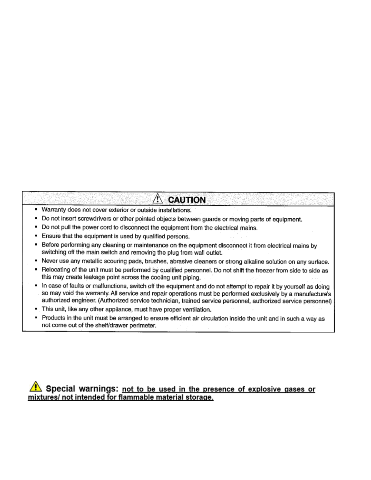
1.5 GENERAL SAFETY WARNINGS................................................................................................. 8
1.6 CUSTOMER’S RESPONSIBILITIES .......................................................................................... 10
1.7 CUSTOMER SERVICE REQUESTS .........................................................................................10
1.8 ORDERING OF SPARE PARTS ................................................................................................ 10
1.9 PRODUCT CONFIGURATION................................................................................................... 10
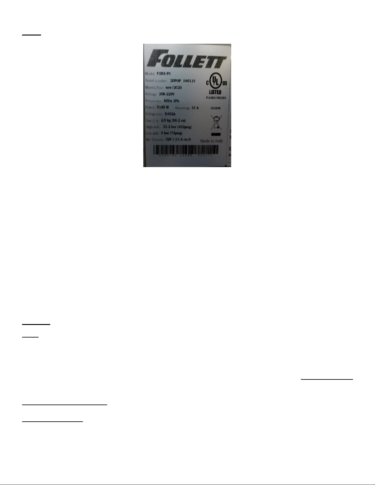
1.10 MATERIALS AND REFRIGERANTS ....................................................................................... 10
1.11 WARNING LABELS.................................................................................................................. 12
2. INSTALLATION............................................................................................................................. 13
2.1 TRANSPORTATION AND HANDLING ...................................................................................... 13
2.2 POSITIONING............................................................................................................................12
2.3 WIRING AND ELECTRICAL HOOK-UP..................................................................................... 15
2.4 SET UP OPERATIONS .............................................................................................................. 15
2.5 AIRFLOW REQUIREMENTS ..................................................................................................... 16
2.6 RE- LOCATION...........................................................................................................................16
2.7 SCRAPPING AND DISPOSAL...................................................................................................16
2.8 REMOTE ALARM CONNECTION.............................................................................................. 17
3. OPERATION / OPERATIONAL GUIDANCE....................................................................................16
3.1 STARTING CYCLE......................................................................................................................19
3.1.1 TIME CYCLE........................................................................................................................ 19
3.1.2 PRODUCT TEMPERATURE CYCLE.................................................................................. 19
3.1.3 COMPLETION OF PROCESSING / END OF SHIFT…………………………………………20
3.2 USER MENU................................................................................................................................ 22
3.2.1 USB OPTION ........................................................................................................................23
3.2.2 I/O STATUS...........................................................................................................................24
3.2.3 HACCP DOWNLOAD............................................................................................................ 24
3.2.4 USING A PROPERTY SOFTWARE TO TRACE HACCP DATA......................................... 25
3.2.5 ACCESS THE SOURCE HACCP FILES ............................................................................. 28
4. BASIC SERVICE DIAGNOSTIC ......................................................................................................30
4.1 ALARM CODES...........................................................................................................................30
4.2 ALARM CODE DETAILS............................................................................................................29
5. DEFROST.........................................................................................................................................30
6. CLEANING / INSPECTION...............................................................................................................30
7. TFT DISPLAY SOFTWARE UPDATE PROCEDURE.......................................................................31
8. CALIBRATING THE TFT SCREEN..................................................................................................32

7
1. STANDARDS AND GENERAL WARNINGS
PRODUCTS APPLICABLE TO THIS MANUAL
The manual is exclusively valid and applicable to the following product:
Plasma Freezer
Adjustable temperature control range: lowest T = -40°F/°C, highest T = -22°F(-30°C)
Operating temperature: -40°F/°C
Factory pre-set to: -40°F/°C
Model: FZR8-PC
Environmental Operating Conditions
- Ambient temperature operating range: 50°f (10°C) ~104°f (40°C)
- Electrical supply: 220v/60Hz/3ph
- Usage: This product is intended for use indoors only.
Model
Number
W
D
H
Setpoint
Temp.
Elec. V/Ph/Hz
Refrigerant
(quantity)
FZR8-PC
31 ½ in
(80 cm)
32 7/8 in
(83.5 cm)
77 5/16 in
(196.4 cm)
-40°F/°C
220V/3/60
R452A (88.2OZ)

8
Note: All relevant data referring to this product can be found on the data label visible on the rear part
of the cabinet. Here is an example of the label:
1.1 TESTING AND INTENDED USE
This equipment is tested in compliance with established regulations and then shipped ready for use.
This product is intended for use:
•As a rapid freezer in research use.
•As a medical device for freezing samples for diagnostic use.
•As a medical device for freezing biological components.
This Product is not intended for long-term storage.
Registration: This medical application is considered a Class II medical device by the FDA.
“If the equipment is used in a manner not specified by the manufacture, the protection
provided by the equipment may be impaired.”
1.2 INTRODUCTION
This manual provides instructions required for the proper use of the equipment and to keep it in
optimal condition. It also contains important user safety information. The following professional roles
are explained to define individual responsibilities:
Installer: a qualified person who installs the equipment in accordance with these instructions.
User: the person who, after having read this manual carefully, uses the equipment in accordance with
the intended specification of use described in this manual. User’s responsibilities: ensure that the
product is kept at suitable temperatures in an ambient environment less than 104°F(40°C) be aware
of the regulations governing the conservation of products to refrigerate and to observe any
housekeeping / hygiene requirements that may be applicable. The user is obliged to carefully read
the manual and always refer to its information. Particular attention must be paid to safety warnings
(refer to Section 1.5).
Maintenance technician: qualified operator able to perform maintenance of the equipment by
following the instructions in this manual.
Service engineer: qualified technician, authorized by the manufacturer to perform extraordinary
maintenance of the equipment.

9
The symbol appears at certain points in the manual to draw the reader’s attention to important
safety information.
The manufacturer declines any responsibility in case of improper use of the equipment deviating from
the reasonably construed intended use, and for all operations carried out that are not in compliance
with the instructions reported in the manual.
This manual must be stored in an accessible and known location for all operators (installer, user,
routine maintenance technician, service engineer).
1.3 PRODUCT DESCRIPTION
The equipment comprises a single body with paneling in various materials and insulation with
expanded polyurethane foam. The equipment instruments are located on the front panel where the
electrical wiring is housed. The interior parts are fitted with suitable supports for shelves. The door is
fitted with an automatic return device and magnetic seal elements. During the design and
construction stage all measures have been adopted to implement total safety including radius interior
corners, funnel-shaped base panel to convey condensate to exterior, no rough surfaces, fixed guards
protecting moving or potentially dangerous parts.
1.4 CERTIFICATION
The appliance listed in this manual is manufactured in accordance with the following regulations:
UL/CSA 61010-1 3rd edition and IEC 61010-2-011
1.5 GENERAL SAFETY WARNINGS
Read this manual carefully and follow the instructions contained herein.
➢Before performing any cleaning or maintenance on the equipment disconnect it from the electrical
power by Putting the unit in “Standby” (3.1.3) and removing the plug.
The user assumes full responsibility in case of operations carried out without observing the
instructions in the manual.
Do not use this product with flammable gases or flammable solvents.
Do not store flammable gases, flammable liquids, or flammable solids in these units.
Primary general safety regulations:
➢Do not touch the unit with wet hands and/or feet. Do not use the equipment with bare feet.
➢Do not insert screwdrivers or other pointed objects between guards or moving parts of the equipment.
➢Do not pull the power cord to disconnect the equipment from the electrical mains Make sure that the
equipment is not used by unqualified persons.
➢Never use any metallic scouring pads, brushes, abrasive cleaners, or strong alkaline solution on any
surface. Use non-chlorine-based cleaners. Cleaners containing chlorine can cause staining and pitting
of the stainless steel.
➢The relocation of the unit must be performed by qualified personnel. Do not shift the refrigerator from side to
side as this may create leakage point across the cooling unit piping.
➢In case of faults or malfunctions, switch off the equipment and do not attempt to repair it by yourself as
doing so may void the warranty. All repair operations must be performed exclusively by a manufacture’s
authorized engineer. (Authorized service technician, trained service personnel, authorized service
personnel)
➢This unit must have proper air circulation.
Do not use FLAME to check for refrigerant leak.

10
Do not under any circumstances try to modify or repair valves, regulators, connectors,
controls, or any other appliance. Doing so creates the risk of a refrigerant leak.
1.6 CUSTOMER’S RESPONSIBILITIES
The customer is required to:
➢Perform the electrical connection of the equipment. Prepare the place of installation.
➢Provide consumable materials for cleaning, perform routine maintenance
➢In the event of power failures or malfunctions, evaluate if the contents needs to be moved.
1.7 CUSTOMER SERVICE REQUESTS
➢For all technical problems and any requests for technical service, contact Follett Technical
Service (877) 612-5086
1.8 ORDERING OF SPARE PARTS
➢Orders of spare parts should be made by consulting the parts section of the service manual and
the serial number of your unit. Consult your dealer or Follett LLC.
1.9 PRODUCT CONFIGURATION
➢The unit is designed solely for the preservation of laboratory products, which requires various
controls and warning in case of sudden alteration of temperature.
PRODUCTS MUST BE LOADED TO ENSURE EFFICIENT AIR CIRCULATION INSIDE THE
UNIT AND SHALL NOT EXTEND OUTSIDE THE SHELF PERIMETER.
➢All uses outside of the manufacturer’s intended use in section 1.1 shall be construed as “improper use” for
which the manufacturer declines all responsibility.
➢Maximum allowable weight of 44lbs per shelf in accordance with UL471 regulation. [The most critical
application in terms of weight (glass door/ stainless steel) has been tested following the Base standard UL
61010-1]. The application can contain a maximum of 15 shelves.
1.10 MATERIALS AND REFRIGERANTS
Materials in contact or potentially in contact with products follow the relevant codes and regulations.
The equipment is designed and built so that contact parts can be cleaned before each use. The
refrigerants utilized comply with established regulations.

11

12
1.11 WARNING LABELS
Electrical Shock
LABEL A
Use of this equipment involves power supplies which
convert line voltage to low voltage power. Do not modify
or use power supplies other than OEM equipment.
Connection of the power supply may require a properly
grounded receptacle. Potential for electrical shock or
equipment damage exists if precautions are not
followed.
Hot Surface
LABEL B
Avoid contact with the hot surfaces, potential for burns
exists.
Cold Surface
LABEL C
Avoid contact with cold freezer surfaces, there is
potential for cold burns or skin sticking to cold surfaces.
Safety Alert
LABEL D
Important operating instructions. To reduce the risk of
injury or poor performance of the unit read the user
manual before putting the equipment into operation.
Warning
LABEL E
Indicates an immediately hazardous situation, which if
not avoided, will result in death or serious injury.
Caution
LABEL F
Indicates an immediately hazardous situation, which if
not avoided, may result in minor to moderate injury
Battery
LABEL G
Indicates the location of the back-up battery
Grounding
LABEL H
Indicates that the electrical components are electrically
grounded.
Finger crushing
LABLE I

13
Risk of finger crushing
Refrigerating Equipment intended for
laboratory use.
2. INSTALLATION
2.1 TRANSPORTATION AND HANDLING
The equipment must be transported and handled exclusively in the upright position, in
observance of the instructions printed on the packing.
This precaution is necessary to avoid contamination of the refrigerant circuit with compressor lube oil
with resulting valve and heat exchanger coil failure and problems starting the electric motor or the risk
of a gas leak. The manufacturer is not responsible for any problems due to transport executed in
conditions other than those specified herewith.
The equipment is secured to a wooden pallet base, wrapped in a plastic film, and packaged into a
three waves carton box.
The equipment must be handled using a forklift truck or a pallet truck with suitable forks (fork length at
least equal to 2/3 length of unit).

14
2.2 POSITIONING
Incorrect positioning can cause damage to the equipment and generate hazardous conditions for
personnel. The installer must therefore observe the following general regulations:
➢A minimum of 12 inches (30 cm). clearance from the back wall, 20” (50 cm) from the side walls
and the ceiling must be maintained.
➢The room must be well ventilated.
➢Keep well away from sources of heat. Avoid direct sunlight exposure.
➢Remove packing material.
➢Remove accessories from inside the unit.
➢Carton box or Wood base removal: Using a hammer, tilt the cabinet to one side and remove the
screws, drag the cabinet from the back side holding the base in place until the four castors have
come out of the containing holes, slightly tilt the cabinet backward and remove the base by pulling
it from the front side.
Use gloves when handling the 3 Waves carton box or the wooden base to protect the hands
from splinters.
➢Position the equipment with the use of a level. Remove the protective PVC film from the external
surfaces of the unit.

15
2.3 WIRING AND ELECTRICAL HOOK-UP
Receptacle / Plug installation and electrical wiring operations must be performed by qualified
personnel. For safety reasons adhere to the following indications.
➢A NEMA L15-30 Plug (not included) is required
➢Ensure that the electrical circuitry is suitably sized for the absorbed power (5100w) of the unit.
➢Do not use reductions or multi-way adapters.
It is important to connect the equipment correctly to an efficient earth ground in
compliance with all relevant codes.
A switch or circuit-breaker must be included in the installation:
➢It must be suitably located per NEC.
➢It must be marked as the disconnecting device for the equipment.
2.4 SET UP OPERATIONS
To avoid errors and accidents, perform a series of checks for possible damage sustained during
transport, installation and hook-up operations before starting up the unit.
PRELIMINARY CHECKS
➢Check the condition of the power cord (no cuts or chaffing). Check that the door hinges and shelf
supports are stable.
➢Check that the door gaskets and shelves are not damaged (broken or scratched) and that the
door closes and seals properly.
➢Ensure freezer is overall in good working condition.

16
2.5 AIRFLOW REQUIREMENTS
➢A minimum of 12 inches (30 cm). clearance from the back wall, 20” (50 cm) from the side walls and the
ceiling must be maintained.
➢The room must have adequate ventilation
2.6 RE- LOCATION
Observe the following procedure:
➢Power down the unit by pushing the “Standby” icon, Section 3.1.3
➢Disconnect the power cord from the electrical outlet.
➢Handle the equipment in accordance with the instructions in Section 2.1.
➢Follow the instructions in Sections 2.2 thru 2.5 for positioning and hook-up in the new location.
2.7 SCRAPPING AND DISPOSAL
These units may contain materials, which at the end of the working life of the apparatus, must be
disposed of at a recycling center approved by your local regulations. Scrapping and disposal of the
equipment must be carried out in full compliance of established legislation in your area.
In particular, the apparatus may contain the following materials:
➢Iron
➢Copper
➢Aluminium
➢Non-biodegradable plastics
➢Fibre glass for printed circuits
➢Ferrite
➢Batteries
➢CFC-free refrigeration gas
➢Electrical and electronic equipment
FRONT SIDE
BACK SIDE
Air flow
Air flow

17
The manufacturer shall not be liable for any disposal of the apparatus at the end of its working life.
This electrical product must not be disposed of as unsorted municipal waste. Please
dispose of this product by returning it to your local municipal collection point for
recycling.
2.8 REMOTE ALARM CONNECTION
These units are equipped with remote alarm terminals for the connection to a
remote alarm network.
The remote alarm terminal block is installed at the back of the cabinet near
the electrical box enclosure, and it is wired through a connection cable to the
controller board.
The Remote alarm contact is a Dry contact (low voltage: max 24Vac / Vdc,
1A, SELV) and consist of three outputs: C (Common) / N.O. (Normally
Opened Circuit) / N.C. (Normally Closed Circuit). For the external network
connection, fasten directly to the pins according with the remote alarm
network configuration. When an alarm occurs the contact relay switches from
the N.C. position to open.

18
3. Operation Setup & Guidance
Before powering ON the unit, check that the electrical connections have been made correctly
➢This manual is part of the product and should be kept near the freezer for easy and quick
reference.
➢To set the DATE/TIME or LANGUAGE, refer to USER MENU in (section 3.2)
To run a continuous rotating cycle, (adding product for freezing and remove product when
frozen for further processing) the Time Cycle option should be used.
For fastest freezing using the Time Cycle,
➢Select an Air Temp. of -40°C, a Fan setting of 10, and a T Storage of -40°C.
➢Selecting a Cycle Time of 30 minutes will ensure the device has reached the target Air
temperature. See (Section 3.1) STARTING CYCLE
Upon expiration of the 30 minute cycle, the unit will sound an audible alert indicating the initial freeze
cycle is complete at which time the freezer will transition into Preservation Mode and hold at the T
Storage Temperature of -40°C until the user ends the cycle. The user may remove product at will as
the device is in either Freezing Mode or Preservation Mode.
LOADING FOR OPTIMAL PERFORMANCE
➢When loading plasma products onto each shelf, take care to lay the product in such a manner to
maximize airflow and reduce thermal load, no more than 3500 mL of product should be loaded on
each shelf. Do not place product directly on the base or against the walls, doors, or fixed guards
of the unit.
➢Load product at ambient temperature gradually to allow faster freezing.
➢Do not block the motor compartment air vents. Do not lay objects on the top of the equipment.
➢Limit the frequency and duration of door opening, each time the door is opened the internal
temperature will increase.
Please Note.
➢During loading / unloading, if the door is kept open longer than 60 seconds a
Door alarm will sound.
➢Ensure product loading does not affect airflow.
➢A mindful sense of urgency should be used when inserting / removing trays from
the freezer. The longer the door is open, the warmer the interior gets. But
ALWAYS work safely!
➢During the preservation cycle, the unit will enter a defrost cycle every 4 hours
The defrost cycle can last approximately 10 minutes during which the evaporator
coil temperature may breifly reach 5°C (you may see a slight rise in cabinet
temperature as well. During a defrost cycle, door opening will increase the
temperature even more) On termination of the defrost cycle, the unit will
automatically reenter a freeze / preservation cycle and the cabinet air
temperature will quickly drop back to normal range.
➢The Freezer is set to operate with a factory default to the Celsius temperature
scale. In the event that Fahrenheit is required, Contact Follett Technicial Services
(877)-612-5086.

19
➢If an alarm occurs due to extended door open time or any other reason, an alert icon will
illuminate on the upper Right corner of the screen and the buzzer will activate (Section 4.2)
➢Click on the alarm icon to see details.A message box will appear with the alarm code. Use a
single tap on the alarm ICON to acknowledge / silence alarm. The alarm ICON will remain lit after
the alarm has been acknowledged. To “CLEAR” the alarm, the unit must be put into the
“STANDBY” mode and then restarted.
➢A second tap may terminate the cycle requiring the cycle be started again. (Section 3.1)
STARTING CYCLE
➢If a cycle is accidently terminated a new cycle must be initiated and can be started immediately.
3.1 STARTING CYCLE
Power up the unit, the controller will start to load the software, it will then put the screen into the
Home Page view.
From the Home Page screen touch the START CYCLE icon:
The cycle settings menu view will then appear on the screen:
Table of contents
Other Follett Freezer manuals

Follett
Follett D18495 Setup guide

Follett
Follett C45184 Manual

Follett
Follett ZF130 SLIM User manual

Follett
Follett C83253 Setup guide

Follett
Follett Advantage FZRADV25-LB Operation manual

Follett
Follett FZR Series Supplement

Follett
Follett FZR5-PL Series Setup guide

Follett
Follett Edge Series User manual

Follett
Follett H55798 Setup guide

Follett
Follett FZR5-PL Series Setup guide

Follett
Follett FZRVAC2 User manual

Follett
Follett Performance Plus FZR4P Setup guide

Follett
Follett FZR20-LB Setup guide

Follett
Follett FZRVAC4P Setup guide

Follett
Follett FZR4-ADA Setup guide

Follett
Follett FZR Series Supplement

Follett
Follett FZR5-PL Series Setup guide

Follett
Follett FZR4P Setup guide

Follett
Follett fzr1 Setup guide