2
Upon Receipt
Unpacking
HVS-100ARC cards and their accessories are fully inspected and adjusted prior to shipment.
Check your received items against the packing lists below. Check to ensure no damage has
occurred during shipment. If damage has occurred, or items are missing, inform your supplier
immediately.
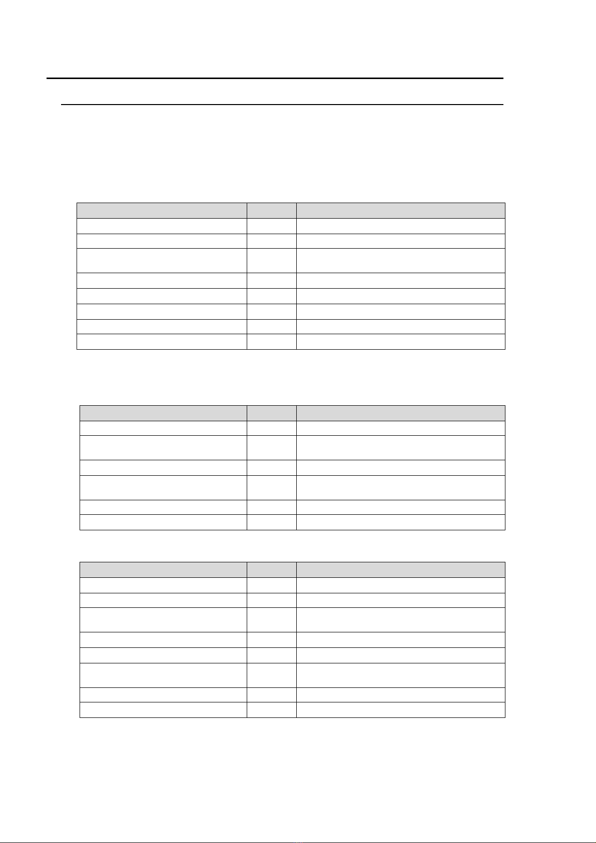
Packing List
ITEM QTY REMARKS
HVS-100ARC 1 Arcnet card
Shielded plate 1 For Arcnet card protection
W-sems screw 4 Used to secure Arcnet Card.
(washer included)
Binding screw (Large) 2 Used to secure the Arcnet connector.
Binding screw (Small) 1 Used to secure the Arcnet connector.
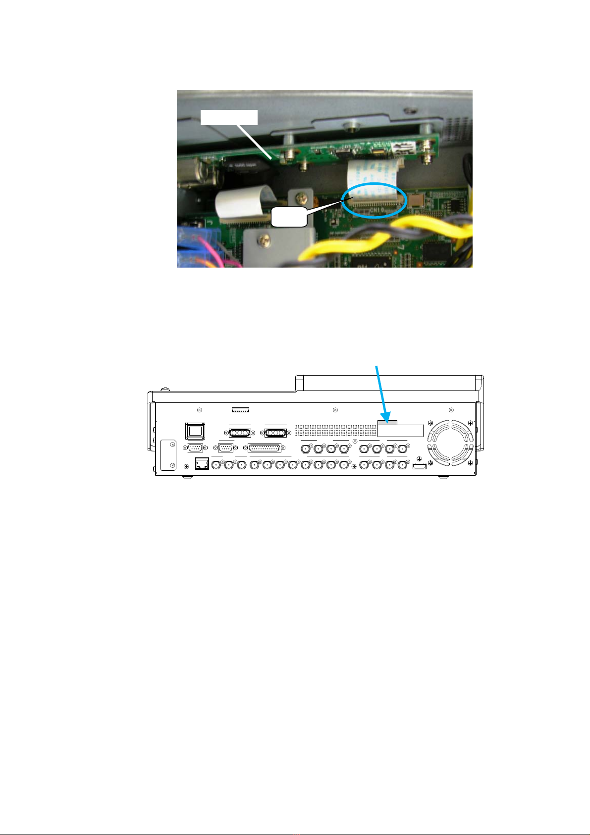
Flex cable 1 Used to connect Arcnet Card to Main Card.
HVS-100ARC rating label 1
Installation Guide 1 This Guide Book
Note that different parts are used for HVS-100 or 110 installation as shown in the tables below.
Parts List used for HVS-100 installation
ITEM QTY REMARKS
HVS-100ARC 1 Arcnet card
W-sems screw 4 Used to secure Arcnet Card.
(washer included)
Binding screw (Small) 1 Used to secure the Arcnet connector.
Flex cable 1 Used to connect the Arcnet Card to the Main
Card.
HVS-100ARC rating label 1
Installation Guide 1 This guide book
Parts List used for HVS-110 installation
ITEM QTY REMARKS
HVS-100ARC 1 Arcnet card
Shielded plate 1 For Arcnet card protection
W-sems screw 4 Used to secure Arcnet Card.
(washer included)
Binding screw (Large) 2 Used to secure the Arcnet connector.
Binding screw (Small) 1 Used to secure the Arcnet connector.
Flex cable 1 Used to connect the Arcnet Card to the Main
Card.
HVS-100ARC rating label 1
Installation Guide 1 This guide book