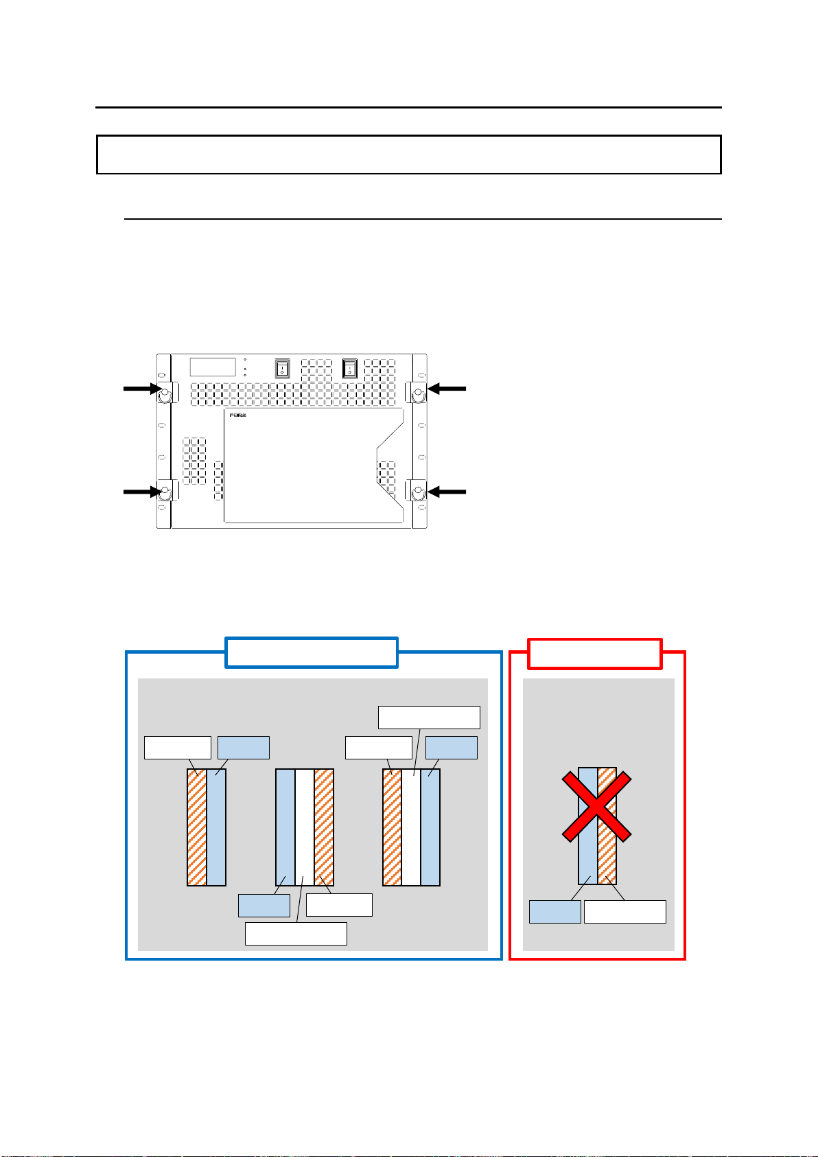
When installing into INPUT1 to 8
(Slot No.1 to 4 and 13 to 16) slots:
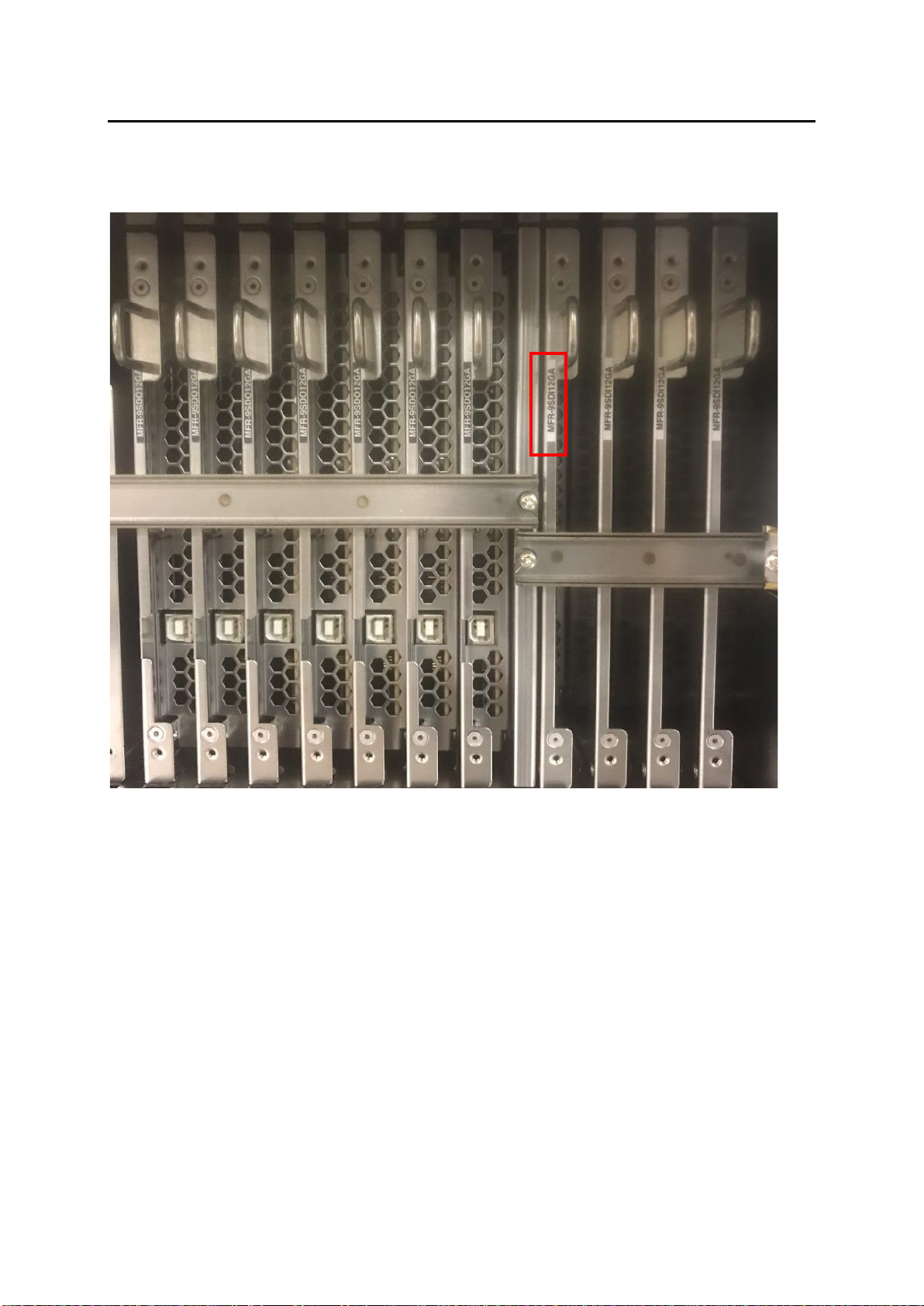
Do not install MFR-9SDI12GA cards just right
(viewed from the rear) of an MFR-9SDI card.
When installing into INPUT9 to 16
(Slot No.17 to 20 and 29 to 32) slots:
Do not install MFR-9SDI12GA cards just left
(viewed from the rear) of an MFR-9SDI card.
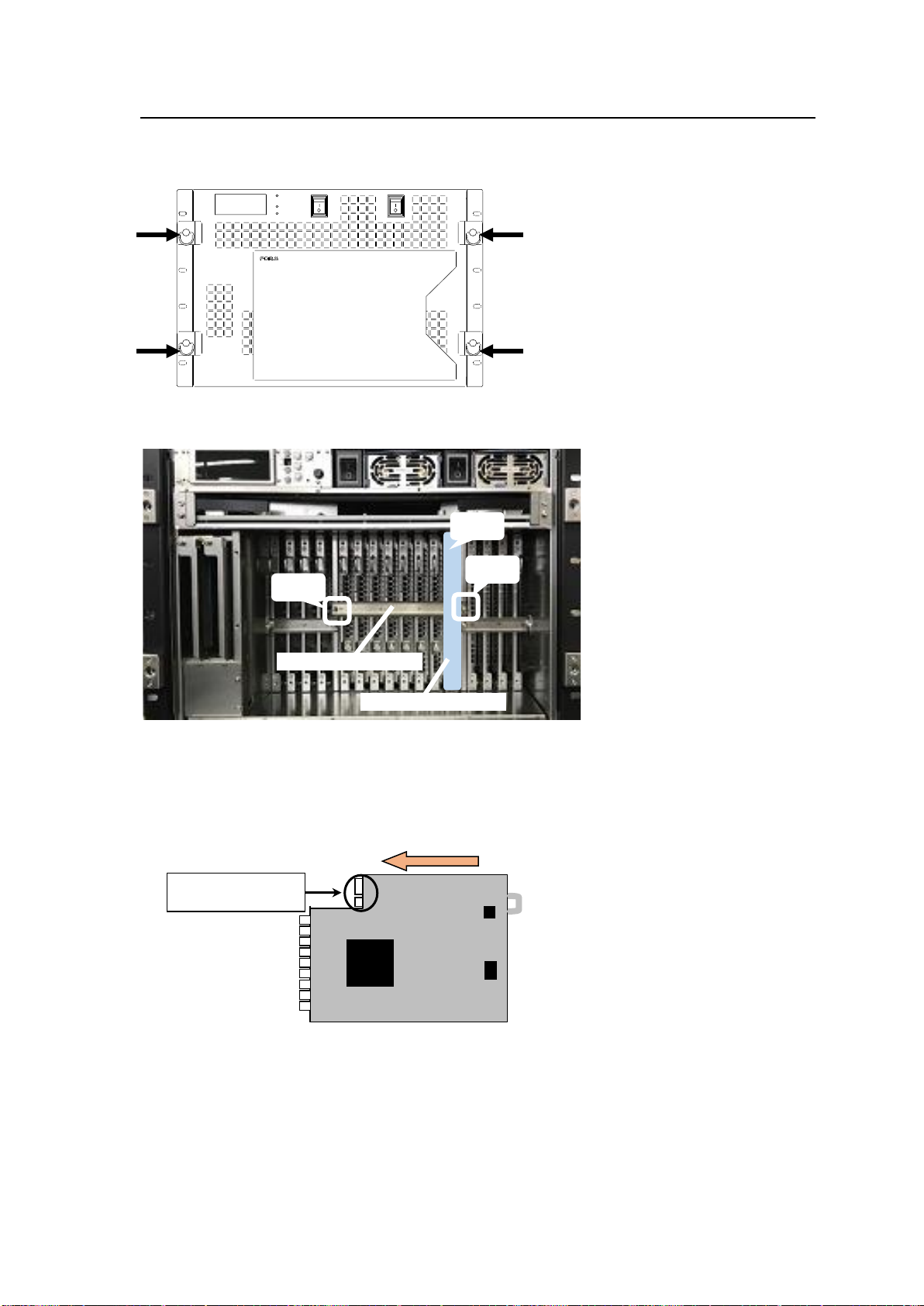
If an MFR-9SDI12GA is installed into a wrong slot,
BNC cables cannot be connected or BNC connectors
or BNC cables may be damaged.
➢See Sec. 3-1. “Checking Installation Slots”
for details.
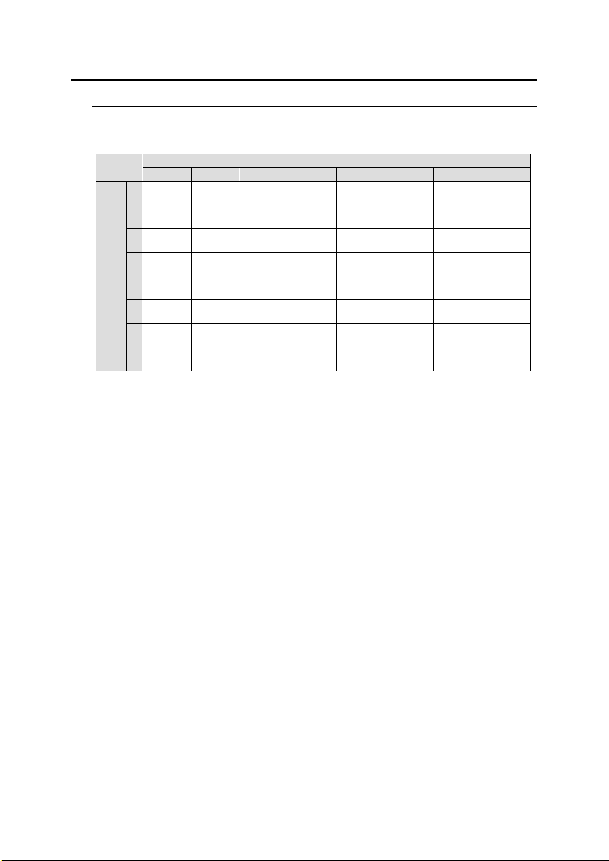
SLOT
INPUT OUTPUT INPUT
910 11 12 910 11 12 13 14 15 16 13 14 15 16
MFR-6100
AC100-240V 50/60Hz IN
AC100-240V 50/60Hz IN
12
INPUT
232C 422
SERIAL
REF IN
ALARM
CPU2
MFR-LAN PC-LAN
FAN 6
CPU1
MFR-LAN PC-LAN
FAN 5
INPUT
1 2 3 4
1
9
8
7
6
5
4
3
2
1 1 1
222
3 3 3
444
5 5 5
6 6 6
777
8 8 8
999
OUTPUT
1 2 3 4 5 6 7 8
1 1 1 1 1 1 1 1
22222222
3 3 3 3 3 3 3 3
44444444
5 5 5 5 5 5 5 5
66666666
7 7 7 7 7 7 7 7
88888888
9 9 9 9 9 9 9 9
INPUT
5 6 7 8
SLOT
INPUT OUTPUT INPUT
1 2 3 4 1 2 3 4 5 6 7 8 5 6 7 8
1 1 1 1
2 2 2 2
3 3 3 3
4 4 4 4
5 5 5 5
6 6 6 6
7 7 7 7
8 8 8 8
9 9 9 9
FAN 1 FAN 2 FAN 3 FAN 4
INPUT OUTPUT
910 11 12 910 11 12 13 14 15 16 13 14 15 16
1 1 1 1
1 1 1 1 1 1 1 1
1 1 1 1
2 2 2 2 2 2 2 2
3333
33333333
3 3 33
4 4 4 4 4 4 4 4 4 4 4 4 4 4 4 4
5555
55555555
5555
6 6 6 6 6 6 6 6 6 6 6 6 6 6 6 6
7777
77777777
7777
8
9
8 8 8 8 8 8 8 8 8 8 8 8 8 8 8
9999
99999999
999