for Living 063-2487-0 User manual

Shower Tension Pole Caddy
Model No. 063-2487-0
Toll-free: 1-800-892-3986
IMPORTANT: Please read this manual carefully before beginning assembly of this product.
Keep this manual for future reference.
Assembly Instructions
IS02161-I2

Imported for Trileaf Distribution Trifeuil Toronto, Canada M4S 2B8

3
Table of ContentsParts List
Table of Contents 3
Parts List 3-4
Assembly 4-11
Cleaning and Maintenance 12
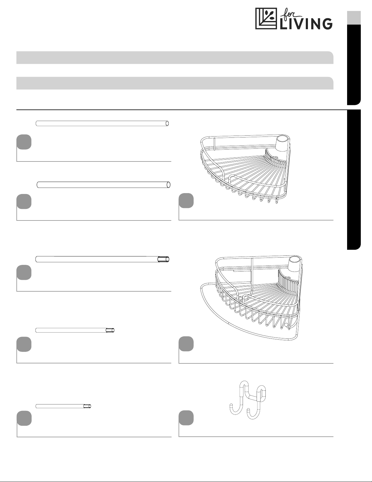
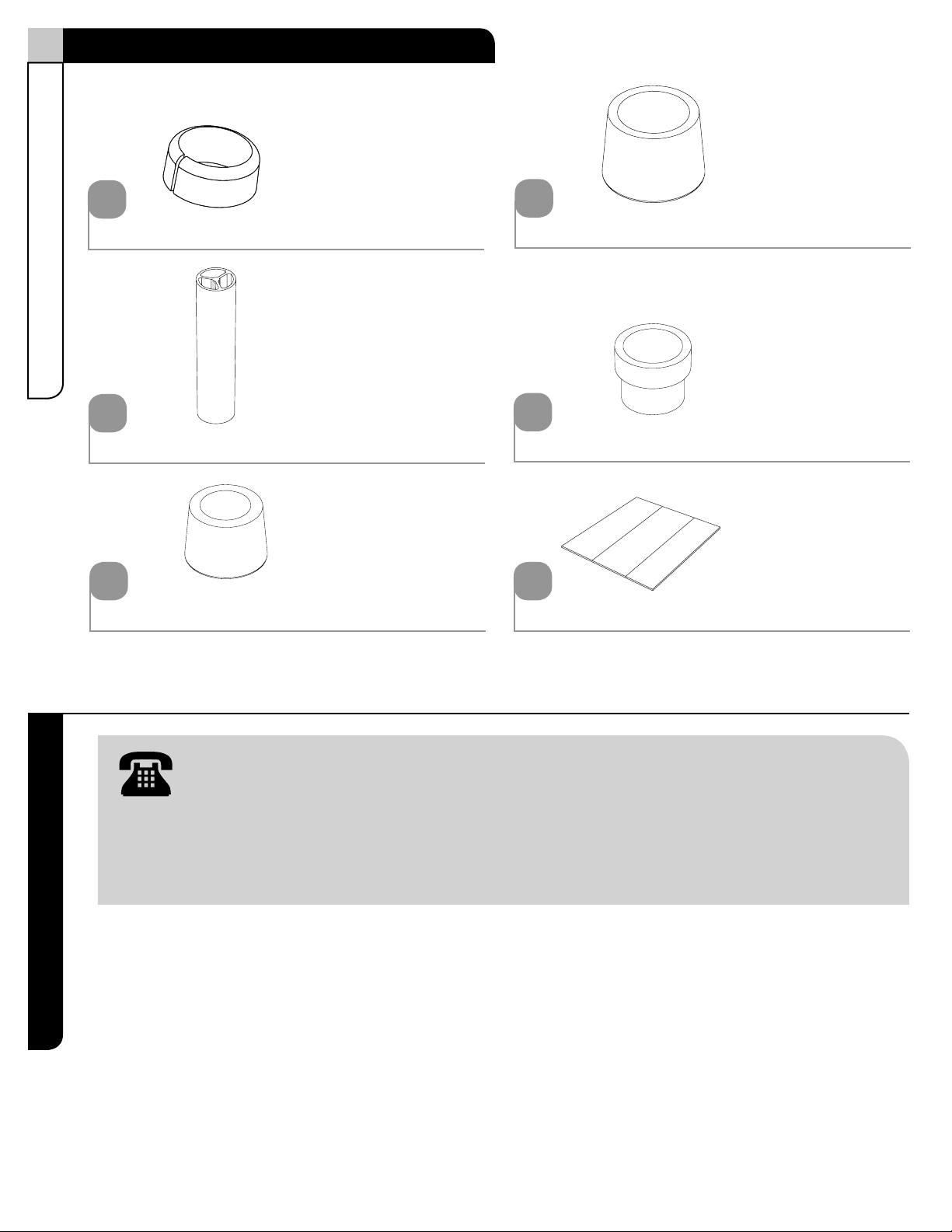
3/4 in. (1.9 cm) tube 1 - 1
Straight tube
(spring packed inside)
2 - 1
Long tapered tube 3 - 1
Medium tapered tube 4 - 1
1
2
3
4
Shelf 6 - 3
6
Shelf with towel bar 7 - 1
7
Short tapered tube 5 - 1
5
Hook 8 - 2
8

Let us help you!
DO NOT RETURN YOUR PRODUCT TO THE STORE. CALL US FIRST!
1-800-892-3986
If you have questions regarding your product, require warranty assistance,
or have damaged or missing parts, please call our customer service toll-free helpline.
Contact us for assistance; we’re here to help.
IMPORTANT: Please read and understand this manual before any assembly. Before beginning assembly of
product, make sure all parts are present. Compare parts with packaging contents list. If any part is missing, or if
you have any questions, contact the service centre at 1-800-892-3986 (toll free).
Place all parts from the box in a cleared area and position them on the floor in front of you. Remove
all packing materials and place them back into the box. Do not dispose of the packing materials
until assembly is complete. Read each step carefully before beginning any assembly and make
sure you understand each step. If you are missing a part, please call our toll-free number for
assistance: 1-800-892-3986.
4Model No. 063-2487-0
Wedges - 4
A
Spacer - 3
B
Small end cap - 1
C
Large end cap - 1
D
Transition ring - 1
E
Tape strip - 2
F
Parts ListAssembly

5
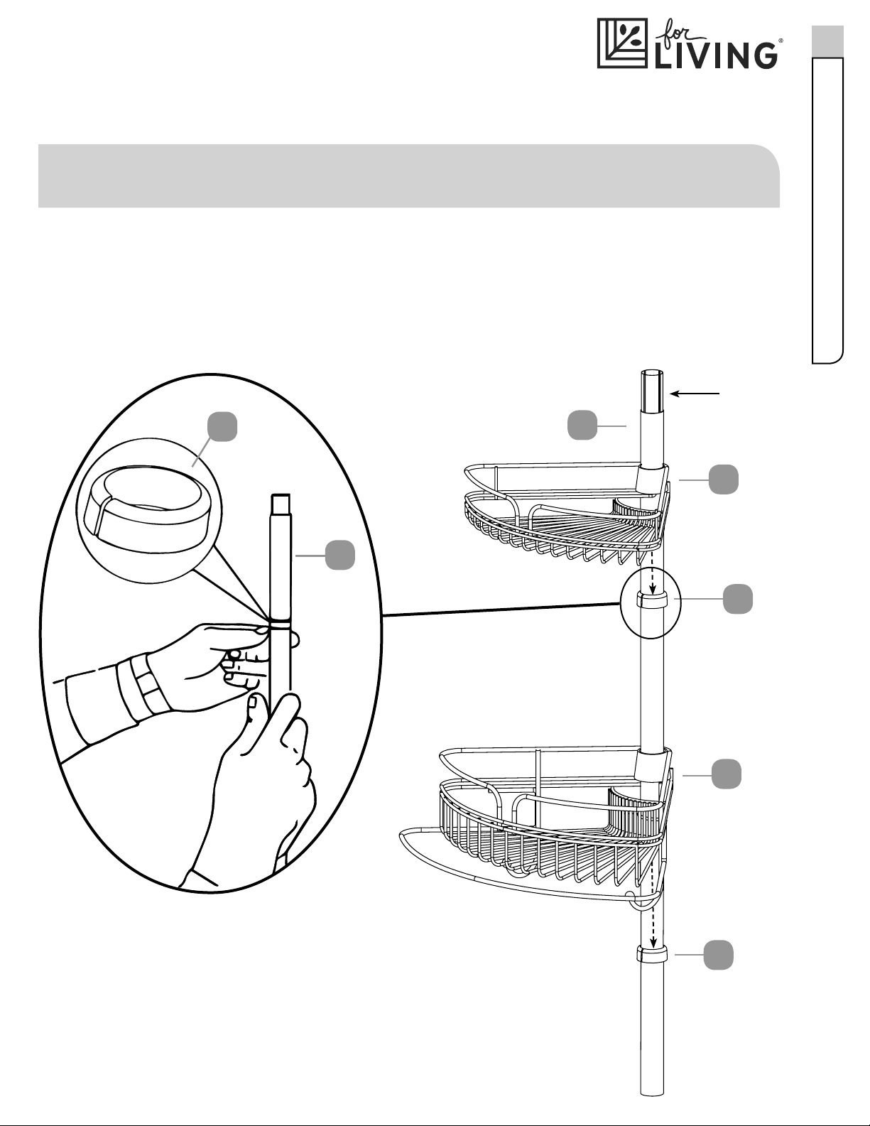
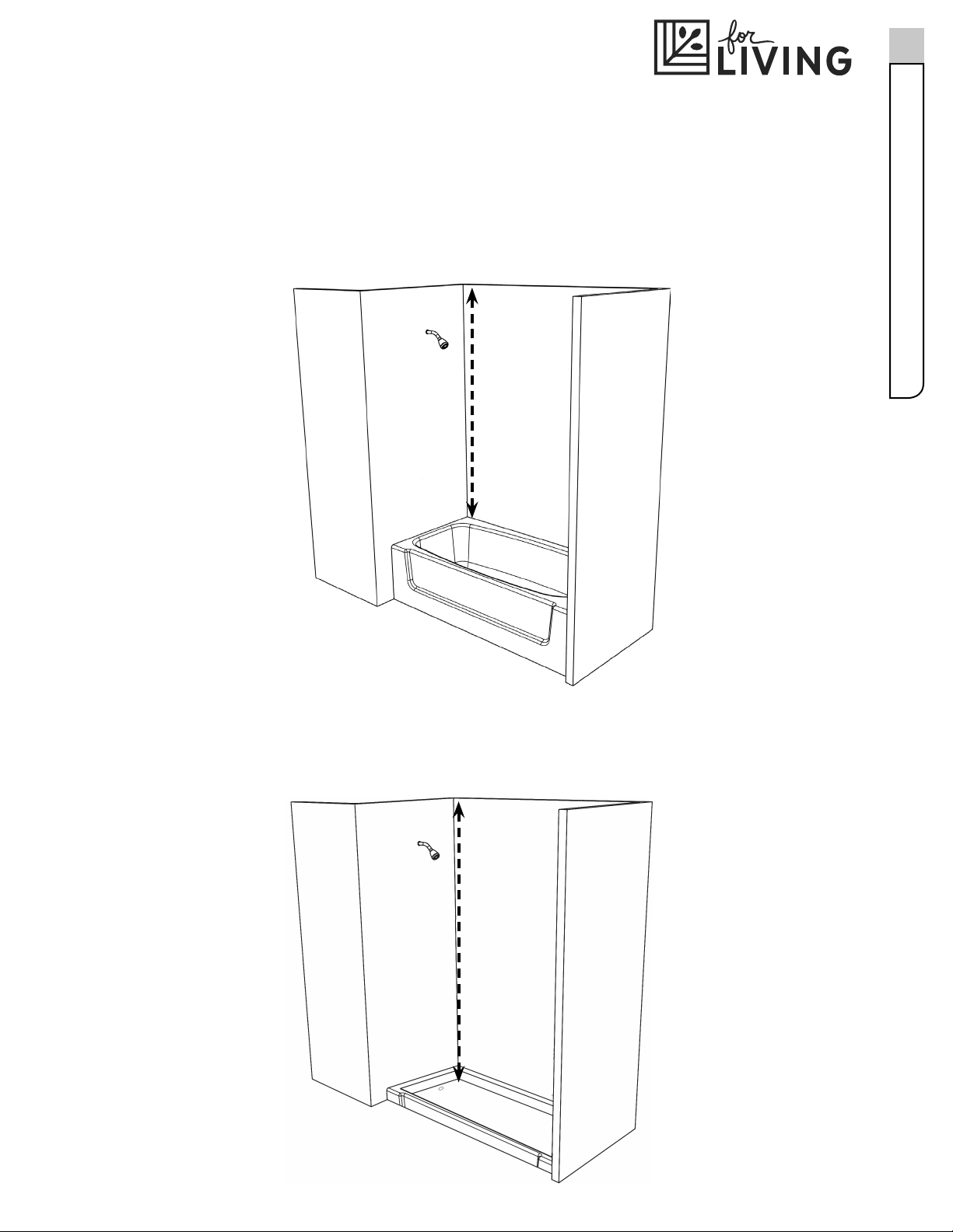
Step 1
Measure the distance between the tub ledge or the shower stall oor to the ceiling to the
nearest half inch.
Fig. 2
shower stall oor
(opening height)
Fig. 1
tub ledge
(opening height)
Assembly

Step 2
See the chart to determine what tubes (3), (4), (5) and spacers (B) are needed.
Opening Height:
Use Tubes:
Number of Spacers (B) Used:
6Model No. 063-2487-0
Assembly
Opening Height
(see g.1, 2 from step 1)
Use Tubes (3), (4), and (5)
as NEEDED
Number of Spacers (B)
Used
60 - 61.5 in. (152.5 - 156 cm) (4) 3
62 - 64 in. (157.5 - 162,5 cm) (3) 2
64.5 - 67 in. (164 - 170 cm) (3) 3
67.5 - 71 in. (171.5 - 180 cm) (3) and (5) 0
71.5 - 73 in. (187 - 190.5 cm) (3) and (5) 1
73.5 - 75 in. (192 - 198 cm) (3) and (4) 0
75.5 - 78 in. (3) and (4) 1
78.5 - 81 in. (199 - 206 cm) (3) and (4) 2
81.5 - 84.5 in. (207 - 215 cm) (3) and (4) 3
85 - 88.5 in. (216 - 225 cm) (3), (4) and (5) 0
89 - 91.5 in. (226 - 232.5 cm) (3), (4) and (5) 1
92 - 95 in. (234 - 241.5 cm) (3), (4) and (5) 2
95.5 - 97 in. (242,5 - 246.5 cm) (3), (4) and (5) 3
NOTE: NO MATTER THE DISTANCE TUBES 1 AND 2 ARE ALWAYS USED.
NOTE: Please write down your measurement and tubes and number of spacers (B) needed below;
you will need them later.
A3
6
7
A
3
A
tapered end
Step 3
Requires 3, 6, 7, A
Place a wedge (A)
(tapered or rounded end up)
on one of the long tapered tubes (3) approximately
half way down.
Slide shelf with towel bar (7) down the tube and t over the wedge (A) and repeat this process for a
shelf (6).
Repeat this step for the medium tapered tube (4) and the other shelves (6).
7
Assembly
NOTE: Assembly shown for 97 in. opening height. The following assembly should be modied
based on your opening height, SEE CHART ON PAGE 6.

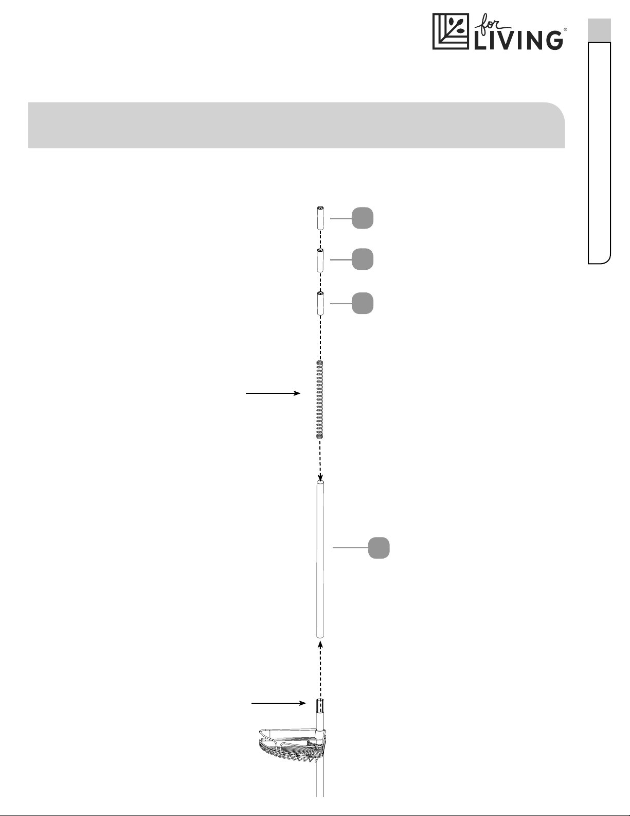
Step 4
Place the tapered end of the long tube (3) into the untapered end of the medium tube (4).
4
3
tapered end
tapered end
D
bottom tube assembly
Step 5
Requires 5, D
Place the large end cap (D) onto the short tapered tube (5).
Place the tapered end of the short tapered tube (5) into the untapered end of the bottom
tube assembly.
5
8Model No. 063-2487-0
Assembly
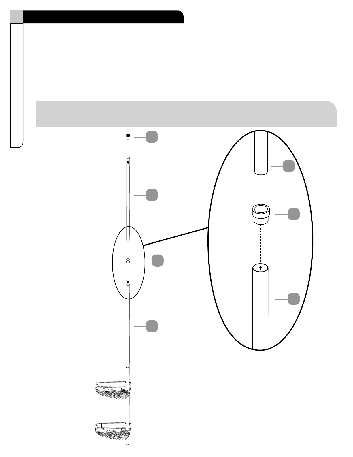
Step 6
Requires 2, B
Place straight tube (2) on top of the assembly.
Insert three spacers (B) into the straight tube (2).
B
B
B
2
spring is packed inside
straight tube (2)
tapered end
9
Assembly
NOTE: Assembly shown for 97 in. opening height. The following assembly should be modied
based on your opening height, SEE CHART ON PAGE 6.
Step 7
Requires 1, C, E, F
Place the small end cap (C) onto the 3/4 in. tube (1).
Insert the transition ring (E) into the straight tube (2).
Slide the 3/4 in. tube (1) through the transition ring (E) and into the straight tube (2).
Place the tape strips (F) around the seams of the tubes.
2
1
C
2
E
1
E
10 Model No. 063-2487-0
Assembly
NOTE: After inserting the 3/4 in. tube (1) into the straight tube (2) ensure that the transition ring (E)
ts snuggly over the straight tube (2).

11
Step 8
Compress top of the unit against the ceiling in the desired location.
Move the bottom end into place so that the unit is in a vertical position.
Attach hooks (8) in the desired location on a shelf (6 or 7).
NOTE: Make sure you are installing in a clean, dry and safe environment.
Fig. 2
shower stall oor
(opening height)
Fig. 1
tub ledge
(opening height)
NOTE: THE MANUFACTURER SHALL NOT BE LIABLE FOR ANY SPECIAL,
INCIDENTAL, AND/OR CONSEQUENTIAL DAMAGES.
Assembly

12 Model No. 063-2487-0
Cleaning and Maintenance
• Cleaning with a dry cloth may be sucient.
• For other stains or marks, wipe gently with a damp cloth.
• Do not use strong detergents or abrasive cleaners; they may damage the surface of this product.

Imported for Trileaf Distribution Trifeuil Toronto, Canada M4S 2B8
IS02161-I2

Support sur montant à tension
pour douche
Nº de modèle : 063-2487-0
Numéro sans frais : 1 800 892-3986
IMPORTANT : Veuillez lire attentivement ce guide avant de procéder à l’assemblage de cet article.
Conservez ce guide aux ns de consultation ultérieure.
Consignes d’assemblage
IS02161-I2
MD

Importé pour Trileaf Distribution Trifeuil Toronto, Canada M4S 2B8
3
MD
Table des matièresListe des pièces
Table des matières 3
Liste des pièces 3-4
Assemblage 4-11
Nettoyage et entretien 12
Tube de 3/4 po 1 - 1
Tube droit
(ressort interne)
2 - 1
Long tube à extrémité conique 3 - 1
Tube moyen à extrémité conique 4 - 1
1
2
3
4
Tablette 6 - 3
6
Tablette avec barre de serviette 7 - 1
7
Tube court à extrémité conique 5 - 1
5
Crochet 8 - 2
8
Laissez-nous vous aider!
NE RETOURNEZ PAS VOTRE ARTICLE AU MAGASIN. APPELEZ-NOUS D'ABORD!
1 800 892-3986
If you have questions regarding your product, require warranty assistance,
or have damaged or missing parts, please call our customer service toll-free helpline.
Contact us for assistance; we’re here to help.
IMPORTANT : Veuillez lire et bien comprendre ce guide avant de procéder à l’assemblage. Avant de procéder
à l’assemblage du produit, assurez-vous que toutes les pièces sont présentes. Comparez les pièces à la liste de
contenu de l’emballage. S’il manque des pièces, ou si vous avez des questions, communiquez avec le service
d’assistance téléphonique sans frais en composant le 1 800 892-3986 (numéro de sans frais).
Mettez toutes les pièces de la boîte dans une zone dégagée et positionnez-les sur le sol devant vous.
Retirez tout le matériel d’emballage et remettez-le dans la boîte. Ne le jetez pas avant d’avoir terminé
l’assemblage. Veuillez lire attentivement chaque étape avant de procéder à l’assemblage, et assurez-
vous de comprendre toutes les étapes. S'il vous manque une pièce, veuillez composer notre numéro
d'assistance sans frais au 1 800 892-3986.
4Nº de modèle : 063-2487-0
Cales - 4
A
Entretoise - 3
B
Petit embout - 1
C
Gros embout - 1
D
Anneau de transition - 1
E
Ruban adhésif - 2
F
Liste des piècesAssemblage
5
MD
Étape 1
Mesurez la distance entre le rebord de la baignoire ou le sol de la cabine de douche et le plafond au
demi-pouce près.
Fig. 2
sol de la cabine de douche
(hauteur d’ouverture)
Fig. 1
rebord de la baignoire
(hauteur d’ouverture)
Assemblage

Étape 2
Consultez le tableau pour déterminer quels tubes (3), (4), (5) et entretoises (B) sont nécessaires.
Hauteur d'ouverture :
Tubes à utiliser :
Nombre d’entretoises (B) à utiliser :
6Nº de modèle : 063-2487-0
Assemblage
Hauteur d'ouverture
(voir gures 1, 2 à l'étape 1)
Utilisez les tubes (3), (4) et (5)
AU BESOIN Nombre d’entretoises (B)
utilisées
60 - 61,5 po (152,5 - 156 cm) (4) 3
62 - 64 po (157,5 - 162,5 cm) (3) 2
64,5 - 67 po (164 - 170 cm) (3) 3
67,5 - 71 po (171,5 - 180 cm) (3) et (5) 0
71,5 - 73 po (181,5 - 185,5 cm) (3) et (5) 1
73,5 - 75 po (187 - 190,5 cm) (3) et (4) 0
75,5 - 78 po (192 - 198 cm) (3) et (4) 1
78,5 - 81 po (199 - 206 cm) (3) et (4) 2
81,5 - 84,5 po (207 - 215 cm) (3) et (4) 3
85 - 88,5 po (216 - 225 cm) (3), (4) et (5) 0
89 - 91,5 po (226 - 232,5 cm) (3), (4) et (5) 1
92 - 95 po (234 - 241,5 cm) (3), (4) et (5) 2
95,5 - 97 po (242,5 - 246,5 cm) (3), (4) et (5) 3
REMARQUE : LES TUBES 1 ET 2 SONT TOUJOURS UTILISÉS, PEU IMPORTE LA DISTANCE.
REMARQUE : Veuillez inscrire votre mesure, le nombre de tubes et le nombre d’entretoises (B)
nécessaires ci-dessous; vous en aurez besoin plus tard.

A3
6
7
A
3
A
extrémité conique
Étape 3
Pièces requises : 3, 6, 7, A
Placez une cale (A) (avec l'extrémité conique ou arrondie vers le haut) sur l’un des longs tubes à
extrémité conique (3) environ à mi-course.
Glissez la tablette avec porte-serviettes (7) sur le tube et placez-la sur la cale (A). Répétez cette procédure
pour une tablette (6).
Répétez cette étape pour les tubes moyens à extrémité conique (4) et les autres tablettes (6).
7
MD
Assemblage
REMARQUE : Assemblage indiqué pour une ouverture de 97 po. L’assemblage suivant doit être
modié en fonction de la hauteur d’ouverture, CONSULTEZ LE TABLEAU À LA PAGE 6.
Table of contents
Languages:
Other for Living Bathroom Fixture manuals


Popular Bathroom Fixture manuals by other brands

Kohler
Kohler Mira Sport Max J03G Installation and user guide

Moen
Moen 186117 Series installation guide

Hans Grohe
Hans Grohe Raindance Showerpipe 27235000 Instructions for use/assembly instructions

Signature Hardware
Signature Hardware ROUND SWIVEL BODY SPRAY 948942 Install

fine fixtures
fine fixtures AC3TH installation manual

LIXIL
LIXIL HP50 Series quick start guide


