for Living 063-6294-4 User manual
Shower Tension Pole Caddy
Model No. 063-6294-4
Toll-free: 1-800-892-3986
IMPORTANT: Please read this manual carefully before beginning assembly of this product.
Keep this manual for future reference.
Assembly Instructions
IS02157-I2

Imported for Trileaf Distribution Trifeuil Toronto, Canada M4S 2B8
3
Table of ContentsParts List
Table of Contents 3
Parts List 3
Assembly 4-14
Cleaning and Maintenance 15
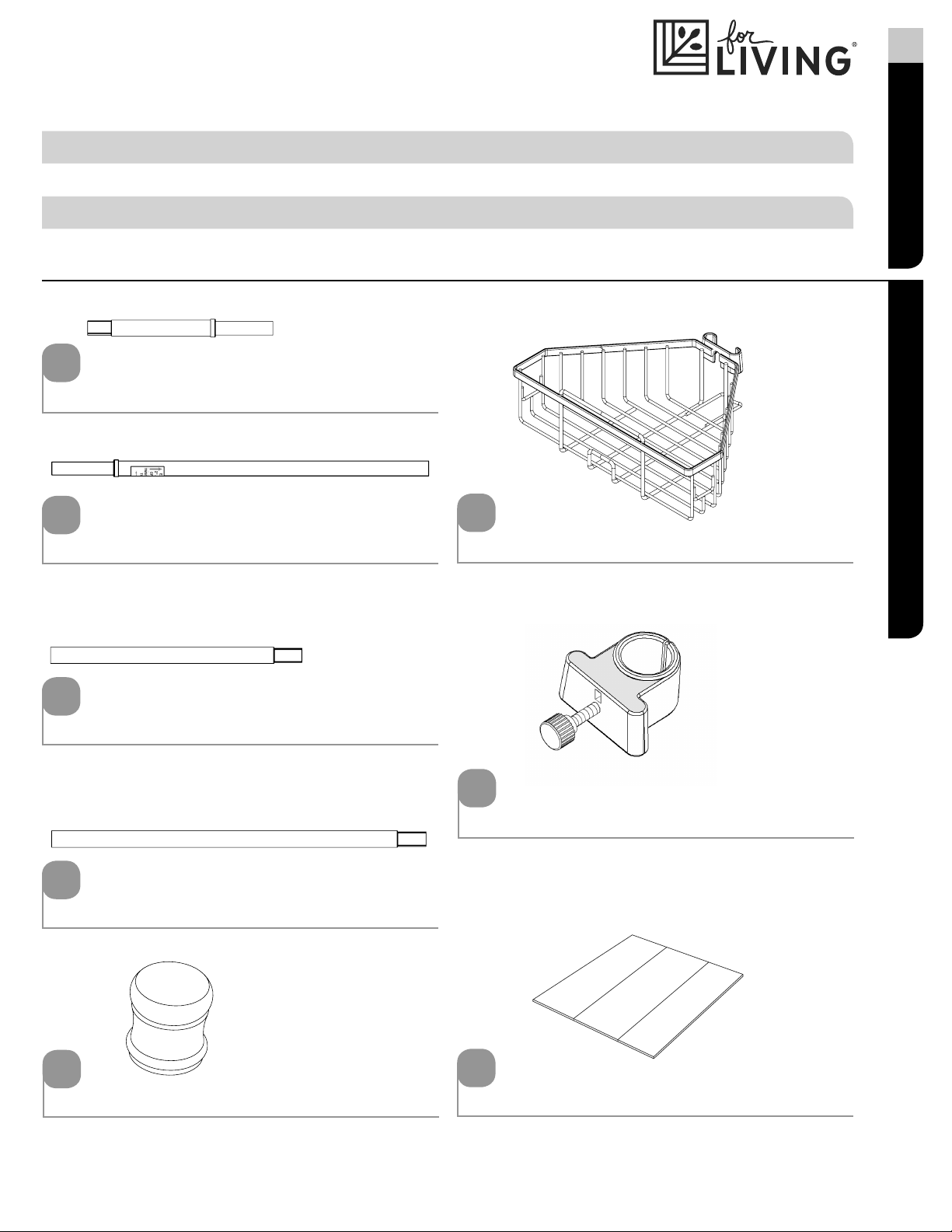
Spring tube set 1 - 1
Twist tube 2 - 1
Medium tapered tube 3 - 2
Long tapered tube 4 - 2
1
2
3
4
Shelf 6 - 4
6
Tube collar 7 - 4
7
End cap 5 - 2
5
Tape strip 8 - 2
8

Let us help you!
DO NOT RETURN YOUR PRODUCT TO THE STORE. CALL US FIRST!
1-800-892-3986
If you have questions regarding your product, require warranty assistance,
or have damaged or missing parts, please call our customer service toll-free helpline.
Contact us for assistance; we’re here to help.
IMPORTANT: Please read and understand this manual before any assembly. Before beginning assembly of
product, make sure all parts are present. Compare parts with packaging contents list. If any part is missing, or if
you have any questions, contact the service centre at 1-800-892-3986 (toll free).
Place all parts from the box in a cleared area and position them on the floor in front of you. Remove
all packing materials and place them back into the box. Do not dispose of the packing materials
until assembly is complete. Read each step carefully before beginning any assembly and make
sure you understand each step. If you are missing a part, please call our toll-free number for
assistance: 1-800-892-3986.
4Model No. 063-6294-4
Assembly
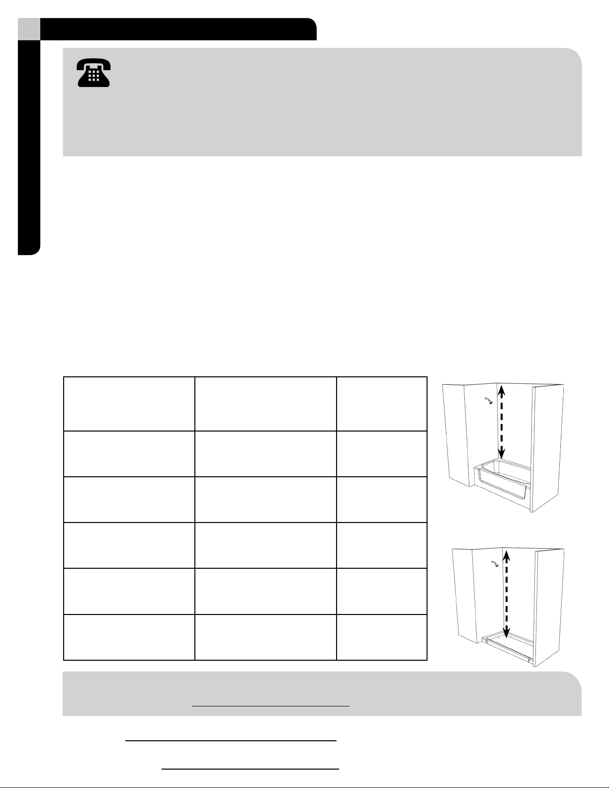
Step 1
Measure the distance between the tub ledge or the shower stall oor to the ceiling to the nearest inch.
Use the chart to determine what tubes are needed; tube bags are labeled.
Fig. 2
shower stall oor distance
Fig. 1
tub ledge distance
Distance:
Use Tubes:
NOTE: Please write down your measurement and tubes and number of spacers (F) needed below;
you will need them later.
Distance
(see g. 1, 2)
Tubes Used Turn to
Page Number
60 - 66 in.
(152.4 - 167.6 cm) (1), (2) and (4) page 5
67 - 76 in.
(170.2 - 193 cm) (1), (2) (3) and (4) page 6
77 - 84 in.
(195.6 - 213.4 cm) (1), (2) (4) and (4) page 7
85 - 96 in.
(215.9 - 243.8 cm) (1), (2) (3), (4) and (4) page 8
97 - 108 in.
(246.4 - 274.3 cm) (1), (2) (3), (3), (4) and (4) page 9

tapered end
7
7
7
7
4
set screw
4
top
7
5
5
Fig. 2
shower stall oor distance
Assembly
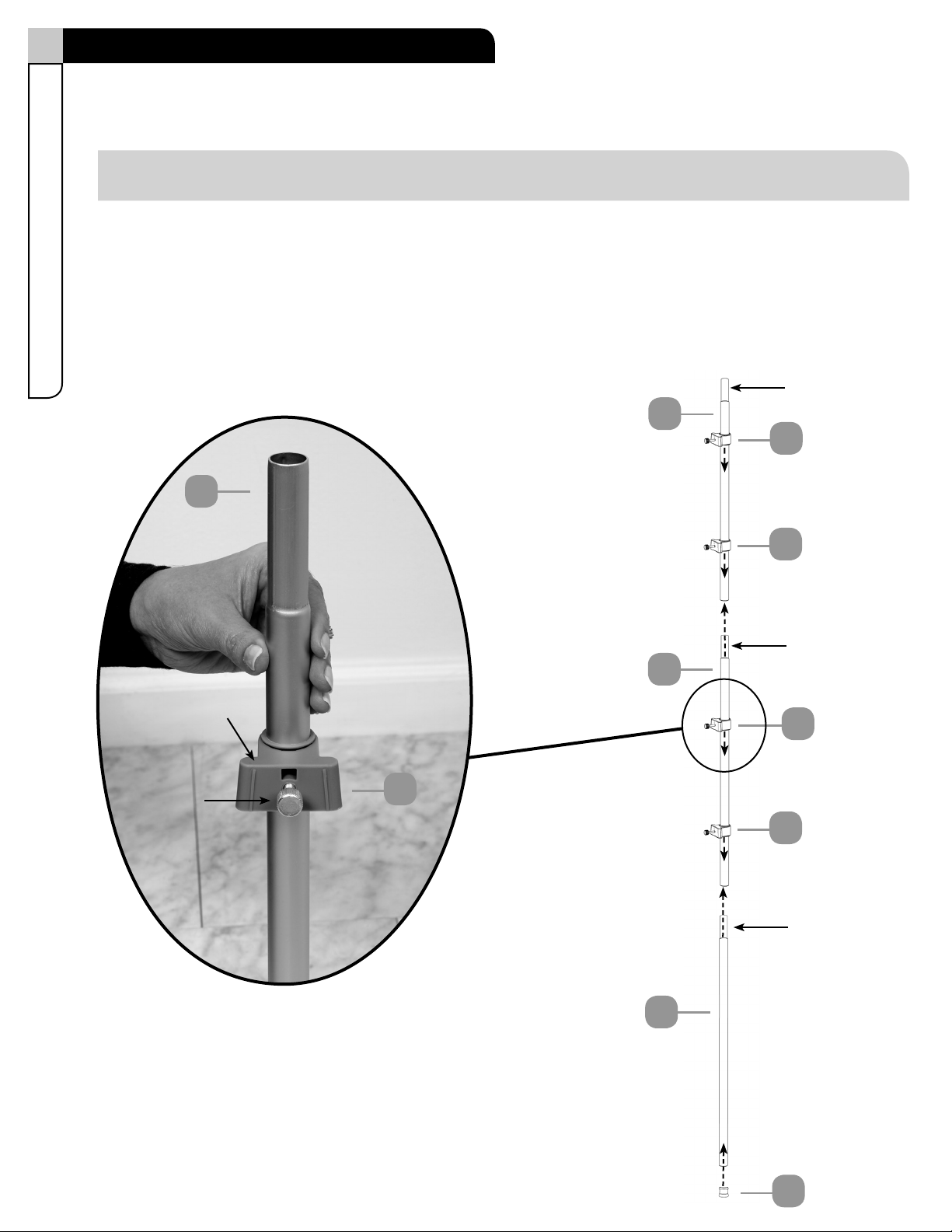
Step 2
Requires 4, 5, 7
Slide all four tube collars (7) down a long tapered tube (4) and use set screws to loosely tighten into
place; you will be adjusting later.
Place an end cap (5) onto the long tapered tube (4). This is the tube assembly.
Now continue to step 3, page 10.
NOTE: Assembly shown for 60 - 66 in. distance.

6Model No. 063-6294-4
Assembly
tapered end
7
7
7
7
3
set screw
4
top
7
Step 2
Requires 3, 4, 5, 7
Slide two tube collars (7) down a long tapered tube (D) and use set screws to loosely tighten into
place; you will be adjusting later. Repeat process for ONE medium tapered tube (3).
Place an end cap (5) onto the long tapered tube (4).
Place the tapered end of the long tube (4) into the untapered end of the medium tube (3). This is the
tube assembly.
Now continue to step 3, page 10.
NOTE: Assembly shown for 67 - 76 in. distance.
5
4
tapered end

7
Assembly
tapered end
7
7
7
7
4
set screw
4
top
7
Step 2
Requires 4, 4, 5, 7
Slide two tube collars (7) down a long tapered tube (4) and use set screws to loosely tighten into
place; you will be adjusting later. Repeat process for the other long tapered tube (4).
Place an end cap (5) onto the long tapered tube (4).
Place the tapered end of the long tube (4) into the untapered end of the other long tube (4). This is the
tube assembly.
Now continue to step 3, page 10.
NOTE: Assembly shown for 77 - 84 in. distance.
5
4
tapered end
tapered end
7
7
7
7
4
set screw
4
top
7
Step 2
Requires 3, 4, 5, 7
Slide two tube collars (7) down a long tapered tube (4) and use set screws to loosely tighten into
place; you will be adjusting later. Repeat process for the medium tapered tube (3).
Place the tapered end of the long tapered tube (4) into the untapered end of the medium tapered
tube (3).
Place an end cap (5) onto the other long tapered tube (4) and then place the tapered end into the other
long tapered tube (4). This is the tube assembly.
Now continue to step 3, page 10.
NOTE: Assembly shown for 85 - 96 in. distance.
5
tapered end
4
tapered end
3
8Model No. 063-6294-4
Assembly

tapered end
7
7
7
4
set screw
3
top
7
Step 2
Requires 3, 3, 4, 4, 5, 7
Slide two tube collars (7) down a medium tapered tube (5) and use set screws to loosely tighten into
place, you will be adjusting later. Repeat process for the medium tapered tube (3).
Place an end cap (5) onto the other long tapered tube (4).
Place the tapered end of the long tapered tube (4) with end cap (5) into the untapered end of the other
long tapered tube (4), then repeat for the two medium tapered tubes (3). This is the tube assembly.
Now continue to step 3, page 10.
NOTE: Assembly shown for 97 - 108 in. distance.
5
tapered end
4
tapered end
3
3
7
tapered end
9
Assembly
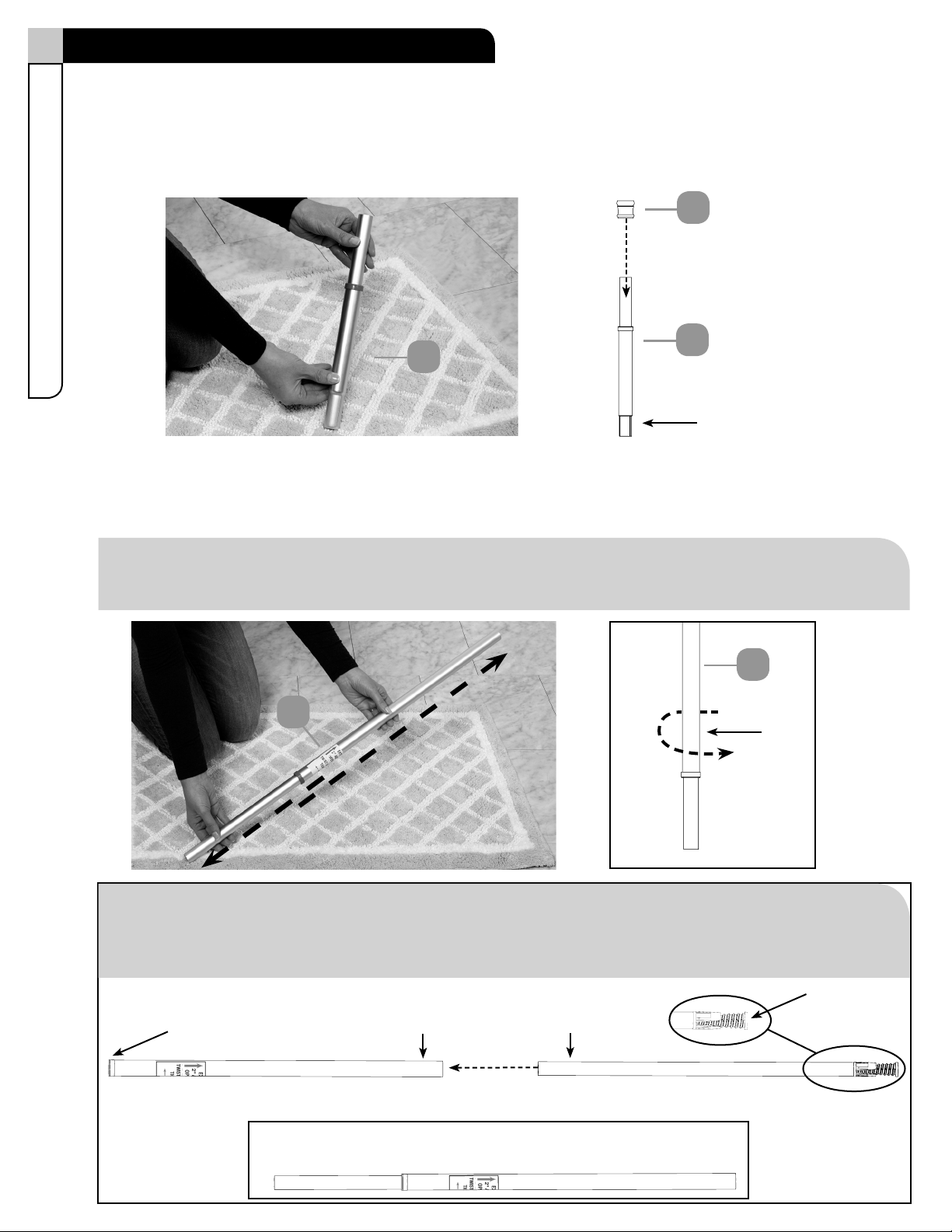
Step 3
Requires 1, 5
Place the other end cap (5) onto the spring tube set (1). NOTE: Assemble on the oor.
1
5
tapered end
1
Step 4
Requires 2
Check that the twist tube (2) can easily slide up and down. NOTE: Assemble on the oor.
2
loosen
2
correct assembly of twist tube (2)
INNER tube
OUTER tube
transition ring
plastic spiral
10 Model No. 063-6294-4
NOTE: If tubes separate, reinsert the inner tube into the outer tube with the plastic spiral opposite
the transition ring. Slide the inner tube until it extends more than halfway out past the transition
ring, as shown below.
Assembly
NOTE: If needed, loosen the twist tube (2) by twisting the OUTER tube COUNTER-CLOCKWISE;
be sure the white plastic spiral is covered by the outer tube.

1
2
tapered end
INNER tube
OUTER tube
11
Step 5
Requires 1, 2
Place the tapered end of the spring tube set (1) into the twist tube (2). NOTE: Assemble on the oor.
Assembly
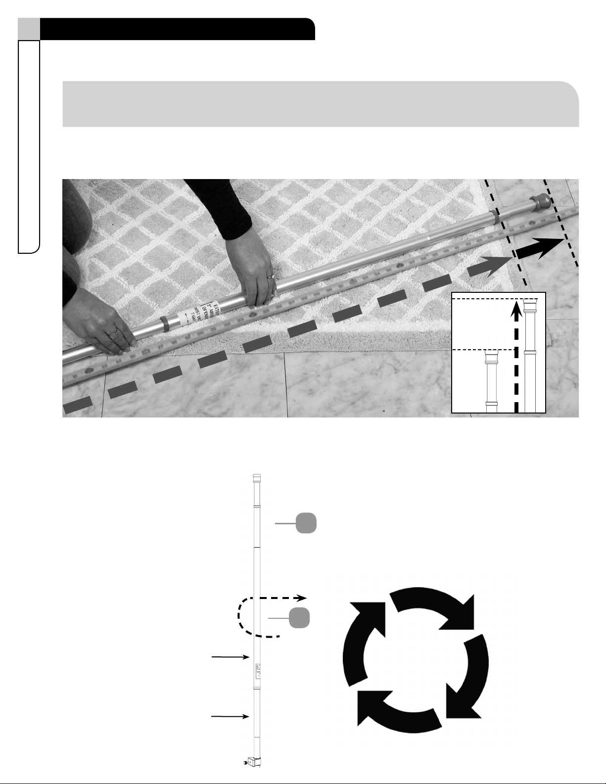
Step 6
Extend the OUTER tube of the twist tube (B) so the assembly measures 2 inches longer than your tub
or shower stall opening height. Refer to your distance on page 3.
1
EXTEND
2 in. longer
EXTEND
2 in. longer
Hold the INNER tube with your right hand and twist the OUTER tube CLOCKWISE (away from you) with
your left hand until tight. NOTE: Assemble on the oor.
INNER tube
OUTER tube
2
twist OUTER tube
CLOCKWISE
until tight
12 Model No. 063-6294-4
Assembly
NOTE: Critical to extend twist tube (B) 2 inches.

Fig. 1
Fig. 2
shower stall oor installation
Fig. 2
tub ledge installation
13
Assembly
Step 7
Requires 8
Place the tape strips (8) around the seams of the tubes.
Place the top of the unit against the ceiling in the desired location (g.1) and then compress the unit
up and move the bottom end into place (g.2) so that the unit is in a vertical position.
NOTE: Make sure you are installing in a clean, dry and safe environment.
NOTE: Make sure the assembly is in place, secure and vertical.
NOTE: If needed, refer to STEP 7 to ensure that the assembly measures 2 inches longer than
your tub or shower stall opening height and that the twist tube (2) is tight.
This ensures the proper tension.
7
7
7
7
6
6
6
6
6
7
14 Model No. 063-6294-4
Assembly
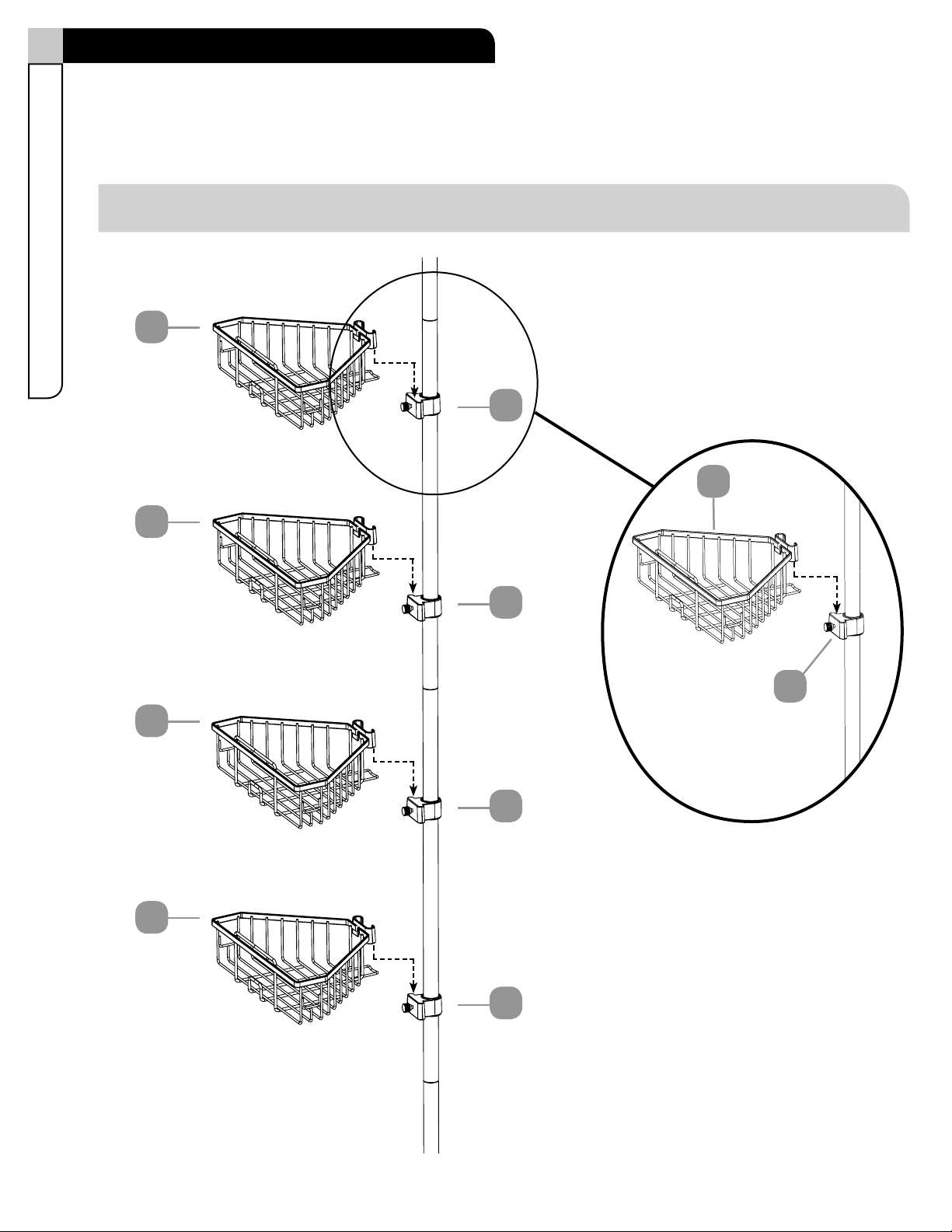
Step 8
Requires 6
Slide shelves (6) onto tube collars (7).
NOTE: Shelves can be adjusted by loosening set screws and moving the tube collars (7) up or down.

15
• Cleaning with a dry cloth may be sucient.
• For other stains or marks, wipe gently with a damp cloth.
• Do not use strong detergents or abrasive cleaners; they may damage the surface of this product.
Cleaning and Maintenance

Imported for Trileaf Distribution Trifeuil Toronto, Canada M4S 2B8
IS02157-I2
Support sur montant à
tension pour douche
Nº de modèle : 063-6294-4
Numéro sans frais : 1 800 892-3986
IMPORTANT : Veuillez lire attentivement ce guide avant de procéder à l’assemblage de cet article.
Conservez ce guide aux ns de consultation ultérieure.
Consignes d’assemblage
IS02157-I2
MD

Importé pour Trileaf Distribution Trifeuil Toronto, Canada M4S 2B8

3
MD
Table des matièresListe des pièces
Table des matières 3
Liste des pièces 3
Assemblage 4-14
Nettoyage et entretien 15
Tube à ressort 1 - 1
Tube de serrage 2 - 1
Tube moyen à extrémité conique 3 - 2
Long tube à extrémité conique 4 - 2
1
2
3
4
Tablette 6 - 4
6
Collier à tube 7 - 4
7
Embout 5 - 2
5
Ruban adhésif 8 - 2
8
Laissez-nous vous aider!
NE RETOURNEZ PAS VOTRE ARTICLE AU MAGASIN. APPELEZ-NOUS D'ABORD!
1 800 892-3986
Si vous avez des questions concernant votre produit, des questions de garantie, ou
avez des pièces endommagées ou manquantes, communiquez avec notre service à
la clientèle en composant le numéro sans frais. Communiquez avec nous si vous avez
besoin d’assistance, nous sommes là pour vous aider.
IMPORTANT : Veuillez lire et bien comprendre ce guide avant de procéder à l’assemblage. Avant de procéder
à l’assemblage du produit, assurez-vous que toutes les pièces sont présentes. Comparez les pièces à la liste de
contenu de l’emballage. S’il manque des pièces, ou si vous avez des questions, communiquez avec le service
d’assistance téléphonique sans frais en composant le 1 800 892-3986 (numéro de sans frais).
Mettez toutes les pièces de la boîte dans une zone dégagée et positionnez-les sur le sol devant vous.
Retirez tout le matériel d'emballage et remettez-le dans la boîte. Ne le jetez pas avant d’avoir terminé
l’assemblage. Veuillez lire attentivement chaque étape avant de procéder à l'assemblage, et assurez-
vous de comprendre toutes les étapes. S'il vous manque une pièce, veuillez composer notre numéro
d'assistance sans frais au 1 800 892-3986.
4Nº de modèle : 063-6294-4
Assemblage
Étape 1
Mesurez la distance entre le rebord de la baignoire ou le sol de la cabine de douche et le plafond au
pouce près.
Consultez le tableau pour déterminer quels tubes sont nécessaires; les sacs
de tubes sont étiquetés.
Fig. 2
douche distance au sol
Fig. 1
distance rebord de la baignoire
Distance :
Tubes à utiliser :
REMARQUE : Veuillez inscrire votre mesure, le nombre de tubes et le nombre d’entretoises (F)
nécessaires ci-dessous; vous en aurez besoin plus tard.
Distance
(voir g. 1, 2)
Tubes utilisés Reportez-vous
à la page
60 - 66 po
(152,4 - 167,6 cm) (1), (2) et (4) page 5
67 - 76 po
(170,2 - 193 cm) (1), (2) (3) et (4) page 6
77 - 84 po
(195,6 - 213,4 cm) (1), (2) (4) et (4) page 7
85 - 96 po
(215,9 - 243,8 cm) (1), (2) (3), (4) et (4) page 8
97 - 108 po
(246,4 - 274,3 cm) (1), (2) (3), (3), (4) et (4) page 9
Table of contents
Languages:
Other for Living Bathroom Fixture manuals


Popular Bathroom Fixture manuals by other brands


Glacier bay
Glacier bay 35603HBHD Use and care guide

Englefield
Englefield STUDIO 5624A installation instructions

Jacuzzi
Jacuzzi Chelsea Installation, use and maintenance

KWC
KWC EXOS675X Installation and operating instructions

DURAVIT
DURAVIT D-Neo Mounting instructions

Symmons
Symmons Duro 0630-DPTP installation guide