foras 5FES 50HZ Technical manual

DV/DM/DC/DTR
®
Use and installation instruction manual
CLOSE-COUPLED 5"PUMPS
5FES 50HZ

[D-CE]
2006/42/CE; 2006/95/CE; 2004/108/CE; 2000/14/CE (followed procedure: annex V);
87/404/CE: 97/23/CE (Cat.1, Mod.A).
[N-A]
EN 60034…; EN 60204-1; EN 60335-1; EN 60335-2-41; EN 61000; EN 55014; EN ISO
12100-1; EN ISO 12100-2; EN ISO 14121-1; EN ISO 3744
Manufacturer and depositary of tecnical documentation:
PENTAX S.p.A.
Viale dell’Industria, 1
37040 Veronella (VR) - Italy
Gianluigi Pedrollo (President)
Veronella (VR), 01/06/2011
Tel. +39 0442 489500 - Fax +39 0442 489510 - www.pentax-pumps.com - E-mail: com@pentax-pumps.it
Sede amministrativa e stabilimento: Viale dell’Industria, 1 - 37040 Veronella (VR) Italy
Manufacturer and depositary of tecnical documentation:
PENTAX S.p.A.
Viale dell’Industria, 1
37040 Veronella (VR) - Italy
Gianluigi Pedrollo (President)
Veronella (VR), 01/06/2011
Gianluigi Pedrollo
DICHIARAZIONE DI CONFORMITÀ
Si dichiara che i prodotti sono conformi
alle prescrizioni delle direttive [D-CE] e
costruiti nel rispetto delle norme
armonizzate [N-A].
DECLARATION OF CONFORMITY
The listed products comply with the
requirements of the Directives [D-CE] and
are built in accordance with the updated,
current regulations [N-A].
CLOSE-COUPLED 5" PUMPS
Use and installation instruction manual ENGLISH
- EN -
During installation, maintenance and use of the
appliance, carefully follow the instructions
provided in the manual. Carefully read the
instruction manual in all its parts before carrying
out any operation on the pump.
In the case of appliances without a plug, a means
of disconnecting the power supply, with omni-
polar contact separation that fully disconnects
under overvoltage category III, must be installed in
the power supply system according to the current
installation rules.
This equipment is not intended to be used by
persons (including children) with reduced physical,
sensoryor mentalcapabilities,orlackofexperience
and knowledge, unless they have been supervised
or instructed on the use of the appliance by a
person who is responsible for their safety.
This appliance can be used by children over the
age of 8 and by people with reduced physical,
sensory or mental capabilities or lack of experience
and knowledge if they have been supervised or
instructed on the safe use of the appliance and
understand the hazards involved. Children must
not play with the appliance. Cleaning and user
maintenance should not be performed by children
without supervision.
Do not use the electric pump in swimming pools,
basins, ponds and in similar places when people
are in the water.
The appliance must be powered by means of a
residual current device, with residual operating
current not greater than 30 mA.
Three-phase appliances must be protected against
short-circuitsand overloadsbya class 10 protection
device, in accordance with IEC 60947-4. Set the
rated current according to the value shown on the
rating plate.
Before starting any work on the electric pump,
make sure it has been disconnected from the
power supply and cannot be accidentally
reconnected.
If the power cable is damaged, it must be replaced
by the Manufacturer, their service centre or
qualified personnel.
The maximum head of the pump is indicated in metres,
on the rating plate applied on the pump, and on the
cover of the manual.
The pump can work continuously at the maximum
temperature indicated on the rating plate (+40°C).
Refer to the “INSTALLATION” and “HYDRAULIC
CONNECTIONS” chapters to install the equipment.
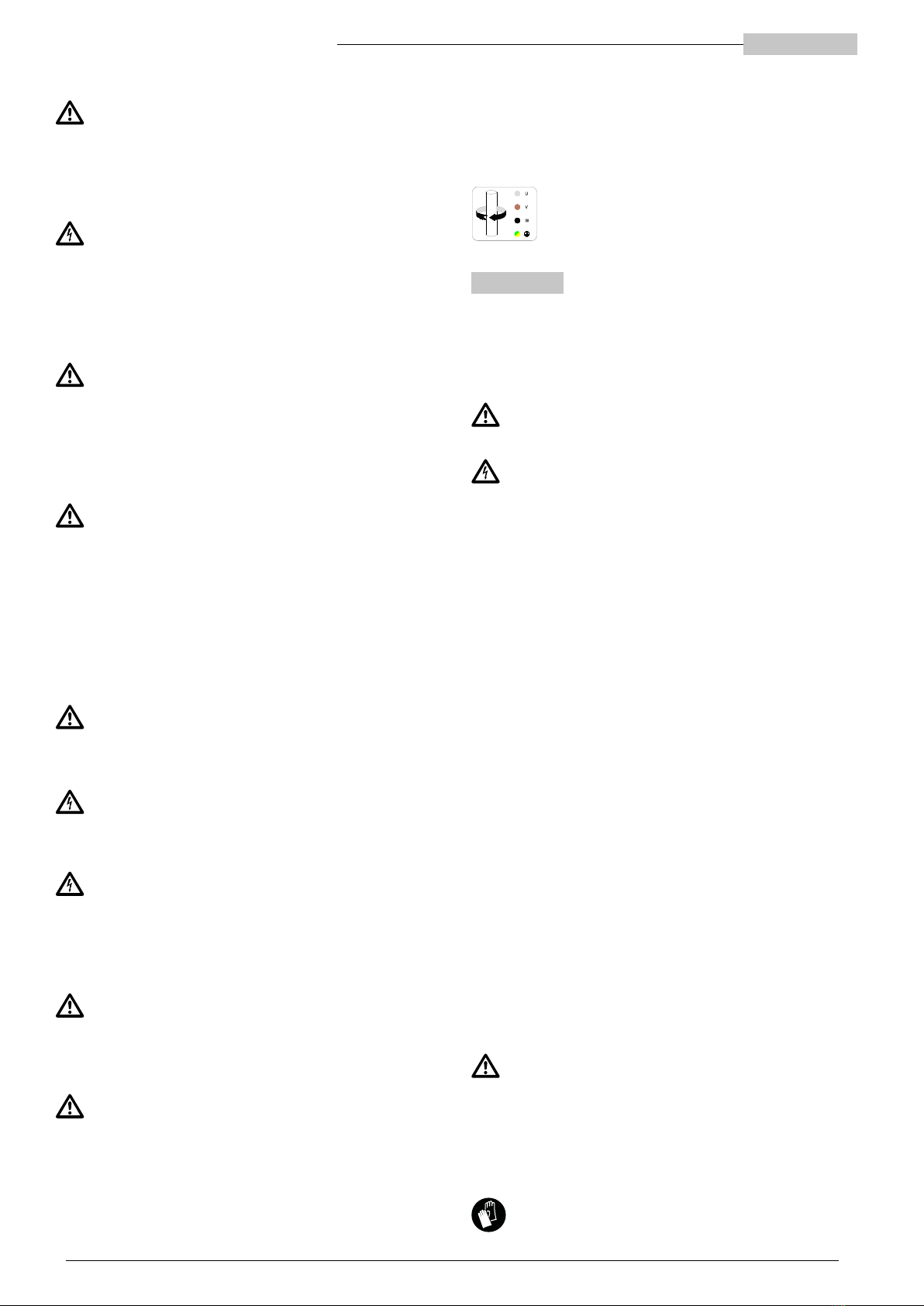
Electrical connection and rotation direction of
functional components (three-phase motors).
SAFETY RULES
This instruction manual should be definitely referred to byall qualified technical
personnel in charge of installing, operating and servicing the appliance.
It should be properly kept and made available for reference on the installation site
of the electric pump.
Identification of the coded instructions provided in this manual
The safety notes in this instruction manual are marked with a general
hazard symbol. Failure to comply with them may cause serious damage
to health.
The safety notes marked with this symbol refer to electrical hazards.
Risks associated with failure to comply with safety rules
Failure to comply with safety rules may cause physical and material damage, as
well as environmental pollution.
Non-observance of safety rules may totally invalidate your warranty.
To name a few examples, failure to comply with these rules can result in:
• failure of the main machine functions or of the installation,
• impairment of maintenance operations,
• physical harm due to electrical or mechanical causes.
General
This appliance (pump or electric pump, depending on the model) was designed
and manufactured according to the most cutting-edge techniques, in full
compliance with the regulations in force, and subjected to strict quality control
procedures.
This instruction manual will help you not only to understand how the appliance
works, but also to get to know its possible applications.
This user manual contains important recommendations that are necessary for the
appliance to be properly and economically operated. These recommendations
must be observed in order to ensure reliability and durability, and to avoid any
risks of accidents resulting from improper use.
The appliance must be used for the intended applications and within the limits
described in the following paragraphs.
The activities related to handling, installing, using, servicing and disposing of
the product pose risks for human safety and for the environment that cannot be
constructively eliminated.
The main residual risks are electrical (electrocution) and mechanical ones
(injuries caused by sharp edges, abrasions or crushing).
All operations must be carried out with the utmost attention only by expert,
professional sta, equipped with appropriate personal protective equipment
and suitable tools, when the machine is disconnected. Failure to observe the
instructions provided in this manual and proper working practices will increase
health risks.
The manufacturer accepts no responsibility in case of accident or damage
caused by negligence, improper use of the electric pump, or failure to follow
the instructions described in this manual, or use in conditions other than those
permitted.
In the supply conditions, the electric pump has no moving or normally live parts
accessible from the outside.
The user must not disassemble the electric pump completely or partially,
nor make any changes or tamper with the product. If removed during
installation, guards must be refitted immediately.
Personal Protective Equipment (PPE)
During installation, routine and extraordinary maintenance, decommissioning
and disposal, use the personal protective equipment (PPE) specified below.
Additional PPE may be necessary, depending on the working conditions.
By properly using PPE, any residual health risks may be reduced.
Wear safety gloves
Translation of the original instructions
ENGLISH 5" CLOSE-COUPLED PUMPS
Protect your eyesight with safety goggles
Wear steel toe cap safety shoes, insulated from the ground
Wear a respirator if there is a risk of toxic, irritating or suocating fumes
Suitable clothing
During maintenance operations and in any case when the machine is
running in various modes, including its normal operating mode, avoid any
clothing or accessories that may get entangled in the moving parts of the
machine.
Declaration of conformity
The declaration of conformity, including the rules and regulations considered in
the design phase, is shown at the end of the manual.
Noise emission
The electric pump generates an A-weighted acoustic pressure lower than 70
dB(A).
1 PRELIMINARY INSPECTION
1.1 Delivery and packaging
The product is supplied in its original packaging, which includes this instruction
manual, and must remain packed until it is installed. The packed product must be
stored away from atmospheric agents.
Remove the appliance from the packaging and check that it is intact. Also check
whether the rating plate details match the desired ones. To properly read the
rating plate, refer to the instructions in this manual. In case of any discrepancies,
contact the supplier immediately, specifying the nature of the defects.
If in doubt about the machine safety or integrity, do not use it and contact
a professional service centre.
2 PRODUCT INFORMATION
The product model, main service specifications and serial number are shown
on the rating plate. It is important to provide these details when requesting
interventions or support and spare parts.
The product model is identified by an alphanumeric code shown on the rating
plate. The meaning of the characters making up the code is explained in Fig. 1.
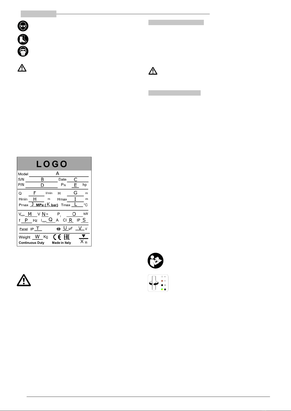
2.1 Pump rating plate
To properly read the rating plate, refer to the following instructions (Fig. 2). Please note that the information provided on the rating plate may be arranged dierently
from what is shown below. Refer to the symbols describing the reference fields.
Some information may not be available, depending on the model considered.
A) Pump identification code
B)Serial number
C) Production date
D)Product code
E) Rated power
F) Operating flow range
G)Operating head range
H)Minimum head (according to EN 60335-2-41)
I) Maximum head
J) Maximum pressure in MPa
K)Maximum pressure in bar
L) Maximum operating temperature
M)Rated power supply voltage
N)"3" (three-phase version) / "empty" (single-phase version)
O)Maximum power absorbed by the electric pump
P) Rated power frequency
Q)Current consumption
R)Insulation class (motor windings)
Fig. 2
S) Degree of protection of the electric pump
T) Degree of protection of the control panel (if present)
U) Capacitor capacity (single-phase motors)
V) Maximum capacitor voltage
W) Electric pump weight
X) Maximum immersion depth
2.2 Other plates
On the surface of the pump, there may be other plates depending on the model
that identify its features, compliance with rules and regulations or installation, use
and disposal provisions. See the following list.
Pay attention to the risks associated with the product installation,
maintenance and disposal.
Before installing and using the electric pump, carefully read the
instruction manual.
Rotation direction of functional components (three-phase motors).
Use and installation instruction manual ENGLISH
3 APPLICATIONS AND USE
3.1 Permitted use
These electric pumps are designed for applications such as water supply from
groundwater, pumping from a reservoir or tank, pressure increase or domestic
and small commercial or industrial utilities.
The electric pumps have an IPX8 protection rating.
The submerged electric pumps are designed to work while immersed in the liquid
and the surface electric pumps to work out of the liquid. The control panel has an
IP55 protection rating.
3.2 Pumped liquids
Clean, non-aggressive liquids, compatible with the electric pump component
materials. A liquid must have physical characteristics similar to those of clean
water at room temperature (1030 kg/m3maximum density and 2 cPs maximum
viscosity. If these limits are exceeded, contact the manufacturer).
Improper use can result in overheating of the machine and power cables,
with consequences such as failure and potentially fire.
Anysand contentinthewatermustnot exceed50g/m3.Highersandconcentration
will reduce the electric pump service life and increase the risk of blockage. Any
suspended solids must not exceed 0.5 mm in maximum size.
The pump can work continuously at the maximum temperature indicated on the
rating plate.
3.3 Conditions of use
• Maximum operating pressure (pump delivery pressure, given by the sum of the
pump inlet pressure and the pressure increase created by the pump): 15 bar.
The maximum pressure at the appliance inlet is determined by the pressure
increase created by the pump, so as not to exceed the maximum operating
pressure (see appropriate section).
• Sucked liquid maximum temperature: +40°C.
• Electrical supply voltage: refer to the rating plate.
• Maximum immersion depth: see the indication of the rating plate (max 20 m).
• Maximum number of consecutive hourly start-ups: 40.
3.4 Non-permitted use
Do not use the electric pump for applications other than those described
above and, in any case, not authorised by the manufacturer. Improper use may
cause serious damage (including death) to people, animals, objects and the
environment.
Do not use the electric pump in swimming pools, basins, ponds and in
similar places when people are in the water.
• Do not pump food liquids or human food products.
• Do not pump drinking water if adequately certified equipment is required for
this.
• Do not pump any liquids that are more viscous and/or denser than water,
unless specifically authorised by the manufacturer.
• Do not use the machine in potentially explosive environments or with
flammable liquids.
• Do not run the machine without any liquid.
• To avoid overheating, do not run the electric pump continuously at a flow rate
of zero or lower than 10% of the rated value. The pump is operated at best
within the range specified on the rating plate.
4 INSTALLATION – GENERAL
The electric pump is suitable for both vertical and horizontal installation. Electric
pumps with in-line ports can be installed in places occasionally subject to flooding
(as long as the electrical terminals of the power cable remain in a dry place).
The wire terminals of the power supply cable (wires or power outlet) must be
protected against water, humidity and atmospheric agents. Pay attention to the
protection rating of the control panel (IP55), if any.
Secure the control panel to the wall using the eyelets on it. It is recommended to
install it in a dry and sheltered place.
Before starting work on the machine, make sure that it has been
disconnected from the power supply network and that it cannot be
accidentally reconnected.
Always use the required PPE (refer to the relevant section).
If necessary in relation to the conditions of use and the working environment, we
suggest installing adequate devices to immediately but safely stop the machine,
in case of emergency.
4.1 Electrical connections
The connections must be exclusively performed by expert, authorised personnel
and in compliance with legal obligations, current regulations, recommended
technical practices and the following provisions.
Models without a plug are only intended for fixed applications (where the cables
cannot be disconnected and reconnected by the user). The cable terminals
must be connected in an electrical panel with at least an IP55 protection rating,
equipped with cable mechanical fixing systems independent of electrical
terminals, and an overvoltage category III omni-polar cut o switch preventing
the panel from being opened when the appliance is live.
Models equipped with plugs can be used in mobile applications, using only
electrical sockets provided with an earth contact. The following provisions apply
to both types.
Make sure the rating plate details match the rated voltage and frequency values.
Always connect the earthing cable of the electric pump and check the earthing
circuit for eectiveness before starting the pump up and on a regular basis.
The installer is responsible for making connections in accordance with the
regulations in force in the country of installation.
The appliance must be powered by means of a residual current device,
with residual operating current not greater than 30 mA.
Three-phase appliances must be protected against short-circuits and overloads
by a class 10 protection device, in accordance with IEC 60947-4. Set the rated
current according to the value shown on the rating plate. A manual reset device
is recommended.
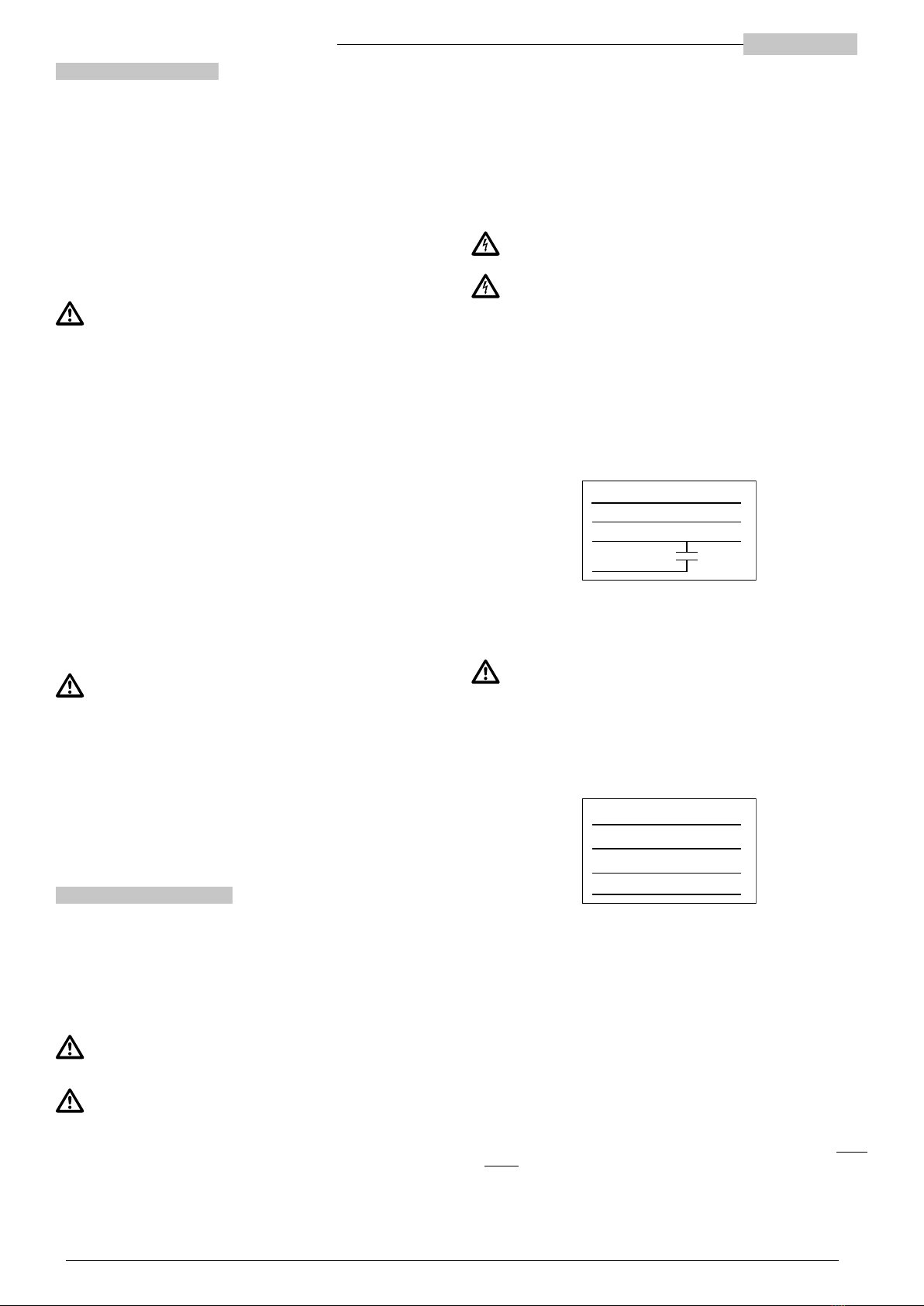
4.2 Single-phase versions
The single-phase versions can be supplied complete with a control panel that
includes the capacitor or with the integrated capacitor (two-wire power cable, in
addition to the earth wire).
Otherwise, refer to the instructions below (fig. 3) and to the technical data plate
of the pump for the connection and when choosing the capacitor.
BLACK
BLUE or GREY
BROWN
Fig. 3
C
L
N
YELLOW/GREEN
⏚
In the single-phase versions up to 1.1 kW (50 and 60 Hz) and 1.5 kW (50 Hz),
the motor is protected against overloads by means of a thermal device (circuit
breaker) inserted in the winding.
Caution! The device automatically resets when the motor temperature
dropsbelowthedangerlevel.Theelectricpump mayrestartunexpectedly!
The single-phase powers 1.5 and 2.2 kW require external protection, if not
equipped with the control panel.
The rotation direction does not require any checks.
4.3 Three-phase versions
To connect the three-phase versions, refer to the indications below (fig. 4).
Fig. 4
BLUE or GREY
BROWN
BLACK
U
V
W
YELLOW/GREEN
⏚
Three-phase versions require external protection against overload and short-
circuit.
If the electrical connections have been made respecting the cyclic direction of
the phases, as in fig. 4, the direction of rotation is automatically corrected (it is
advisable to verify in any case, so as to avoid misunderstandings). Otherwise,
check the direction of rotation as described below.
4.3.1 Checking the direction of rotation
In the three-phase versions, the direction of rotation is determined by the
connection of the power supply and can be inverted. In this case, the performance
is significantly lower than the nominal ones. To check the correctness of the
connection, immerse the electric pump in the fluid to be pumped or install it in
line. Start it and proceed in one of the following two ways:
• During operation, measure the maximum power consumption with an
ammeter clamp. If the rotation direction is incorrect, the values will be nearly
double those specified on the rating plate.
• Alternatively, run the machine for a few seconds, then reverse the rotation
direction and repeat the operation. The correct direction is the one in which the
greatest flow rate is obtained.
To reverse the rotation direction, it is sucient to exchange two phases between
them.

Translation of the original instructions
ENGLISH 5" CLOSE-COUPLED PUMPS
4.4 Variable frequency drive (VFD) applications
For variable frequency installations (power supply via “inverter”), make sure the
frequency inverter can supply the rated voltage and at least 10% more current
than the rated value shown on the rating plate. To install and connect the device,
please refer to the manufacturer's instruction manual.
5 HYDRAULIC CONNECTIONS
Before starting any work on the electric pump or the motor, make sure
that the power supply is disconnected and it cannot be accidentally
restored.
Installing the electric pump can be complex and dangerous for people.
This operation must, therefore, be performed by competent, qualified
installers.
In case of breakage, the electric pump can release up to 50 cl of oil. Occasional
ingestion of oil is not dangerous for human health. The risk of an oil leak should
be limited as much as possible. Plan it during installation.
Refer to fig. A1 (submerged installation) and fig. A2 (surface installation) in the
appendix.
5.1 Delivery piping
The pipe diameter determines the flow rate and pressure available at the points
of use. Small diameter pipes reduce performance and increase water hammers
and the risk of cavitation. Adopt flow cross-sections as great as the piping length
(possibly with a larger diameter than that of the port of the electric pump).
It is advisable to install a non-return valve (B in fig. A1 and fig. A2), to avoid
emptying the delivery pipe following the shutdown of the electric pump and to
avoid backflow. Firmly tighten the piping on the port, without damaging it. The
electric pump can be installed both with a metal pipe and one in other material.
If you intend to use the delivery pipe to support the pump (e.g. fig. A1 and fig.
A2, left side), always check that it is suciently strong and rigid to withstand the
combined action of the starting torque, the liquid pressure, the vibrations and the
electric pump weight. Alternatively, in the case of submerged installations, it is
advisable to support the electric pump with a metal cable firmly secured to the
eyelet of the head and constrain the electric pump with respect to rotation. For
surface installations, the electric pump can be supported by securing it directly
with clamps (D in fig. A2, right side).
5.2 Installation in the well
The maximum diameter of the electric pump is 129 mm. Check that the well has
no restrictions or obstacles hindering the descent of the electric pump. The gap
between the electric pump and the walls of the well must be adequate for the
required flow rate. An internal well diameter of at least 140 mm is recommended.
The motor is cooled by the water flow inside the electric pump. Therefore, a
minimum speed value is not required.
Secure the power cable to the delivery pipe using specific clamps (fig. A1).
Do not underestimate the risk of falling and drowning if the installation is to be
carried out in a large well, in a tank or in a reservoir.
Make sure that there is no risk of toxic, suocating fumes or harmful or potentially
explosive gases in the work atmosphere. Use appropriate PPE, if necessary.
It is recommended to check that the well is not obstructed along its entire length.
Lower the electric pump into the well to avoid damaging the electric cable.
Do not use the power cable to lower or support the electric pump in the well.
5.2.1 Minimum and maximum immersion
In order not to draw in air through the filter, the electric pump must be immersed
in the liquid up to at least half its height and in any case, not less than 30 cm from
the bottom (MIN level in fig. A1). Ensure sucient immersion so as to guarantee
this condition when the liquid in the well reaches the minimum level. Dry running
or with air mixed with liquid can cause serious damage to the electric pump and
irregular performance.
The maximum immersion depth (MAX level in fig. A1) is shown on the rating plate.
5.2.2 Models with float
The models fitted with a float start automatically when the float exceeds
approximate angle of 45° with respect to the horizontal line. The motor stops
automatically when the float drops below the horizontal line again. During
installation, it is necessary to verify that:
1) The float is free to move in both directions without getting stuck or caught.
Remove any obstacles. Check all the space around the electric pump, in all
directions allowed.
2) The electric pump only starts when the liquid reaches a level that is at least
equal to the minimum prescribed immersion (see the previous section) and
stops before the liquid drops below this level. Adjust the free length of the float
cable to achieve the desired result.
5.3 Surface installation
Models with in-line ports are designed to be installed between two pipe sections.
Refer to fig. A2 in appendix.
Make sure that the misalignment between the two pipes does not generate an
excessive load on the electric pump connections. It is advisable to install a flexible
section on at least one of the two sides (E in fig. A2). Adequately support the
pipes so as to avoid transmitting excessive force or torque to the ports of the
electric pump.
We recommend installing shut-o valves on the outlet and, if the line is
pressurised, at the pump inlet, so as to perform maintenance without draining
the hydraulic system (C in fig. A2).
If the electric pump sucks from a non-pressurised line (e.g. a well or a tank, at a
higher height than that of the exposed surface) it is necessary to install a foot or
non-return valve along the suction pipe to prime the pump (B in fig. A2).
The pump does not have a filler cap. If the pump is installed with suction life, it is
advisable to install a fitting that allows air to be filled and vented.
5.3.1 Checking the maximum suction pressure and NPSH
It is necessary to check that the sum of the suction pressure (P in) and the
maximum pump pressure increase (H max, in bar) is lower than the maximum
pump pressure (P max, in bar). In any case, the maximum suction pressure must
not exceed the value on the rating plate.]
Also check that the NPSH available at the electric pump inlet is higher than the
value required by the pump and take an adequate safety margin into account
so as to avoid the risk of cavitation. To calculate the available NPSH, use the
following formula:
NPSH = pb x 10.2 - Hv – Hs
pb: Absolute pressure of the liquid being sucked, with a running pump [bar].
Hv: Vapour pressure [m] depending on the liquid temperature [m]
Hs: Safety margin [m] (minimum 0.5)
The required NPSH values are specified in the characteristic curves shown in the
appendix (fig. A3). Look for the frequency (columns) and family (rows) reference
charts.
If the required NPSH value (fig. A3) exceeds the available NPSH value calculated
with the above formula, the pump with negative suction head must be installed
at a depth, in metres, equal to the dierence between the two values. In closed
circuits, install the water pump unit/expansion vessel at the pump inlet and
pressurise the circuit.
6 MECHANICAL INSTALLATION
6.1 Machine handling
To lift the machine, use only suitable, properly marked devices (e.g. CE marking)
in good working condition. Do not exceed the load capacity of the least resistant
device among all those used (lifting lug, shackle, hook, carabiner, chain, rope,
hoist or other). Only use hooks with safety triggers. Use adjustable lifting lugs or
check their maximum load capacity for non-axial loads.
Pay attention to suspended loads. Do not stand under them. Pay attention
to people, animals and objects in the work area. Use appropriate work
area marking tools and delimiters, where necessary. Do not operate the
pump or let it pass over people.
The appliance can be moved manually.
Check the mass indicated on the rating plate and/or on the packaging.
6.2 Fastening
Secure the unit so that it remains stable and cannot move during operation, using
the delivery pipe or by securing the pump body directly.
Models equipped with brackets must be fixed using these methods.
7 START-UP AND PROLONGED STOP
Before starting the electric pump, it is necessary to fill it and the suction pipe with
water (the whole circuit, if the plant is closed). If an electric pump with positive
suction head is installed, perform the following operations manually.
Otherwise, if a negative suction head system is installed or the suction line is
pressurised, it is sucient to open the valves, vent the air and wait for filling. In
closed circuits, load the system from the highest point and vent air at the same
time. During the first few seconds of operation, the pump will expel further air. If
the circuit is closed, vent it with appropriate valves.
Pay attention to leaks. Use appropriate PPE to protect against mechanical
and chemical risks.
Slowly open the valves during venting, avoiding sudden manoeuvres; do
not direct the jet towards people, animals or electrical appliances.
After prolonged downtime, check the pump for proper priming before starting it,
and vent the pipes, if necessary.
If a long period of inactivity is foreseen and/or the machine needs to be emptied
of liquid, disconnect it from the pipes and tilt it to let the liquid out.
Use and installation instruction manual ENGLISH
8 MAINTENANCE AND SUPPORT
The electric pump does not require special maintenance.
Havetheelectricpumprepairedonlybypersonnelauthorisedbythe manufacturer
so as to keep your warranty valid and not to impair the safety of the appliance.
Use only original spare parts or parts approved by the manufacturer.
Always use the required PPE (refer to the relevant section).
Before starting any work on the electric pump, make sure it has been
disconnected from the power supply and cannot be accidentally
reconnected.
Caution! In the event of an overload shutdown, appliances equipped with
automatic reset circuit breaker switches will automatically restart when
the temperature drops below the danger level.
It is advisable to check the condition of cables (especially at the cable glands)
every month and clean the filters and/or suction grille.
If the power cable is damaged, it must be replaced by the Manufacturer,
their service centre or qualified personnel.
8.1 Spare parts
Use original spare parts or parts approved by the manufacturer, in order to avoid
any risks to the service personnel’s and users’ health. Contact the supplier and/or
check the spare parts tables (see technical catalogue) for information.
9 EMERGENCY MANAGEMENT
9.1 Fire
• The only machine part exposed to a fire hazard is the motor and does not
involve any of its external parts.
• In the event of a fire, use extinguishers approved for electrical devices
9.2 Liquid spills
• The pumped liquid may escape from the machine as a result of installation,
start-up, maintenance or disposal, unforeseen breakages or excessive wear of
sealing devices.
• If spills can be dangerous or harmful to human, animal or environmental
health, install a waterproof collecting basin around the machine.
9.3. Oil spills
• In case of breakage, the electric pump can release up to 50 cl of oil (non-toxic).
Occasional ingestion of oil is not dangerous for human health. The risk of an oil
leak should be limited as much as possible.
10 TROUBLESHOOTING
For the solution of problems related to the electric pump operation, follow the
instructions in the table below. If you do not have the necessary knowledge and
skills, contact qualified personnel. Always use PPE (see relevant section) and
appropriate tools. If the problem cannot be solved by following the instructions in
the table, contact a professional, authorised service centre.
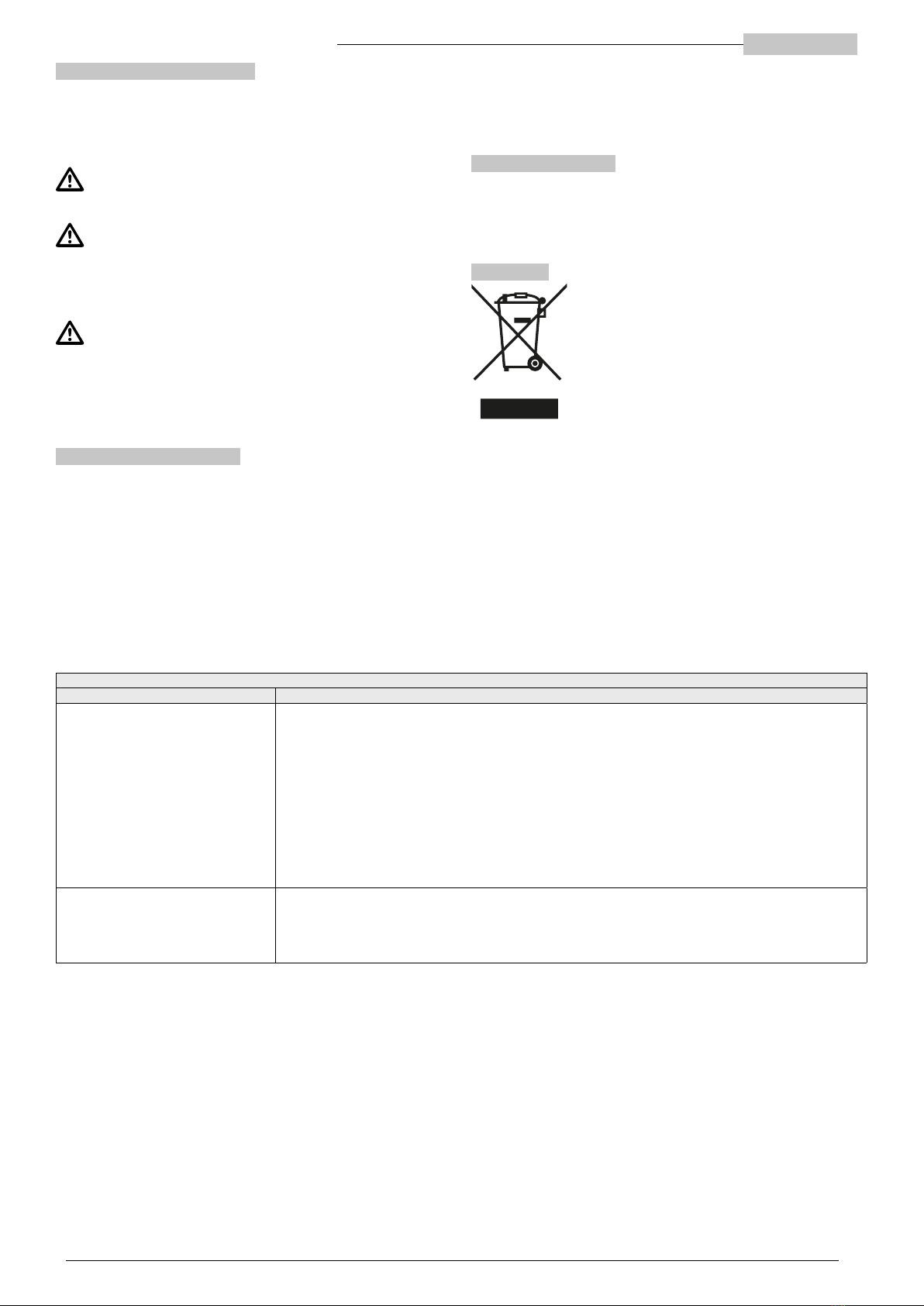
11 DISPOSAL
The devices marked with this symbol may not be disposed
of in domestic waste but disposed of in appropriate local
collection centres for Waste Electrical and Electronic
Equipment (WEEE), or delivered to the distributor who is
required to collect them.
Domestic WEEE (single-phase electric pumps with <3 kW
power) must be handed in to private or local collection
centres, retailers or repairers, at no cost.
Industrial WEEE (all products not classified as domestic)
must be delivered to specific collection centres or retailers
or repairers.
The product is not potentially dangerous for human health and the environment
as it does not contain any harmful substances pursuant to Directive 2011/65/
EU (RoHS), but if released into the environment it will adversely impact the
ecosystem.
The illegal or improper disposal of the product involves severe criminal and/or
administrative penalties.
11 TROUBLESHOOTING
FAULT/MALFUNCTION SOLUTION
1) The electric pump does not get started
or stops unexpectedly
• For single-phase models with a control panel: check that the switch is set on “I”. If the manual reset thermal
magnetic switch is present, press the reset button. Check that the capacitor is intact.
• For single-phase models without a control panel: check that the installed capacitor is correct, connected correctly
and undamaged.
• For models with a float, check the travel of the float and lift it manually to check that it works.
• Check whether the circuit breakers and residual current devices have been enabled; check that fuses (if any) are
intact.
• Check the electrical connection to the mains.
• Make sure the mains supply voltage is on.
• FOR PROFESSIONAL MAINTENANCE TECHNICIANS ONLY: make sure the pump can rotate freely and power
consumption does not exceed the value on the rating plate.
2) The electric pump gets started but
does not deliver any flow, dispenses
irregularly, or the flow rate is much
lower than values specified on the
rating plate
• For submerged units: check that the filter is not clogged and that the pump is submerged at least to the specified
minimum limit
• For surface units: check that the pump is primed and does not cavitate
• Make sure there is no air in the hydraulic conduit; vent pipes
• For three-phase models: check the rotation direction

APPENDICE / APPENDIX / APPENDICE / ANHANG / APÉNDICE / / BIJLAGE / LISA / PRIEDAS / PIELIKUMS
/ ZAŁĄCZNIK / ПРИЛОЖЕНИЕ / BILAGA / EK / LIITE
APPENDIX
Fig. A1 Fig. A2
MIN
MAX
A
B
00130212OPM 03/2019
A
D
D
A
C
C
A
A
EE
E
B
00130213OPM 03/2019
Table of contents
Popular Water Pump manuals by other brands

Crane
Crane Barnes UltraSTEP installation manual

MDM
MDM ValuFlo 750 Installation and service manual

Sotera
Sotera FILL-RITE SV Series Owners installation, operation, and safety manual

Kremlin-Rexson
Kremlin-Rexson EOS 60-C980-HD manual

TE Connectivity
TE Connectivity 314979-1 Customer's manual

ubbink
ubbink Cascademax Series manual

Xylem
Xylem GEMK Installation, operation and maintenance instructions

Kremlin-Rexson
Kremlin-Rexson AIRMIX 08-120 Disassembly/Reassembly

Grundfos
Grundfos SR Installation and operating instructions

Grundfos
Grundfos DB instructions

Everbilt
Everbilt UT03301 Use and care guide

dosatron
dosatron D9 Green Line owner's manual


