Forbo siegling blizzard HP 160/400 AIR User manual
Siegling – total belting solutions
OPERATING MANUAL
BLIZZARD HEATING PRESS
Contents
3 English manual
27 German manual
siegling blizzard
splicing equipment
TM

2
Dieses Gerät darf nur von Personen
in Betrieb genommen werden, die
die nachfolgende deutsche oder englische
Betriebsanleitung gelesen und verstanden haben.
Този уред се допуска да се въвежда в
експлоатация само от лица, които са
прочели и разбрали следващото немско или
английско ръководство за експлоатация.
本设备只能由已阅读并了解以下英文、
中文或日文用户手册的人员使用。
Dette apparat må kun sættes i drift af
personer, som har læst og forstået den
følgende tyske eller engelske driftsvejledning.
This device should only be used by those
personnel who have read and understood
the following German or English user manual.
Seda seadet tohivad kasutusse võtta vaid
inimesed, kes on lugenud allpool esitatud
saksa- või eestikeelseid kasutujuhiseid ning neist
aru saanud.
Tämän laitteen saavat ottaa käyttöön vain
sellaiset henkilöt, jotka ovat lukeneet ja
ymmärtäneet seuraavan saksan- tai englanninkieli-
sen käyttöohjeen.
Cet appareil ne doit être mis en service
que par des personnes ayant lu et compris
les instructions de service ci-après en allemand ou
en anglais.
Αυτή η συσκευή επιτρέπεται να τεθεί
σε λειτουργία όνο από άτοα που έχουν
διαβάσει και κατανοήσει τι οδηγίε χρήση που
ακολουθούν στα Γερανικά ή στα Αγγλικά.
Questo dispositivo può essere utilizzato
solo da persone che hanno letto e com-
preso il seguente manuale in tedesco o inglese.
この装置は、次の英語、中国語または日本
語の取扱説明書をよく読んで理解した作
業員のみが使用するようにしてください。
Ovaj uređaj smiju puštati u rad samo
osobe koje su pročitale i razumjele upute
za uporabu u nastavku koje su napisane na
njemačkom ili engleskom jeziku.
Šo ierīci drīkst lietot tikai personas, kuras
ir izlasījušas un iepazinušās ar turpmāk
redzamo lietošanas instrukciju vācu vai angļu
valodā.
Šį prietaisą leidžiama pradėti eksploatuoti
tik asmenims, perskaičiusiems ir supra-
tusiems toliau pateiktą vokišką arba anglišką
instrukcijų žinyną.
Dit apparaat mag alleen door personen
in gebruik worden genomen die de
volgende Duitse of Engelse gebruiksaanwijzing
hebben gelezen en begrepen.
To urządzenie może być użytkowane
tylko przez osoby, które przeczytały i
zrozumiały następującą niemiecką lub angielską
instrukcję obsługi.
Este aparelho só pode utilizado por
pessoas, que tenham lido e compreendi-
do o Manual de instruções em alemão ou inglês
que se segue.
Acest aparat poate fi pus în funcţiune
doar de către persoanele care au citit și
au înţeles instrucţiunile de utilizare de mai jos în
limba germană sau engleză.
Bara personer som har läst och förstått
den här bruksanvisningen på tyska eller
engelska får ta den här apparaten i drift.
Toto zariadenie môžu uviesť do pre-
vádzky len osoby, ktoré si prečítali nas-
ledujúci návod na použitie v nemeckom alebo
anglickom jazyku a porozumeli jeho obsahu.
To napravo smejo zagnati samo osebe,
ki so prebrale in razumele naslednja
nemška ali angleška navodila za uporabo.
Este aparato solo deben emplearlo las
personas que hayan leído y comprendido
las siguientes instrucciones de uso (en alemán o
inglés).
Tento přístroj smějí uvádět do provozu
pouze osoby, které si přečetly následující
návod k obsluze v německém nebo anglickém
jazyce a rozumějí mu.
A készülék üzembe helyezését csak olyan
személyek végezhetik, akik elolvasták
az alábbi német vagy angol nyelvű használati
utasítást és megértették annak tartalmát.
3
WRONG or IMPROPER use of this splice press can result in damage to the press
and/or physical harm. This manual contains important information about product
function and safety. Please read and understand this manual BEFORE operating
the press. Please keep this manual available for other users and owners before
they use the heating press.
4 Main components
5 Technical data
6 Introduction
7 General safety rules
8 Safe operation
16 Plans and schemes
20 Wiring diagram of the
power supply cables
22 Wiring diagram
26 Technical assistance/
Manufacturer‘s notification
EC Declaration of conformity
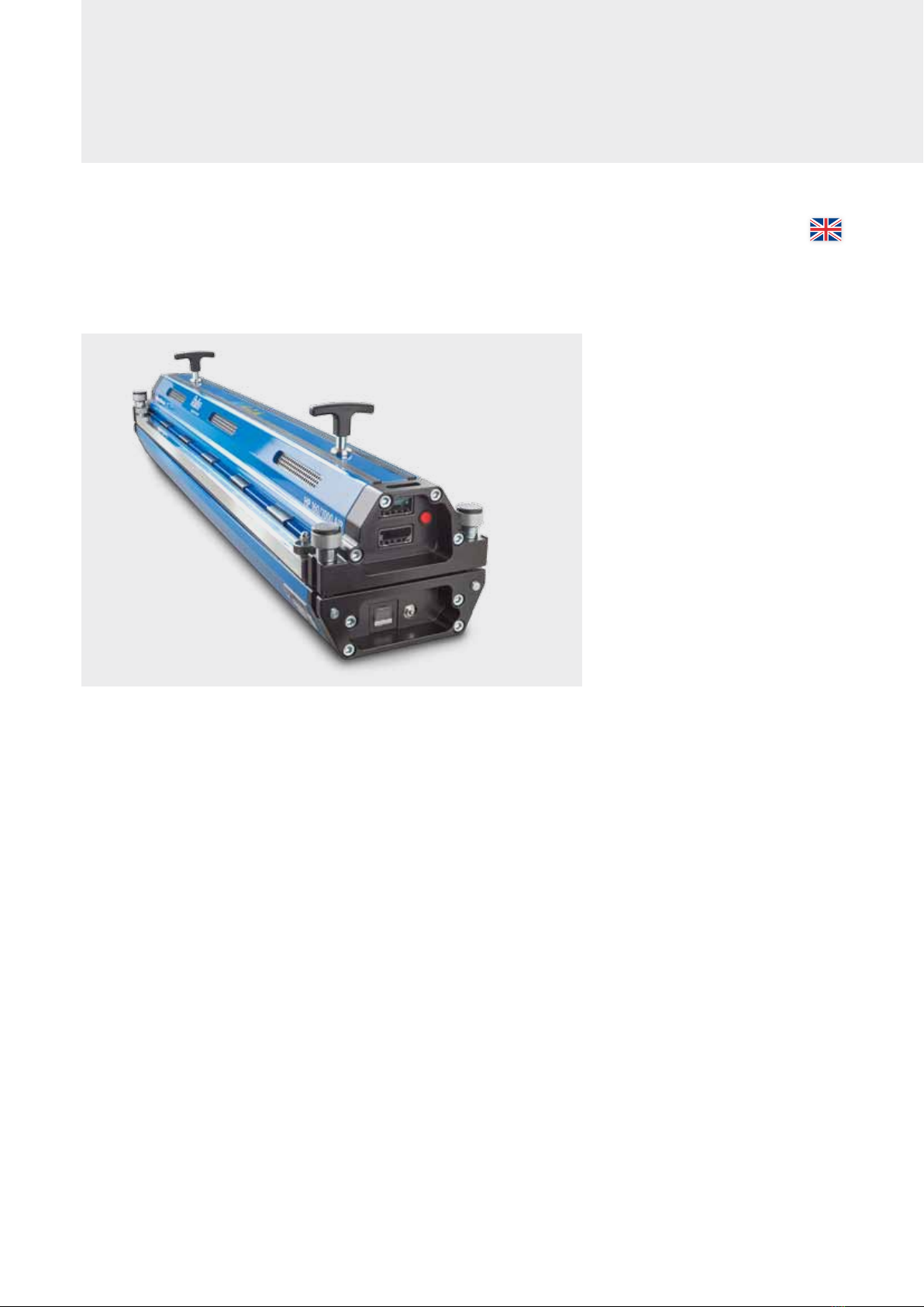
OPERATING MANUAL
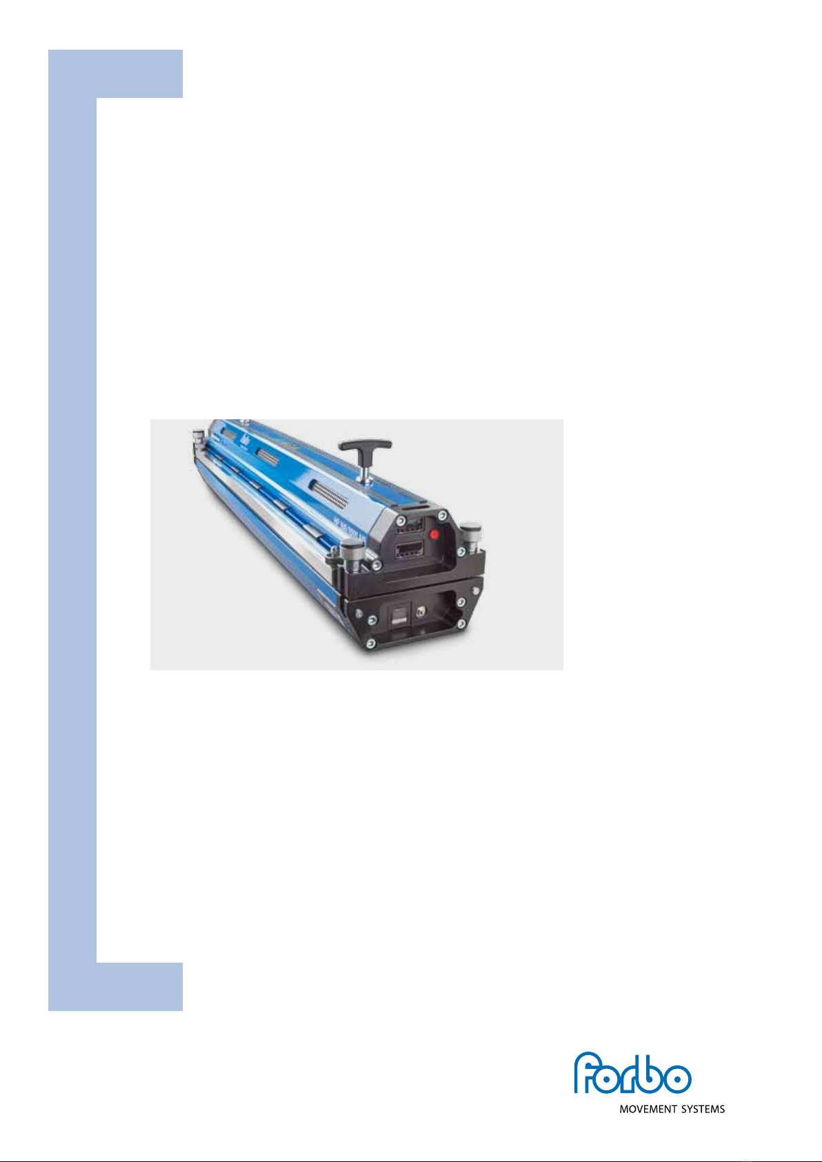
BLIZZARD HEATING PRESS

4
Top frame
Press connector bolts (4x)
Belt clamps nut (4x)
Belt clamps (2x)
MAIN COMPONENTS
Front connections
Front
controls
Handle
Front connections
Start button
Front controls
Timer
Top frame controller
Bottom frame controller
Air bleeder button
Pressure switch
Top jumper connection
Connection to the mains (inlet)
Bottom jumper connection
Bottom frame

5
230 (9.1)
84 (3.3) 84 (4.6)
Key dimensions
Key dimensions in mm and inches (in)
All imperial measurements have been rounded up.
TECHNICAL DATA
Delivery scope and accessories
The press will be delivered incl. cables transport
box as well an one set of silicone mats.
As accessories variant types of embossing mats,
glossy seperating paper an matt seperating
paper (VEZ) are available on request.
Blizzard
HP 160/400 AIR
Blizzard
HP 160/600 AIR
Blizzard
HP 160/800 AIR
Blizzard
HP 160/1000 AIR
Blizzard
HP 160/1200 AIR
Blizzard
HP 160/1500 AIR
Effective belt width [mm (in)] 400 (15.7) 600 (23.6) 800 (31.5) 1000 (39.4) 120 0 (47.2) 1500 (59)
Max. effective splice length
[mm (in)] 160 (6.3) 160 (6.3) 160 (6.3) 160 (6.3) 160 (6.3) 160 (6.3)
Weight Top part [kg (lb)] 12 (26.5) 15.8 (34.8) 19.1 (42.1) 22.5 (49.6) 26.2 (57.8) 31 (68.3)
Weight Bottom part [kg (lb)] 14.6 (32.2) 18.6 (41) 22.7 (50) 26.9 (59.3) 30.9 (68.1) 36.8 (81.1)
Total Weight [kg (lb)] 26.6 (58.6) 34.4 (75.8) 41.8 (92.1) 49.4 (108.9) 57.1 (125.9) 67.8 (149.5)
Length [mm (in)] 590 (23.2) 790 (31.1) 990 (39) 119 0 (4 6.8) 1390 (54.7) 1690 (66.5)
Width [mm (in)] 230 (9.1) 230 (9.1) 230 (9.1) 230 (9.1) 230 (9.1) 230 (9.1)
Height Top part [mm (in)] 118 (4.6) 118 (4.6) 118 (4. 6) 118 (4.6) 118 (4.6) 118 (4. 6)
Height Bottom part [mm (in)] 84 (3.3) 84 (3.3) 84 (3.3) 84 (3.3) 84 (3.3) 84 (3.3)
Max. pressure [bar (psi)] 2.5 (36.3) 2.5 (36.3) 2.5 (36.3) 2.5 (36.3) 2.5 (36.3) 2 (29)
Max. temperature [°C (°F)] 200 (392) 200 (392) 200 (392) 200 (392) 200 (392) 200 (392)
Transport dimensions (LxWxH) [mm] 875 x 370 x 350 875 x 370 x 350 1275 x 370 x 350 1275 x 370 x 350 1775 x 370 x 350 1775 x 370 x 350
Transport dimensions (LxWxH) [in] 34.5 x 14.6 x 13.8 34.5 x 14.6 x 13.8 50.2 x 14.6 x 13.8 50.2 x 14.6 x 13.8 69.9 x 14.6 x 13.8 69.9 x 14.6 x 13.8
Transport weight [kg (lb)] 42.1 (92.8) 49.9 (110) 61.9 (136.5) 69.5 (153.2) 83.8 (184.8) 94.5 (208.3)
Power requirements
1 phase [Volt / Amp/ Watt]
Art. No.
230 V/9 A / 2200 W
Art. No. 873399
110 V/14A / 1520W
Art. No. 873400
230 V/14A / 3200W
Art. No. 873401
110 V/14A / 1520W
Art. No. 873402
230 V/16A / 3680W
Art. No. 873403
110 V/14.5A/ 1600 W
Art. No. 873404
230 V/16A / 3680W
Art. No. 873405
110 V/14A / 1484 W
Art. No. 873406
230 V/16A / 3680W
Art. No. 873409
230 V/19.5 A /4500W
Art. No. 873412
230 V/16.0 A /3680 W
Art. No. 873413
230 V/13.0A / 3000 W
Art. No. 873414
3 phase [Volt / Amp / Watt]
Art. No.
400 V/11 A-5.5A-5.5 A/
7600 W
Art. No. 873407
400 V/12A-6.0 A-6.0A /
8990W
Art. No. 873408
480V/ 11 A-5.5 A-5.5 A /
8900 W
Art. No. 873410
400 V/16A-8.0 A-8.0 A /
11072W
Art. No. 873411
480V/ 13 A-6.5 A-6.5A/
10700 W
Art. No. 873415

6
INTRODUCTION
The Blizzard heating press is an all-in-one solution for splicing thermoplastic conveyor belts (e.g. PVC, polyurethane).
No external control box, air pump, or water cooling tank are required.
The heating presses are provided with electric heating and built in air cooling. The splice process runs fully automated.
If the belt is relatively thick a problem might occur where the outside of the belt is at the splicing temperature too long,
waiting for the inside to reach the required temperature. Melted material might flow away or discolor and fabrics might
shrink. To avoid this problem, the preheat option can be used. This option heats the belt up (outside and inside) to a tem-
perature just below the melting temperature. After the preheat stage, the inside splice temperature can be reached much
quicker, minimizing the risk for unwanted flow of material, discoloring or fabric shrinkage.
Basic process
• Splicepressureisappliedbyaninternalcompressor,
max. 2.5 bar (36.3 psi). Siegling Blizzard HP 160/1500 AIR:
max 2.0 bar (29 psi).
• Heatsuptoasplicetemperatureofmax.200°C(392°F)
• Keepsitatthesplicetemperature(adjustabledwelltime)
• Coolsdowntothecoolingtemperature
(safe temperature to take the belt out)
• Forthickerbeltsapreheattemperatureandpreheat
dwell time can be applied
• Thebottomheatingcanbesetlowerorhigherthan
the top heating
Graph of the basic process, program level 1
Settings:
Temperature
Time
Splicing
temperature
Dwell time
Cool down
temperature
(fans turn off))
Graph of a procss with prehating, program level 2
Settings:
Temperature
Time
Splicing
temperature Dwell time
Pre-heat
dwell time Cool down
temperature
(fans turn off)
Pre-heat
temperature
7
GENERAL SAFETY RULES
Signal words
“Danger” indicates an imminently hazardous situation
which, if not avoided, will result in death or serious injury.
The signal word is limited to the most extreme situations.
“Warning” indicates a potentially hazardous situation
which, if not avoided, could result in death or serious injury.
“Caution” indicates a potentially hazardous situation
which, if not avoided, may result in minor or moderate
injury. It may also be used to alert against unsafe practices.
Safety symbol
This international safety symbol is used to identify
and call attention to specific safety matters.
Overall safety rules
Danger
To avoid severe personal injury or property damage, read
carefully and understand the following safety precautions.
Danger
Terminate electrical hazards by removing power cord
from wall receptacle or machine base inlet.
Warning
Terminate pressure related hazards by pressing
the red pressure relief button.
Caution
Press platens develop over 5 tons of clamping force.
When operating the press keep the four press connector
bolts in place by hand tightening.
Caution
Avoid temperature related hazards by handling press
components and belt once safely cooled.
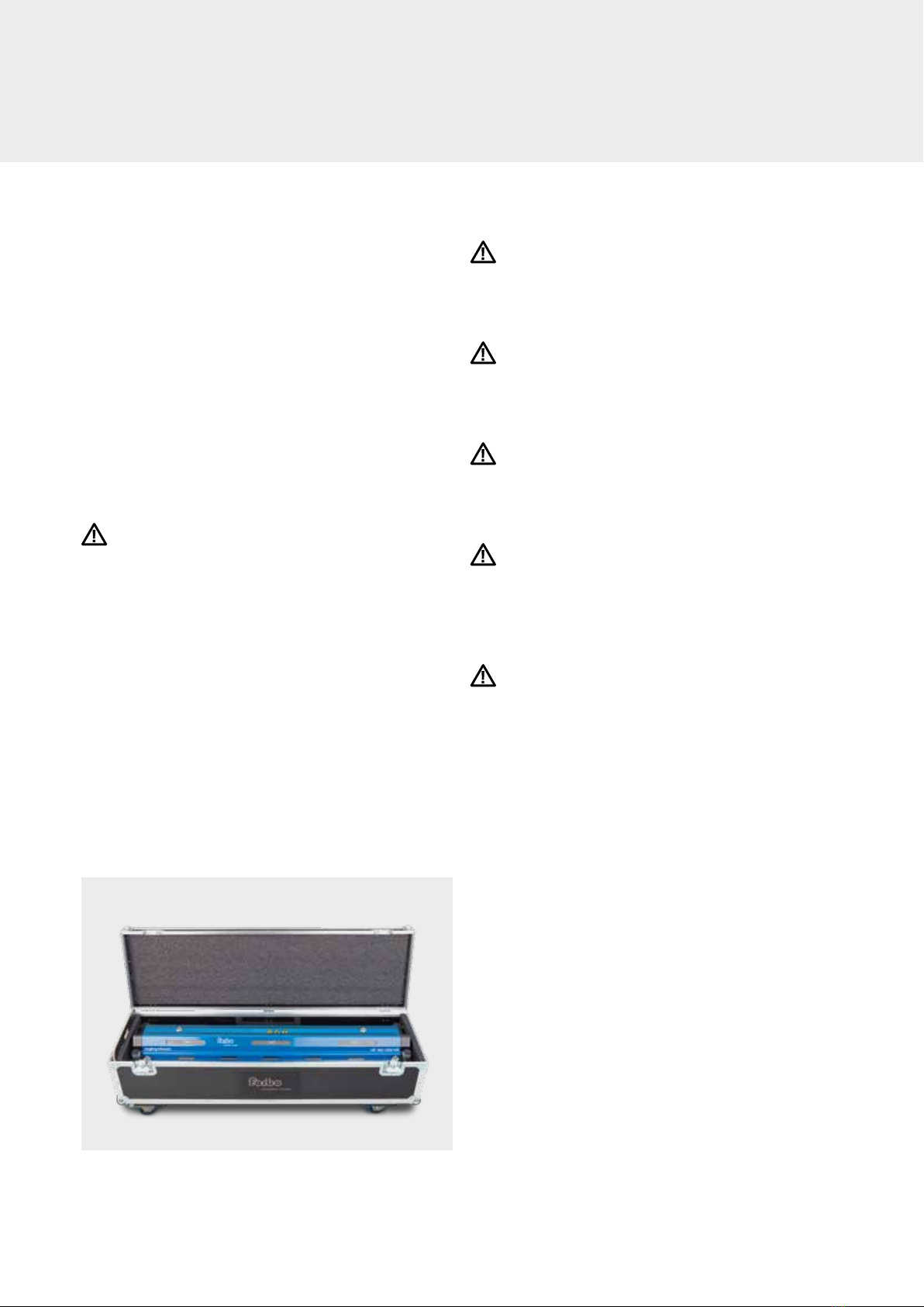
Flight case
• Blizzardheatingpressesaresuppliedwithaflightcasefor
both storage purposes and also for easy transport to
on-site jobs.
• SieglingBlizzard400–1500arepackagedinflightcases
with four wheels and an extension handle.
• Flightcasescanbestackedontopofeachother,butneed
to be secured during transportation.
• Allflightcasesfeatureanextendedhandleforeaseand
convenience in transport. Click in the grip of the flight case
to release the handle.
8
1
Locate a position in facility where appropriate voltage and power receptacles
are available to operate the heating press
Warning
Operating the press on incorrect voltage can cause serious damage and potential
hazards.
Before starting, ensure that you have enough belt material to cover the edges of the
press. The belt material for the edges must be the same type and have the same thick-
ness as the rest of the material.
2
Visually inspect power cord
Danger
a. Inspect cord for damage. Do not use power cord in a damaged state. Either replace
cord or have an electrician remove damaged section and reattach plug.
Electrician must refer to wiring diagram on page 22 for proper attachment.
b. Confirm compatibility between plug end and power receptacle. If incorrect,
find alternate power source or have electrician apply correct plug,
referring to wiring diagram on page 22.
Danger
c. Do not plug power cord into wall receptacle at this time. Later in the operation,
when ready to connect power follow these safe and proper operating procedures:
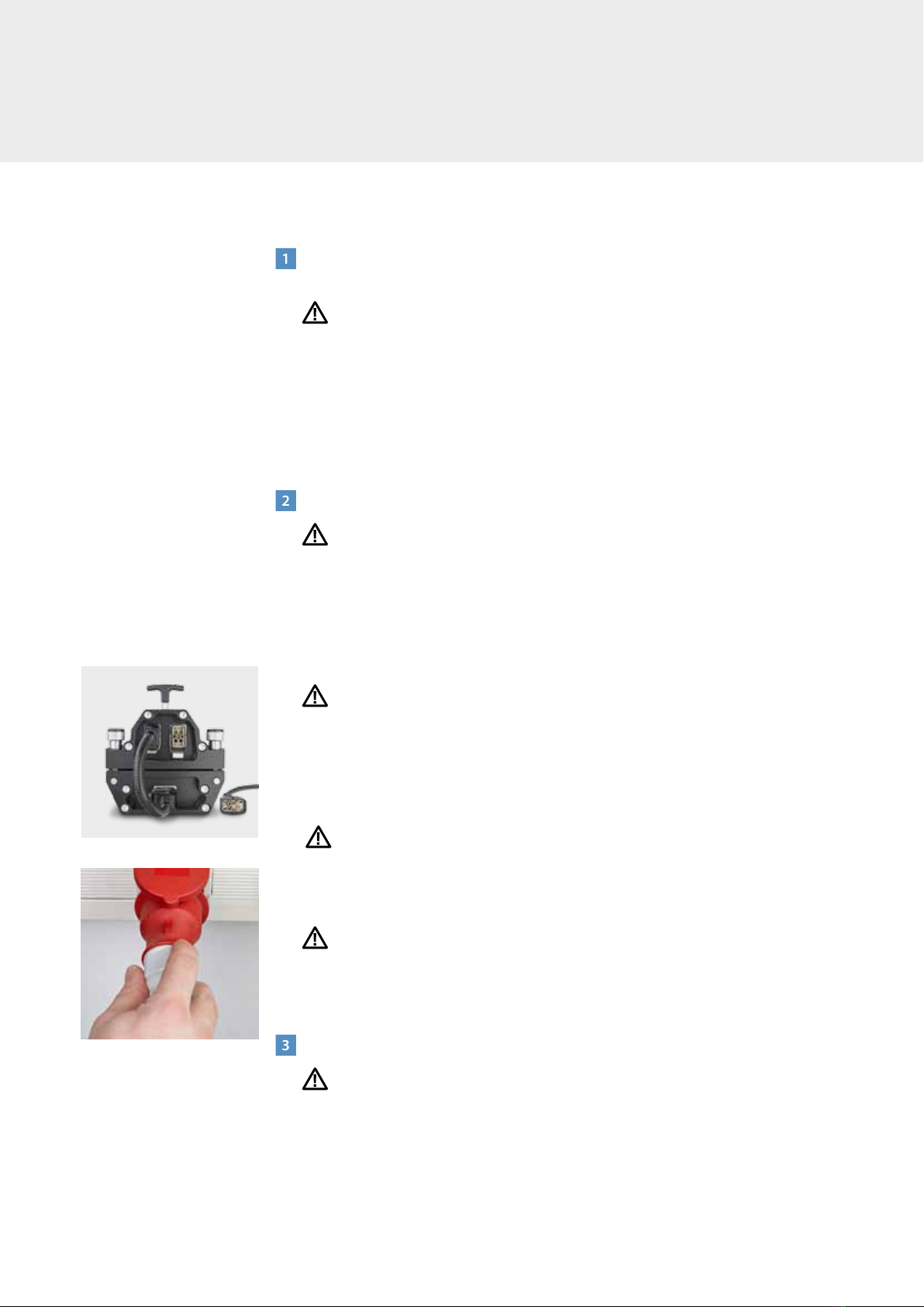
– First,connecttopandbottompresspartsbymeansofconnectioncable.(Fig.1)
– Second,plugpowercordintomachinebasepowerinlet.
– Third,insertplugendintowallreceptacle.(Fig.2)
Danger
– Neverleavepowercordpluggedintowallwhiledetachedfromunitasthiscould
lead to a serious electrical danger if it comes in contact with fluids, such as water.
Danger
d. All press power inlets and cable connectors have been supplied with keyed
(patterned) guide pins and bushings. This keying will prevent incorrect connection.
3
Remove press from flight case
Heavy object
Note: Use proper lifting techniques to avoid personal injury; ask for assistance for
removal from flight case if press is heavier than you are comfortable handling by
yourself.
Fig. 1
Fig. 2
SAFE OPERATION

9
4
Visually inspect press for damage
Warning
Broken or missing components can cause an unsafe working environment and
will likely cause additional damage to press and possible bodily injury.
Danger
a. Ensure all four press connector bolts are in good condition. Do not attempt to
operate the press if a bolt is broken or missing.
b. Inspect platens for potential damage.
c. Ensure platens are free of dirt/debris. If dirty, follow these cleaning instructions:
–Useammoniabasedcleanerswithcleantoweltogentlyremovedirt/debris.
Warning
– Donotcleanplatenswithaflammablesolution.
Caution
– Donotusewatertohosedowntheheatingpress.Ifpressneedstobecleaned,
use ammonia based solvent applied to a cloth and wipe down press. Dry press
with clean dry cloth.
d. Inspect all cables to ensure they are in good condition. If they are damaged,
do not use press until they are replaced.
5
Checking the heating press works
Forbo Siegling recommends inspecting the heating press twice a year.
Tools required
– Temperaturemeasurementdevice(accuracy±1°C)includingatemperaturesensor
– Pressuremeasurementdeviceincludingpressuresensor
– Straightedge
Use the tools listed to check the temperature, pressure and flatness of your Siegling
Blizzard heating press’s heating platens. If the heating press doesn’t comply with the
set parameters, we recommend sending in the heating press for calibration or repair.
Please get in touch with your Forbo Siegling contact for more details.
Warning
– Beforeapplyingthesensors,unplugtheheatingpressfromthepowersupply.
– Platensurfacesmaybehot.
6
Visually inspect silicone pads
Visually inspect silicone pads. Pads should be free of dirt/debris in order to obtain
a quality finished splice. Pads can also be cleaned using ammonia based cleaning
solution that is non-flammable and will not cause an adverse reaction with the splice.

10
SAFE OPERATION
7
Remove top beam (Fig. 3)
a. Loosen all four press connector bolts.
b. Using top beam handles located on end caps, remove top beam from press.
Heavy object
Depending upon width and weight of the press you have, you may require assistance
from another person.
c. Place beam on side, do not place the beam with the platen facing down. It is impor-
tant to keep platens in good working condition. Resting the beam on the side will
protect the platens from scratching or from getting dirty. Beams have rubber strip-
ping along the length of the press to protect from scratching (see photo).
8
Insert the prepared ends of the belt into the heating press
a. Place a clean silicone pad onto the clean bottom heating platen. Ensure the silicone
pad lies flat because any creases will impact the appearance of the finished splice.
The purpose of the silicone pads is to prevent the belt material from sticking to the
press’s heating platens.
b. Place the prepared ends of the belt onto the bottom heating platen. Please note:
the area heated is 160 mm wide and situated in the middle of the heating platen.
Please ensure that the areas to be heated are centered correctly. Depending on the
belt type, slight heat loss can occur in the outer areas of the heating zone. A prepared
finger splice or layer separation must be within the heating zone because any
material outside it won’t melt. (Fig. 4)
c. Please follow this procedure if you want to make a finger splice:
– Forspliceswithoutanyadditionalmaterials:Thefingersmustinterlockcompletely
and there must be no gaps between the fingertips.
Distance between the fingers = 0 mm
– Forspliceswithfilmonthetopface:Pushthefingersintooneanothercompletely
and draw a marking line (Fig. 5). Then pull the ends of the belt apart again until
there is a 6 mm distance between the lines. The distance between the figures is
2 mm. (Fig. 6)
d. Apply extra belt material to the edges of the belt to be spliced until all of the heating
press is covered over the entire area to be pressed. This prevents melted material
from being pressed out.
Caution
Ensure the belt material covers the entire width of the heating press so that even
pressure is applied and damage to the press prevented.
Fig. 5
Fig. 6
Fig. 4
Nominal width + 100 mm
Nominal width 400 – 1500 mm
160 mm
Area to be heated
Protective
rubber stripping
Handle
Handle
Press connector bolts (4 x)
Fig. 3

11
9
Install top beam
a. Carefully position top beam onto prepared belt ends; avoid disrupting prepared
belt ends and possibly separating the fingers.
Heavy object
If weight and length of top beam is difficult to handle by yourself, enlist assistance
of another person.
Danger
b. Center top beam so that all four connector bolts are free to fully rotate upwards.
This is necessary for proper press alignment. Hand tighten the bolts, ensuring they
are seated properly in spherical recess on top beam. (Fig. 9)
Caution
Do not allow users to get fingers caught in potential pinch points.
Danger
Press is capable of producing a pressure up to 2.5 bars (36.3 psi). Do not operate the
press with a missing or broken bolt as this can cause serious physical harm and/or dam-
age to press. If a bolt is missing or broken, replace with authorized factory parts only.
Warning
To ensure proper thread engagement, the prepared belt ends (including various pads)
cannot exceed 15 mm (0.59 in). This does not necessarily relate to the press’ heating
capability. Exceeding this thickness will not allow sufficient thread engagement of the
Connecting bolts to ensure safe clamping of the press, and can result in damage to the
press and personal danger.
Press connector bolts (4 x)
Fig. 9
Fig. 7
Fig. 8
e. Apply the clamping bars so that the fingers are secured firmly onto the bottom
of the press.
f. Depending on the splicing instructions for the material to be prepared, place film/
release paper/silicone pad onto the prepared heating zone. Ensure no creases form.
Incorrect: Area at the edge not covered (Fig. 7)
Correct: Area at the edge covered with extra belt material (Fig. 8)
Caution
Do not use any metal shim bars due to the risk of thermal bridges forming between the
top and bottom heating platen.
12
10
Remove clamp bars after top beam is secured
Failure to remove clamp bars may result in incomplete melt zone at ends of splices
that are full press width.
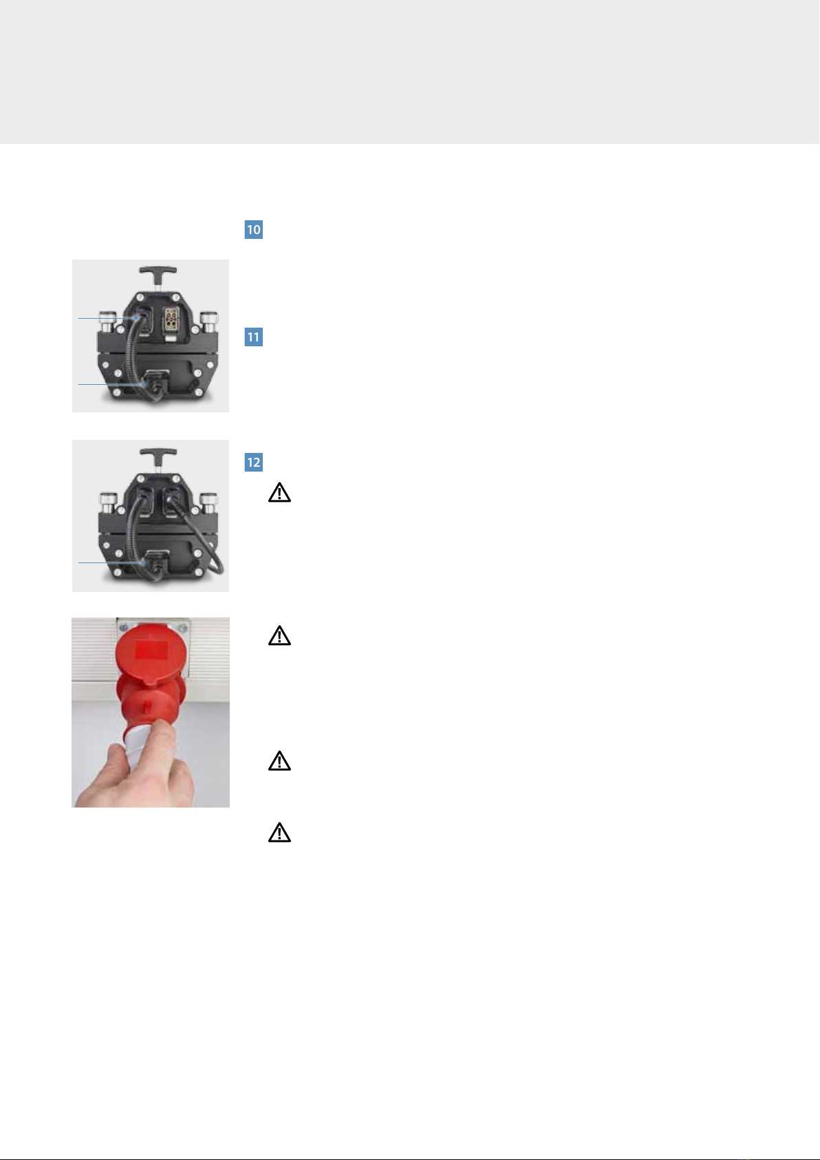
11
Connect umbilical power cable from top beam to bottom beam (Fig. 10)
a. Insert umbilical power cable connector into machine base umbilical cable connector.
b. Engage latch to lock plug in place. Forgetting to latch plug can result in intermittent
power supply to press base controls.
12
Connect power cord to press (Fig . 11)
Warning
It is extremely important that the power cord is attached to the press first and then to
the wall receptacle. Reversing these procedures can put personnel at risk of electrocu-
tion and may cause a damaging electrical arc.
a. Insert power cable connector to the machine base power outlet.
b. Engage latch to lock plug in place. Forgetting to lock plug can result in intermittent
power supply to the press.
Danger
c. Double check to ensure the voltage and receptacle is appropriate for the power
cable you are using. Incorrect, excessive power voltage can cause serious damage to
press and also present physical danger (i.e. 460 volt outlet feeding into a 230 volt
cable could cause a short circuit and/or fire).
d. Next, insert power cable plug into the appropriate wall receptacle. (Fig. 12)
Important
Only plug power cord into wall receptacle after power cord has been attached to the
tool.
Danger
e. User wiring of electrical plug to bare power cable end or hard wiring cable to junc-
tion box must be in accordance with the ‘Wiring diagram of power supply cable’
on page 20. Ensure proper cable diagram is used for cable being wired. Ensure the
correct plug is used. Only qualified personnel should perform this activity.
The heating press has 3 controllers:
1. The temperature controllers are located on the top beam.
a. Programming:
Splice temperature (max 200 °C/392°F), splice dwell time, cool down temperature.
2. The pressure controller is located on the bottom beam and controls the pressure up
to 2.5 bars/36.3 psi.
Fig. 10
Fig. 11
Fig. 12
SAFE OPERATION
Latch
Latch
Latch

13
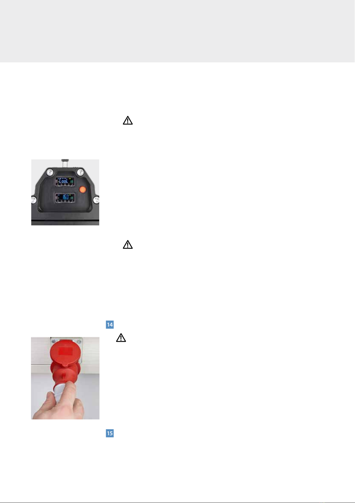
13
Configuration of the parameters
The Blizzard press has 2 digital controls, a pressure switch and an air bleeder. With all
these elements all the parameters of the process may be set. (Fig. 13)
a. Bottom digital controller
Controls: –Jointtemperatureandthecorrespondingdwelltime.
–Steppedtemperatureandthecorrespondingdwelltime.
–Coolingtemperature.
– Onthemainscreen(Fig.14),displaynº1showstheroomtemperature.Display
nº2showsthejointtemperature(preset173°C)Tochangethetemperaturepush
to increase the temperature, to lower it, and to modify the digit.
– Pushing weenterto“LAdJ”screen.If ispushed,“SP-0”willshowup.This
parameter shows the stepped temperature.
– Pushingagain “SoAK”showsup.Thisparameterrepresentsthedwelltime
(preset 240 seconds), corresponding to the joint temperature programmed in the
main screen. Therefore, push to increase the time, to lower it and to
modify the digit.
– Pushingagain thescreen“W6o-N”showsup.Thisparameterrepresentsthe
dwell time of the stepped temperature. To go back to the main screen push
On the main screen, if ispushed,“AL-1”willshowup.Thisparameterrepre-
sents the temperature cooling stops (preset 70°C).
b. Top digital controller
Controls: –Jointtemperature.
–Steppedtemperatureanddwelltime.
– Parametersareenteredinthesamewayasinthebottomdigitalcontrolsystem.
The only values that are not entered in this one are the joint temperature and the
coolingtemperature.Forinstance,“SoAK”and“AL-1”willnotshowup.
c. Pressure switch
Select the requiered pressure as well as the acceptable minimum pressure to
restart the compressor if there is any loss of air. (Forbo recommends to select
-0.2 bar), than the maximum one). When the press is connected to the mains,
the pressure shown is the actual one, that is 0 bar if it is not activated.
– Press“SET”key(shortpress)toaccesstoOUT1(on).Then,selectthemaximum
working pressure + o– (max. 2.5 bar). (Fig. 15)
– Pressagain“SET”(shortpress),toaccessOUT1(off).Select+ o– , to set
the pressure the compressor will turn on again to reach the maximum working
pressure previously set. This value shall be 0.2 bar less than the working pressure.
Warning
Make sure that this value is 0.2 bar less than the working pressure.
On the contrary, pressure regulator can be damaged.
– Pressagain“SET”(longpressforaround3seconds),andthemainscreenappears
again, showing the current pressure.
Fig. 15
Start button
Timer
Top
controller
Bottom
conroller
Air bleeder
button
Pressure switch
Fig. 13
Fig. 14
Function Key
Mode Key
Digit Key
Minus Key
Plus Key
Display nº 1
Display nº 2
14
SAFE OPERATION
The press includes a pressure relief device, that will hold 2.7 bar as the maximum
supplied pressure.
Warning
While in the main screen, avoid a long pressing of the SET key.
Ifyoudoit,thescreenwillshow“Unt”.Press“SET”(longpressforaround3seconds),
to return to the main screen.
d. Start button
When all the parameters and the belt have been prepared, start the process with the
button on the top frame, that will be lighted all along the process. (Fig. 16)
– Beforepressingstart,checkthatalltheboltsarefixed.
– Oncetheprocessisfinishedandthefansstopbecausethepresshasreached
thecooling temperature, a buzzer indicates that the process is finished. The buzzer
will not stop till it is deactivated.
e. Air bleeder
Once the process is finished, press the air bleeder to release the pressure.
Danger
Check that the start button is turned off, since if it is not, the air compressor will
supply pressure again, what may cause a physical danger an also a damage to the
press.
– Ifthepressisgoingtorepeataprocess,justpressthestartbutton,anditwill
automatically make another joint.
– Oncethepressureisreleased,dismantlecarefullythetoppartofthepress.
– Whenthepressisdisconnected,theparametersofthelastjointarestored.
14
Disconnect main power cable
Danger
a. It is critical to remove the power cord from the wall receptacle first. (Fig. 17)
b. Next, unlatch the cable connector from the machine base power inlet and gently
disconnect.
Following this sequence is critical for operator and bystander safety. Removing plug
from the wall receptacle first eliminates any current from flowing through the cable. If
this procedure is not performed first and the cable connector is removed initially, the
power cable remains energized and could cause serious and fatal shock if exposed to
water or other fluids.
15
Disconnect umbilical power cord from top beam
a. Unlatch cable connector.
b. Gently disconnect.
Fig. 16
Fig. 17

15
16
Remove top beam
a. Loosen all four press connector bolts.
b. Lift top beam off and place beam on side; do not place beam with platens facing
downward in contact with a surface.
Caution
Platen surfaces may be hot.
c. Remove top silicone pad and inspect splice. Elements of a properly installed endless
splice include:
– LimitedbutconsistentflowofPVC/Urethanematerialthroughthesplice.
–
Proper bonding, especially at the tips of the fingers. ‘Pin Holes’ should not be present
at finger tips.
– Bendingofthesplicejointshouldnotcreateanyseparationatthefingeredges.
– Noscorchingofthebeltcoverorbottomplyshouldbeevident.
17
Packing press in flight case
a. Reassemble top beam onto press, tighten all four press connector bolts, and install
clamp bars on press.
b. Carefully place press in flight case.
c. Close case and engage the locking latches.
18
Maintenance
a. The reading and the application of the advises of this handbook, besides the right
usage of the Blizzard, are the primary premises for the right maintenance and the
conservation of Forbo Siegling presses.
b. Forbo Siegling suggest a visual checking of all the system each time working with
Blizzard, pressure indicators and electrical connections. The usage of the products is
third people responsibility. Forbo Siegling only suggests in this handbook the right
procedures for the people and the equipment safety.
19
Solution to problems
Symptom Possible solution
No electric inlet Check the connection to mains
No electric inlet Check (only technicians) fuses, thermometers
and contactors in the control box.
No pressure Check pneumatic connections, and compressor.
Wrongly joining Check that the belt is centred in the plate.
Wrongly joining The parameters are not right. Check them and
try again to reach the perfect joining to each belt.
Thermometer shows. S.ERR The connection with the probe
16
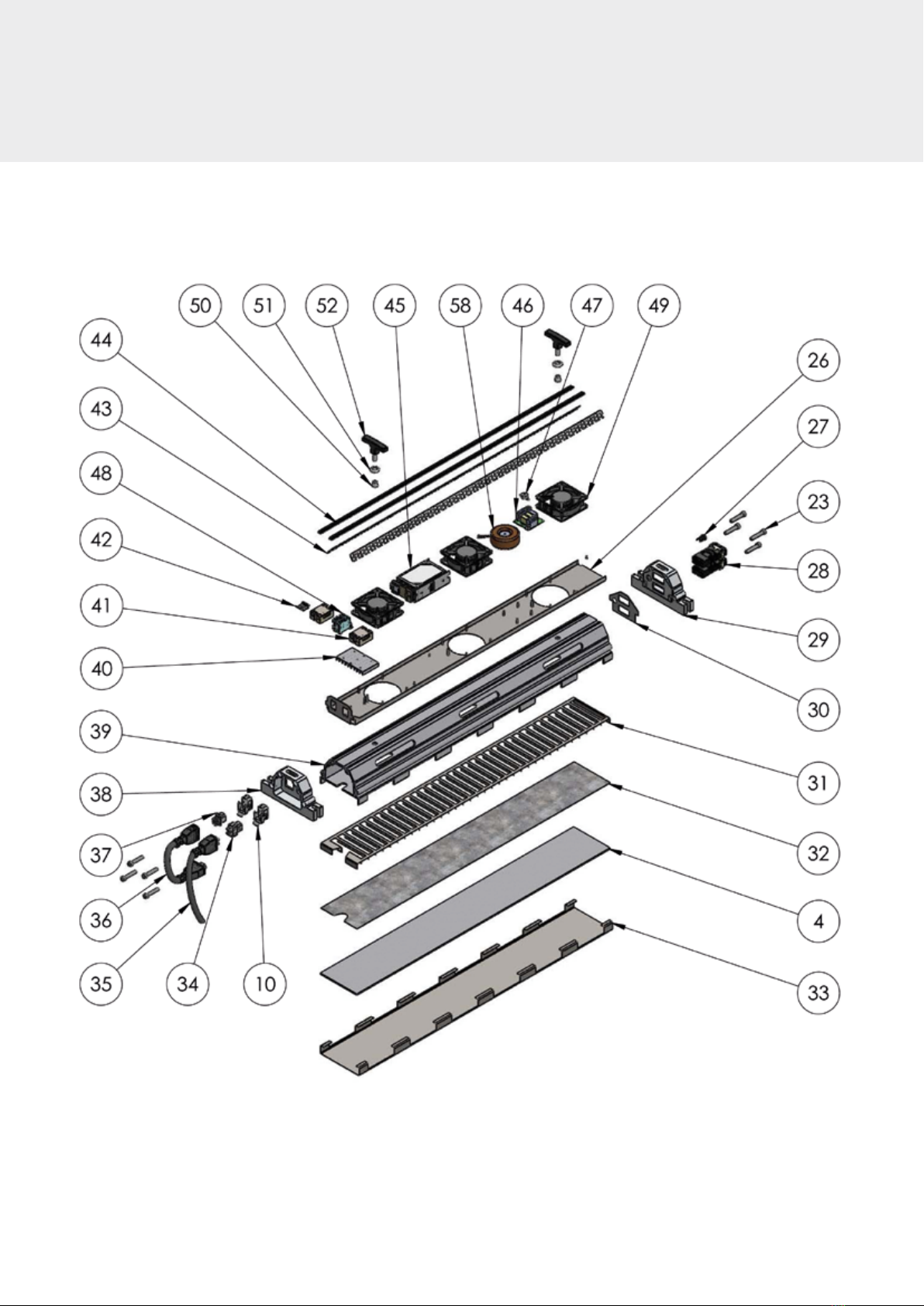
PLANS AND SCHEMES
Components of top frame

17
Components of bottom frame

18
PLANS AND SCHEMES
Components of the connections
Connection top E. – Bottom E. – Part Nº 36
Connection to the mains-part nº 35

19
List of components
Item no. Description code Qty.
11 Electrical connection base hanq
8 male with pins 1
37 Electrical connection base hanq
8 female with pins 1
53 Casing 3
54 Fitting 3
55 Electrical hose top-bottom
connection 1
56 Electrical connection base hanq
4 female with pins 1
57 Electrical hose three phase
connection 1
Item no. Description code Qty.
4 Resistance 1
10 Base connection 2
23 Screw DIN 912 M10x50 8
26 Top instrument carrier tray 1
27 Start buttom 1
28 Digital unit 2
29 Thermometers top front 1
30 Thermometers top instrument carrier 1
31 Top cooling grille 1
32 Plate 1
33 Top platen 1
34 Base inner piece 1
35 Main connection 1
36 Conexión superior-inferior 1
37 Jumperconnection 1
38 Bases top front 1
39 Top frame 1
40 Relay holder 1
41 Relay 2
42 Carril 1
43 Perforated plate 2
44 Nonslip rubber 2
45 Power source 1
46 Digital plate 1
47 Buzzer 1
48 Borna s=4 4
49 Fan A441352 3
50 Part 1 handle 2
51 Part 2 handle 2
52 Handle 2
58 Transformer 150 VA 1
Item no. Description code Qty.
1 Belt clamps bolt 4
2 Belt clamps 2
3 Bottomplaten 1
4 Resistance 1
5 Plate epoxy 1
6 Wood 1
7 Silicone bag 1
8 Bottom frame 1
9 Base bottom instrument carrier 1
10 Base connection 1
11 Base inner piece 1
12 Base bottom front 1
13 Bolt pin 4
14 Bottom instrument carrier tray 1
15 Nonslip rubber 2
16 Carril 1
17 Pressure 1
18 Compressor 1
19 Relay 1
20 Pressure regulator 1
21 Valve 1
22 Bottom main switch instrument carrier 1
23 Screw DIN 912 M10x50 8
24 Pressure switch bottom front 1
25 Bolt nut M12 4
Components of top frame Components of bottom frame
Components of the connections

20
European and UK cable
WIRING DIAGRAM OF THE
POWER SUPPLY CABLES
mono phase 230 V
three phase 230 V III
three phase 400 V III
three phase 400 V III + N + T
greygrey
brown
black
black
blue
blue
black
blue
blue
brown
black
greygrey
brown
black
brown
black
greygrey
brown
black
brown
black
GROUND
GROUND
GROUND
GROUND
Other manuals for siegling blizzard HP 160/400 AIR
1
This manual suits for next models
5
Table of contents
Languages:
Other Forbo Power Tools manuals


Popular Power Tools manuals by other brands


Shindaiwa
Shindaiwa M242/EVC Owner's/operator's manual

Josef Kihlberg
Josef Kihlberg JK24-690 Repair instructions

Surtek
Surtek TB572A User manual and warranty

Atlas Copco
Atlas Copco LH 11 Safety and operating instructions

CHESTER
CHESTER 836 TURRET MILL Operation manual

Fox
Fox F23-730 PLUS Assembly and operating manual