third coast equipment SP3410 User manual

Operator’s Manual
Single-Direction Vibratory Plate Compactor
SP3410 SP5013 SP4518
thirdcoastequipment.com

©2023 by Third Coast Equipment, Inc. All rights reserved.
All trademarks referenced in this manual are the property of their respective owners.
No portion of this manual may be reproduced without written permission from Third Coast
Equipment, Inc.
To reduce the risk of injury, all operators and maintenance personnel must read and understand
their machine’s instruction manual in full before operating, changing accessories, or performing
maintenance on that machine.
CONTENTS
Introduction 1
Applications 1
Safety Labeling 2
Hazard & Notice Iconography 2
Machine Label Locations 2
Machine Labels 3
Hazards & Risks 4
California Proposition 65 Warning 4
General Hazards & Risks 4
Transportation Hazards 4
Mechanical Hazards 5
Fire, Explosion & Thermal Hazards 5
Chemical Hazards 5
Noise Hazards 6
Personal Protective Equipment & Human Health Hazards 6
Additional Hazards 6
Operation 7
Steps before First Use 7
Daily Pre-Operation Inspection 7
Starting the Engine 7
Operating the Plate Compactor (Either Engine) 8
Using the Water Tank 9
Powering off the Plate Compactor 9
Emergency Shutdown Procedure 9
Tips for Proper Compaction 10
Extended Storage 11
Lifting & Transportation 11
Care & Preventative Maintenance 12
Machine Inspection Intervals 12
Engine Inspection & Maintenance Tables 13
Tightening Torque Tables 14
Specifications 15
Machine Specifications 15
Weight & Dimensions Reference Diagrams 15
Engine Specifications 16
Troubleshooting 17
Warranty 19

INTRODUCTION
Thank you for your purchase of this Third Coast Equipment, Inc. (“Third Coast”) single-direction
vibratory plate compactor. Please read this operator’s manual in its entirety prior to using your
new machine. This manual provides information pertaining to the safe use, proper operation,
and routine maintenance of this machine. All operators and maintenance personnel must read
and understand this manual in full before operating, changing accessories, or performing
maintenance on this machine.
This manual is written for Third Coast machines in production at the time of publication, and Third
Coast reserves the right to change any portion of this manual at any time without notice to reflect
any changes to current production machine configurations or updates to regulatory compliance
or for any other reason deemed appropriate by Third Coast.
The latest revision of this manual can be obtained by visiting us online at:
thirdcoastequipment.com
APPLICATIONS
Compaction is an essential step in construction; proper ground preparation is critically important
in setting a base for any structure, whether that structure be a road; residential, commercial or
industrial building; footing or pier; retaining wall; deck; or even a simple concrete sidewalk.
Any time earth is disturbed, whether through trenching, digging, excavation, or addition of gravel
substrates, it must be compacted before building commences.
Proper compaction ensures the ground is prepared to handle the weight of the structure above
it by increasing the packing factor of ground solids, eliminating unnecessary air, and reducing
compressibility. Proper mechanical compaction reduces the chances that the ground will shift or
further compress, thereby increasing the load capacity of that ground, reducing the risk of frost
heave, and increasing structural stability of the improvements above it.
Single-direction plate compactors feature a heavy-duty cast iron baseplate that vibrates under
high frequency to consolidate the earth or asphalt beneath it. An eccentric weight in the plate
exciter causes the machine to automatically travel in the forward direction; the operator needs
only to guide the compactor across the ground as it compacts the earth.
Single-direction plate compactors are ideal for:
Compacting granular & mixed soils
Gravel/aggregate compaction
Asphalt compaction & smoothing
Paver stone installation
Utility & trench compaction
SOIL COMPACTION
1

SAFETY LABELING
HAZARD & NOTICE ICONOGRAPHY
Third Coast machines use International Standardization Organization (ISO) compliant
iconographic labeling to depict and differentiate this machine’s dangers, warnings, and cautions
(collectively referred to as “hazards”) as well as to provide non-hazard related notices.
Indicates information not related to machine hazards, including tips for improved
operation or maintenance.
Indicates a hazard that could lead to minor or moderate injury if not avoided.
Indicates a hazard that could lead to serious injury or death if not avoided.
Indicates a hazard that will lead to serious injury or death if not avoided.
The one ISO label exception is the California Proposition 65 label, which per the California Office
of Environmental Health Hazard Assessment (OEHHA) requirement is a yellow warning triangle.
All possible hazardous situations cannot be covered in any operator’s manual. Care must be
exercised by everyone using, maintaining, or working on or near this equipment. If you are ever
in doubt of how to safely operate or service this equipment, cease operation immediately and
contact Third Coast or any Third Coast authorized dealer for assistance.
MACHINE LABEL LOCATIONS
The following labels are included on this Third Coast machine and must be maintained as part
of the machine. Any label that becomes illegible through operation, wear & tear, or for any other
reason must be replaced before the machine is operated, transported, or serviced.
MACHINE LABELS
The following hazard, notice, and informational labels are included on this Third Coast machine
and must be understood by all operators prior to operating this equipment.
LABEL INTERPRETATION
NAMEPLATE: The nameplate contains
important information about the model,
weight, gross horsepower, manufacturer, and
other machine-specific information.
OPERATION: This label depicts startup and
shutdown procedure, provides a caution to
read this manual, a warning to wear proper
personal protective equipment, and a danger
due to the emission of carbon monoxide.
CARBON MONOXIDE: This label identifies the
dangers of carbon monoxide emissions from
the engine.
GASOLINE: This equipment runs on gasoline
only, with a maximum ethanol content of 10%.
HOT SURFACE: This label warns of the risk of
burning from contact with a hot surface.
LIFTING: This label identifies the proper
lifting point for transport of this equipment
and cautions the user of the hazards
associated with improper lifting practices.
PROP 65: This label identifies the hazard
related to the emission of gasoline engine
exhaust, as required by CA OEHHA.
2 3

HAZARDS & RISKS
CALIFORNIA PROPOSITION 65 WARNING
Use of this product may expose you to certain chemicals, including gasoline
engine exhaust, which are known to the State of California to cause cancer.
GENERAL HAZARDS & RISKS
General hazards are those that do not fall under a specific hazard classification,
or that relate to multiple hazard classifications.
Ensure all operators read and understand the operator’s manual prior to using this machine.
Never operate or allow anyone else to operate this machine without understanding the
operational and safety controls of this machine. Even after reading the manual, new operators
should receive instruction from an experienced operator.
Never leave a machine operating while unattended.
Use only accessories recommended by Third Coast. Any non-approved accessories may lead to
operator injury or machine damage.
Inspect this machine before every operation and at the required intervals listed in the “Care &
Preventative Maintenance” section.
Clean the machine during and after each use to ensure all safety labels remain legible. Replace
any illegible safety labels before continued operation.
Serious injury can result from improper or careless use of this machine.
Keep this machine out of the reach of children at all times, including when not in use.
TRANSPORTATION HAZARDS
Failure to adequately secure this machine while transporting and failure to lift
with proper form can result in damage to the equipment or injury or death.
Inspect all lifting hardware (both on this machine and all ancillary lifting equipment) prior to
lifting this machine.
Never lift this machine while it is operating.
Ensure the fuel cap is tight prior to lifting or transporting this machine.
Only lift this machine with proper load-rated straps or slings rated for the weight and
application.
Never stand or work under a lifted machine.
This machine is heavy. Lift using auxiliary equipment whenever possible. If you must lift
manually, always have help from additional persons, ensure a clear path to your destination,
ensure stable and clear ground, maintain a good grip on the machine, and lift with proper
ergonomic form.
MECHANICAL HAZARDS
Certain mechanical hazards are inherit in operating this machine due to the
weight, operation, travel, and vibration of this machine. Disregarding these warnings can lead to
serious injury.
Do not operate this machine unless all protective guards are in place.
Keep hands and feet clear of rotating and moving parts.
Ensure the engine operation switch is in the OFF position and the spark plug ignition lead is
disconnected before removing the guards or making adjustments or repairs.
Ensure both the machine and the operator are set up on stable ground while in operation or
service.
Do not leave this machine unattended while in operation.
When working in trenches, ensure the trench walls are stable and will not collapse due to the
action of the vibration prior to commencing compaction. Trench shoring should be utilized.
Ensure the area to be compacted does not contain any live electrical cables, gas, water, or
communication services that may be damaged by the vibration.
Never stand on the unit while it is operating.
Do not increase the governed no-load motor speed above 3,600 rpm; personal injury and
damage to the machine may result.
All machine and engine repairs should be conducted by a certified servicing dealership.
FIRE, EXPLOSION & THERMAL HAZARDS
Internal combustion engines contain flammable gasoline and generate spark and
heat that pose certain hazards.
Gasoline is extremely flammable and explosive under certain conditions.
Ensure gasoline is only stored in an approved storage container.
Do not refuel while the engine is operating or hot.
Do not refuel in the vicinity of sparks or open flame.
Do not refuel in confined spaces. Gasoline vapors may concentrate and ignite.
Only fuel this machine on the ground. Do not fuel in truck beds or other areas where static
electricity may be present.
Do not overfill the fuel tank.
Ensure the fuel cap is securely fitted after refueling.
Avoid spilling gasoline when refilling; spilled gasoline or gasoline vapors may ignite. If spillage
occurs, clean the area per local environmental regulations prior to resuming operation.
Avoid contact with the engine and muffler while this machine is running or while hot. Extreme
heat may cause severe burns.
Do not operate this product in enclosed spaces or modify it in any way that reduces engine
cooling.
CHEMICAL HAZARDS
Certain chemical hazards exist due to the presence of gasoline, grease, oil, and
other chemicals presented by the combustion process including carbon monoxide, a colorless,
odorless gas that can cause death if inhaled. Failure to follow the below instructions may lead to
severe injury or death.
Do not operate in a confined space or without adequate ventilation. Carbon monoxide exhaust
4 5

gases from internal combustion engine driven equipment can cause death in confined spaces.
Do not refuel this machine in confined spaces. Gasoline vapors may be hazardous to your
health, and concentrated gasoline vapors may cause an explosive atmosphere.
Any fluids spilled from the machine, whether flammable or not, must be cleaned up in a manner
consistent with all local environmental regulations.
Always use approved fluids when maintaining or servicing this machine. Improper fluids may
lead to poor performance or failures of the machine and may create a hazardous situation for the
operator or bystanders. Dispose of all fluids properly in accordance with local regulations.
NOISE HAZARDS
This equipment exceeds the Occupational Safety & Health Administration (“OSHA”)
safe noise levels that can cause temporary or permanent hearing loss.
Wear an approved hearing protection device while operating this machine to limit noise
exposure as required by OSHA regulations.
Bystanders may also require hearing protection, depending on their distance to the machine.
Always be visually aware of your surroundings. While operating this machine, you may not hear
other auditory warnings from nearby equipment. Heightened awareness is required.
PERSONAL PROTECTIVE EQUIPMENT & HUMAN HEALTH HAZARDS
Proper personal protective equipment and operating practices are important to
minimize the inherent hazards that this machine presents.
Always wear proper protective clothing when operating this equipment, including hearing
protection, respiratory protection, shatterproof eye protection, safety-toe boots, and other
personal protective equipment (“PPE”) as required by OSHA or local regulations.
Exercise care when operating this unit. Exposure to vibration or repetitive work actions may be
harmful to the hands and arms.
Slip/trip/fall hazards are a major cause of serious injury and death. Beware of uneven or
slippery work surfaces.
Exercise care when working in the vicinity of open trenches, holes, or excavations.
Never operate this equipment under the influence of drugs or alcohol. This includes
prescription drugs without your doctor’s consent.
Never operate this equipment when you are not feeling well.
ADDITIONAL HAZARDS
It is not possible to document all of the scenarios that could result from misuse
of this machine, and proper operation and jobsite safety best practices should always be followed
to minimize the occurrence and severity of all hazards.
Only use this machine for its intended application.
Always have an emergency preparedness plan, and practice it often.
Always have a first aid kit and fire extinguisher on the jobsite. Ensure the fire extinguisher is
rated for the applications, including fires caused by the combustion of gasoline.
Do not work alone; always ensure someone else is on the jobsite with you.
Know your jobsite address so you can give it to first responders in an emergency.
OPERATION
STEPS BEFORE FIRST USE
To get you up and running faster, pre-delivery service is completed at Third Coast’s warehouse
prior to shipping your machine to you. This consists of filling all fluids to proper levels (except
for gasoline), torquing all fasteners to the proper operational torque, and validating machine
operation and performance. Upon receipt of your machine, you only need to fill the fuel tank and
perform a visual inspection to confirm nothing has been damaged in transit.
DAILY PRE-OPERATION INSPECTION
The following inspections must be completed prior to each daily use of the plate compactor, and
again after every four hours of machine operation.
Visually inspect the machine for signs of damage. Remove any dirt, debris, or material that may
have accumulated from prior use.
Clear any dust accumulation from the air filter, carburetor, and engine cooling fins.
Check all hardware to ensure proper tightness. See the “Care & Preventive Maintenance”
section for proper fastener torque.
Check the engine oil level and refill as needed.
Check for fuel and oil leaks and repair as needed.
Refuel your plate compactor.
STARTING THE ENGINE
This plate compactor comes either with a Vanguard or Honda engine. Starting for each engine
model is as follows:
VANGUARD ENGINE START-UP
Position the throttle lever to idle speed position, indicated by a turtle icon ( ).
If starting a cold engine, position the choke lever in the CLOSED position indicated by the full
choke icon ( ). A warm engine may only need partial or no choke ( ).
Gently pull the recoil starter until mild resistance is felt, then pull sharply to turn over the
engine. Allow the recoil starter to gently return to the retracted position.
Repeat pulling the recoil starter as needed
until the engine is running.
As the engine warms up, begin moving the
choke slowly to the OPEN position ( ). If the
engine stalls while doing this, repeat the entire
startup process and proceed more slowly in
transitioning the choke from CLOSED to OPEN.
Allow the engine a few minutes to warm up in
the idle position before starting compaction.
To start compaction, move the throttle lever
to the FAST position, indicated by the icon of
a rabbit ( ). See the “Operating the Plate
Compactor” section. VANGUARD ENGINE OPERATION
THROTTLE LEVER
CHOKE LEVER
6 7

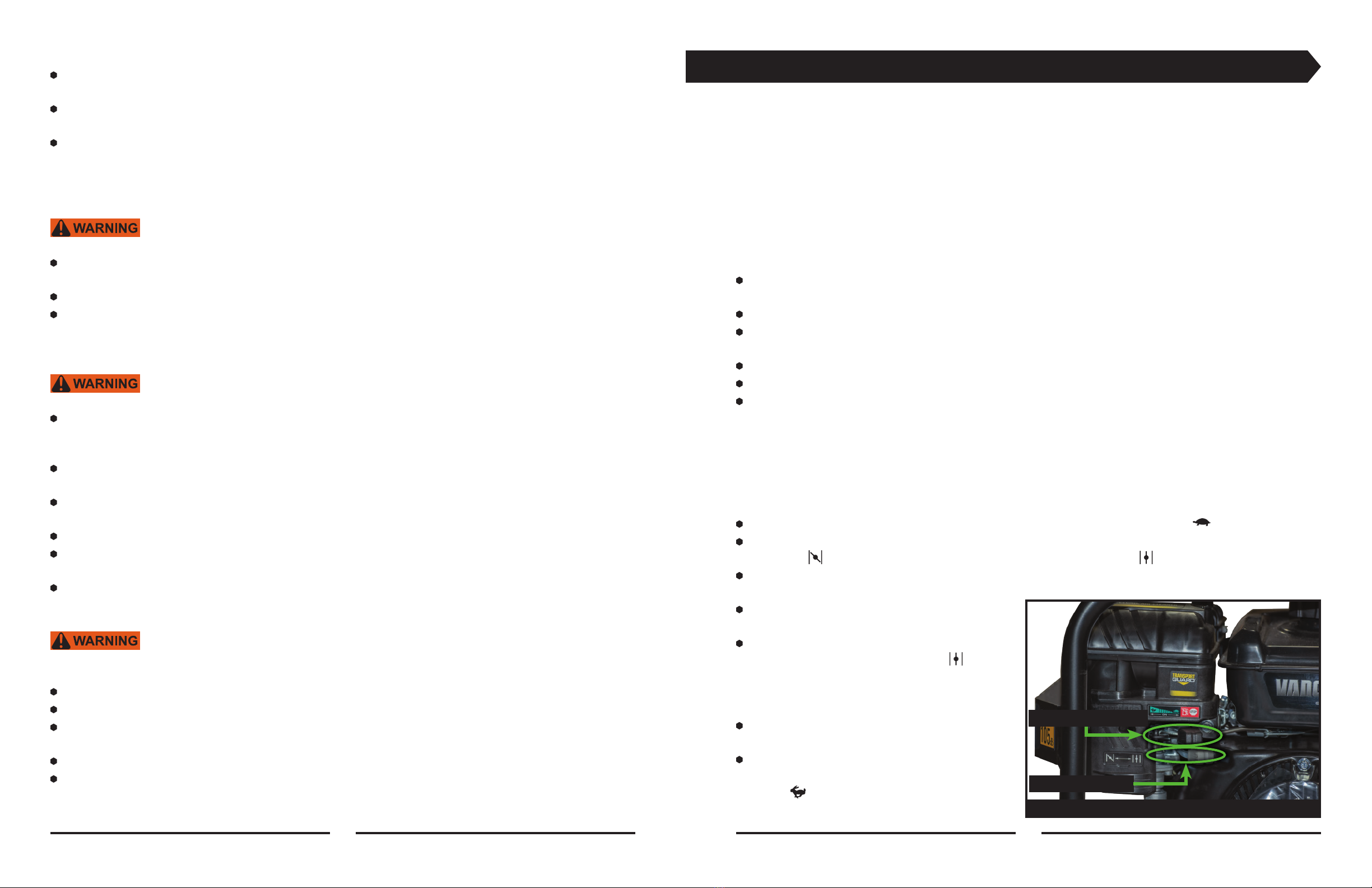
HONDA ENGINE STARTUP
Position the On/Off lever and fuel valve to the ON
position, and the throttle lever to the idle position ( ).
If starting a cold engine, position the choke lever in the
CLOSED position indicated by the full choke icon ( ). A
warm engine may only need partial or no choke ( ).
Gently pull the recoil starter until mild resistance is
felt, then pull sharply to turn over the engine. Allow the
recoil starter to gently return to the retracted position.
Repeat pulling the recoil starter as needed until the
engine is running.
As the engine warms up, begin moving the choke lever
slowly to the OPEN position ( ). If the engine stalls,
repeat the entire startup process and proceed more
slowly in transitioning the choke from CLOSED to OPEN.
Allow the engine a few minutes to warm up in the idle
position before starting compaction.
To start compaction, move the throttle lever to the
FAST position, indicated by the icon of a rabbit ( ).
OPERATING THE PLATE COMPACTOR (EITHER ENGINE)
To begin the compaction process, set the throttle
to the FAST position ( ). The plate compactor will begin to travel forwards. Do not force the
plate compactor forward or attempt to retard its motion; its travel speed is pre-set for optimal
compaction.
Do not operate this machine with the throttle lever set to anything other than IDLE ( ) or FAST
( ); engine speeds in between idle or full throttle will cause premature wear to the clutch and
belts and provide inadequate compaction; such wear and tear is misuse and is not covered under
warranty.
Keep both hands on the plate compactor handle as it travels down your compaction surface,
and use gentle pressure on the handle to steer it as required.
To briefly pause compaction, set the throttle to the IDLE ( )position. Do not attempt to hold a
moving machine in a fixed position. Do not leave an idling compactor unattended. If the machine
will be unattended, follow the shutdown instructions listed under the “Powering off the Plate
Compactor” section.
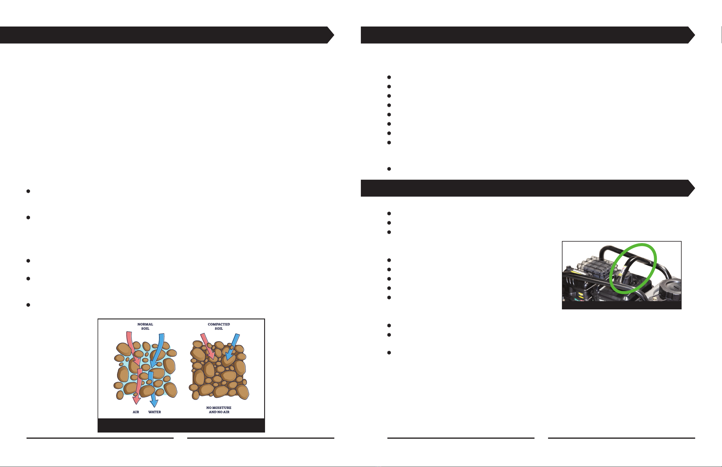
Do not over-compact your soil. Not only is over-compaction a bad practice for jobsite
preparation, leading to a weaker substrate, but over-compaction may also have damaging effects
on your compactor, including increased wear and tear, as well as transmit a high hand-arm
vibration to the operator.
For useful suggestions on how to achieve the ideal level of soil compaction, see the “Tips for
Proper Compaction” section. If you are ever in doubt of how to prepare your surface for proper
compaction, consult your jobsite engineer for guidance.
HONDA ENGINE OPERATION (1)
HONDA ENGINE OPERATION (2)
ON/OFF LEVER
THROTTLE
LEVER
CHOKE
LEVER
FUEL
VALVE
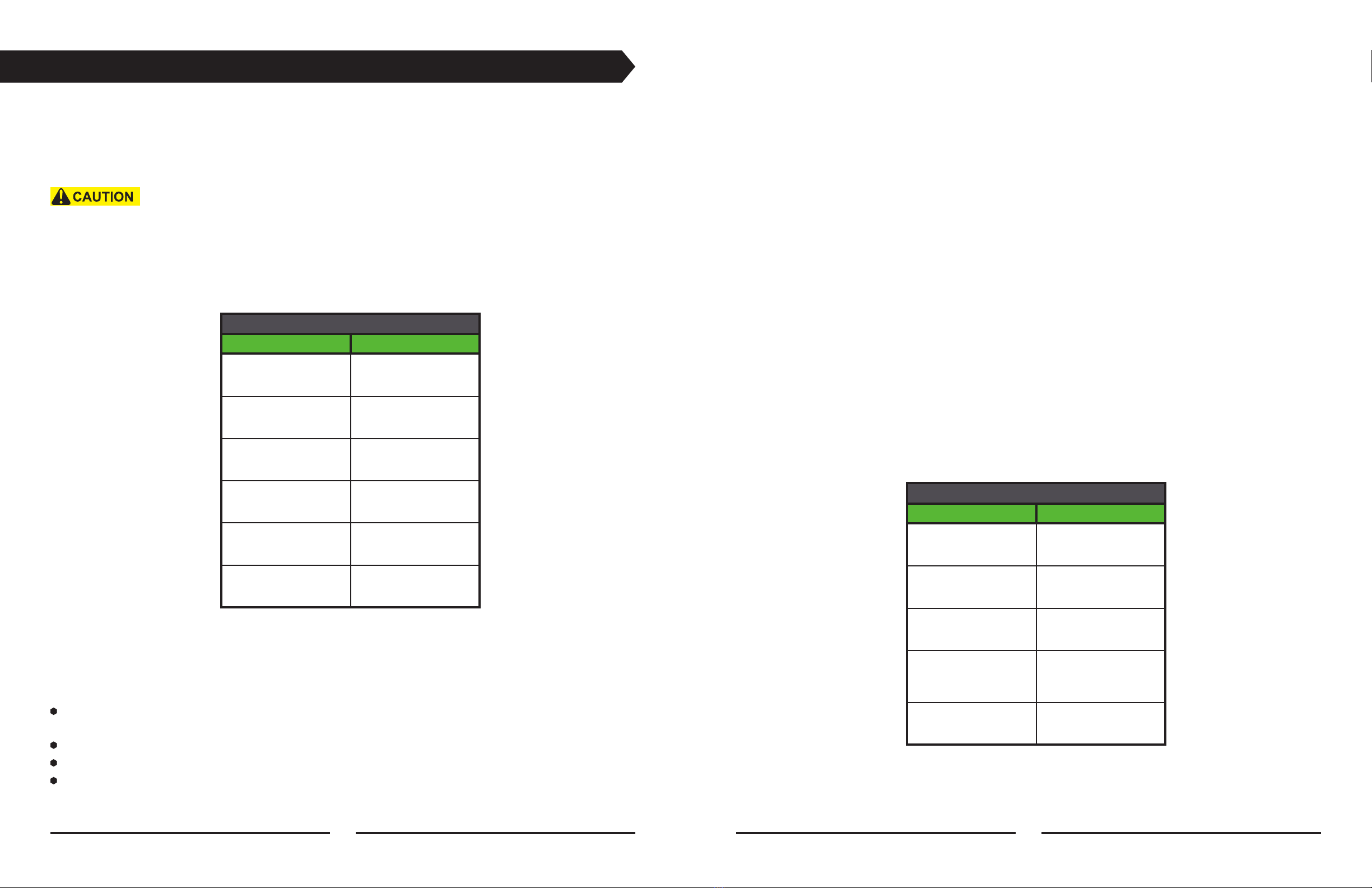
USING THE WATER TANK
This single-direction plate compactor features an integrated water tank to distribute water under
the plate compactor. While compacting soil, water under the plate compactor can help with
jobsite dust control in dry climates. When finishing asphalt, adding water under the compactor
is imperative to improve surface finish of the asphalt and to prevent asphalt from sticking to the
bottom of the compactor.
The water tank can be filled by inserting a fill hose through the
slotted cap. The cap will help retain the hose while filling.
Alternatively, the cap can be removed when pouring water in.
To start or adjust the flow of water, open the water valve.
Always use clean water from a known source. Debris or hard
water will clog the distribution bar, reducing performance of the
water system. The distribution bar can be removed for
cleaning; frequent cleaning should be a point of routine
maintenance.
The water tank can be removed by lifting the tank off the
compactor. Depending on the model, the hose clamp holding the
water hose to the water distribution bar may need to be removed
to fully remove the water tank.
POWERING OFF THE PLATE COMPACTOR
To shut down the plate compactor during the workday, when further work is expected within 24
hours, position the throttle lever in the STOP ( ) position (Vanguard) or position the On/Off lever
to the OFF position (Honda).
To shut down the Honda engine equipped plate compactor and prepare it for short-term
storage (between 1 day and 30 days), position the throttle lever to the IDLE ( ) position while
the engine is still running, then position the fuel On/Off lever to the OFF position. Allow the
engine to consume the fuel in the carburetor until the engine shuts off, then turn the engine On/
Off switch to the OFF position. This procedure allows the carburetor to empty its fuel, which
reduces the chance for gumming or plugging of the carburetor.
For the Vanguard engine, there is no special power-down sequence for short-term (1 to 30 day)
storage. Follow the standard shutdown procedure listed above.
When preparing plate compactors of either engine type for short-term storage, it is always
recommended to treat the fuel with a fuel stabilizer to help ensure it is ready for its next
operation.
To prepare the plate compactor with either engine for extended storage (more than 30 days),
see the “Extended Storage” section.
EMERGENCY SHUTDOWN PROCEDURE
HONDA ENGINE: To shut down the Honda engine equipped plate compactor in an emergency
situation, position the On/Off switch to the OFF position.
VANGUARD ENGINE: To shut down the Vanguard engine equipped plate compactor in an
emergency situation, position the throttle lever to the STOP ( ) position.
WATER VALVE
WATER TANK & SPRAY BAR
8 9

TIPS FOR PROPER COMPACTION
Proper compaction is extremely important in construction, as it eliminates extraneous air in the
substrate and reduces the transport of air and water, resulting in a more stable base with less
chance of shifting or settling. Builders can usually compensate for surfaces that are out of level,
but they cannot compensate for substrates that are poorly compacted; settling of improperly
compacted substrates will always cause defects in the improvements, whether a dip in a
driveway, a crack in a foundation, or a shift in a footing.
Your best resource regarding proper jobsite compaction is your jobsite engineer. If you have a
jobsite engineer, they will dictate the lift height (the thickness of each layer to be compacted) as
well as the number of passes required for each lift based on the local soil conditions and any
infill aggregate type. If you have a jobsite engineer, always follow their specification for proper
compaction.
If you do not have a jobsite engineer, you can ensure the best possible compaction with these
helpful rules of thumb:
Don’t overdo it. Cracking soil indicates over-compaction. Over-compaction can break down the
soil itself, resulting in a much weaker substrate than properly compacted soil. Over-compaction
can also cause premature wear and tear to your plate compactor, shortening its life.
As you gain experience with this machine, you will understand and interpret how the machine
feels as you start to compact, attain proper compaction, and when you are over-compacted. The
guidance of a more experienced operator can help you build this experience, but a general rule
of thumb is that over-compaction will result in erratic machine movements and excessive hand-
arm vibration.
Count your passes in each area and track your areas closely. Uniform compaction is equally
important as the right amount of compaction.
If in doubt of your lift requirements, a good rule of thumb is three passes over a lift of 6” to 12”
for typical soils. For very dry soils, reduce lift to 75% of the nominal. It is better to have a lower
lift and fewer passes than to try to compact too large a lift with more passes.
If in doubt of your local conditions, use a field test apparatus such as a dynamic cone test to
ensure your soil is properly compacted prior to building.
EXTENDED STORAGE
Following proper long-term storage procedures ensures the machine is ready to operate when
you return to it. The following procedure should always be performed when the machine will not
be in use for the next 30 days:
Drain the fuel tank completely.
Operate the plate compactor to consume any residual fuel in the fuel lines and carburetor.
Thoroughly clean the exterior of the machine with a damp rag, then dry it. Do not use solvents.
Check and repair any leaks and tighten any loose hardware prior to storage.
Check the engine oil, and top off if necessary.
Clean the fuel filter.
Clean or replace the air filter.
Remove the spark plug and pour 1-2cc (about a half-teaspoon) of engine oil into the spark plug
hole. Pull the recoil starter a few times to distribute this oil while the spark plug is removed.
Replace the spark plug.
Store the machine in a clean and dry indoor storage location.
LIFTING & TRANSPORTATION
PRIOR TO LIFTING OR TRANSPORTING YOUR MACHINE:
Power down the machine.
Ensure all hardware, including the fuel cap, is secure on the machine. Tighten any loose bolts.
Close the fuel valve.
TO LIFT THIS MACHINE:
Use a single-point lift bail rated for the weight.
Attach the lift bail only around the lift eye.
Lift straight upwards, never at an angle.
Never lift higher than necessary.
Never walk underneath the machine when lifted.
TO TRANSPORT THIS MACHINE:
For transporting short distances around the jobsite, use the optional wheel kit.
When transporting over the road, always tie down the machine using tie-down straps of
adequate strength for the weight of this machine.
Always use more than one strap to secure this machine.
LIFTING POINT
SOIL COMPACTION
10 11

CARE & PREVENTATIVE MAINTENANCE
Third Coast plate compactors are designed to provide years of trouble-free service, but as with
any high-vibration equipment, periodic maintenance is required to keep it running smoothly.
Maintenance is a normal part of ownership of any plate compactor and must be carried out
on-time per the prescribed intervals or as needed. Please note, this operator’s manual is not a
service guide. All service should be done by a qualified, trained service technician.
Inspection and other service should always be carried out on hard, level
ground with the engine shut down.
MACHINE INSPECTION INTERVALS
This plate compactor must be inspected, at a minimum, at the intervals described in “Table 1”
below. In tough operating environments, more frequent inspection is recommended.
TABLE 1: MACHINE INSPECTION
ITEM OPERATION HOURS
Basic Operation
Check
Every 4 hours or
every day
Full Visual
Inspection
Every 8 hours or
every day
Machine Control
Check
Every 8 hours or
every day
Exciter Oil Check Every 100 hours
V-Belt (Clutch)
Check
Every 200 hours
Exciter Oil
Replacement
Every 300 hours
BASIC OPERATION CHECK
Prior to each daily use of the equipment, and again after every four hours of operation, the
following inspection must be completed:
Visually inspect the machine for signs of damage. Remove any dirt, debris, or material that may
have accumulated from prior use.
Clear any dust accumulation from the air filter and carburetor.
Check all hardware to ensure proper tightness.
Check for fuel and oil leaks and repair as needed.
FULL VISUAL INSPECTION
At the start of each workday, or after each eight hours of machine operation, perform a full
visual inspection of the machine, looking for signs of visible damage to any component. Repair or
replace any defects found prior to operating the machine.
MACHINE CONTROL CHECK
At the start of each workday, or after each eight hours of machine operation, perform a full
inspection of all machine controls, including those on the engine. Confirm all cables, knobs, and
levers operate smoothly and through their full range of motion. Repair or replace any defects
found prior to operating the machine.
EXCITER OIL CHECK
After every 100 hours of machine operation, check the exciter oil and refill as required.
V-BELT/CLUTCH INSPECTION
After every 200 hours of machine operation, perform a visual inspection of the machine drive belt
and clutch. Repair or replace any defects found prior to operating the machine.
EXCITER OIL REPLACEMENT
After every 300 hours of machine operation, replace the exciter oil.
ENGINE INSPECTION & MAINTENANCE TABLES
To maximize the lifespan of your plate compactor’s engine, inspect and maintain it per the
schedule in “Table 2” below.
TABLE 2: ENGINE MAINTENANCE
ITEM OPERATION HOURS
Oil Leakage Every 8 hours or
daily
Oil Level
Replenishment
Every 8 hours or
daily
Loose or Missing
Hardware
Every 8 hours or
daily
Engine Oil
Replacement
After first 20 hours,
then every 100
hours
Air Cleaner Clean/
Replace
Every 50 hours
12 13

TIGHTENING TORQUE TABLES
The threaded fasteners on this machine are all right handed, coarse-thread, metric, Class 8.8 or
Class 12.9 fasteners.
All fasteners on this machine are marked by strength class and must be torqued to the proper
specification for that class. To identify whether a fastener is a Class 8.8 or Class 12.9 fastener,
check the identifying marks stamped on the head.
8.8
CLASS 8.8 FASTENER
12.9
CLASS 12.9 FASTENER
TABLE 3: TIGHTENING TORQUE FOR CLASS 8.8 FASTENERS, FT·LB
THREAD SIZE> M6 M8 M10 M12 M14 M16 M18 M20
TORQUE, FT·LB> 9 22 44 76 122 190 262 370
TORQUE, N·M> 12 30 60 103 165 257 355 501
TABLE 4: TIGHTENING TORQUE FOR CLASS 12.9 FASTENERS, N·M
THREAD SIZE> M6 M8 M10 M12 M14 M16 M18 M20
TORQUE, FT·LB> 16 38 75 131 209 326 451 636
TORQUE, N·M> 22 52 102 178 283 442 611 862
SPECIFICATIONS
MACHINE SPECIFICATIONS
TABLE 5: COMPACTOR SPECIFICATIONS
WEIGHT & DIMENSIONS SP3410 SP5013 SP4518
Operating Weight, lb 143 183 212
Base Plate Width, in (A) 14 20 22
Base Plate Length, in (B) 19.5 20.5 22
Machine Length, in (C) 25 28 27
Overall Length, in (D) 40 42 41
Machine Height, in (E) 22.5 21.5 24.5
Overall Height, in (F) 36.5 33.0 38.5
PERFORMANCE DATA SP3410 SP5013 SP4518
Baseplate Material Cast Iron Cast Iron Cast Iron
Centrifugal Force, lbf 2248 2923 4046
Vibration Frequency, vpm 4500 5500 5400
Travel Speed, ft/min 72 80 106
Drive Belt 1 x “A” Section V-Belt
Centrifugal Clutch Sealed, Grease Lubricated
Exciter Sealed, Oil Bath Lubricated
Exciter Oil Type SAE 30 or 10W-30 SAE 30 or 10W-30 SAE 30 or 10W-30
Exciter Oil Capacity 5.1 fl oz (150mL) 8.5fl oz (250mL) 8.5fl oz (250mL)
WEIGHT & DIMENSIONS REFERENCE DIAGRAMS
14 15

ENGINE SPECIFICATIONS
This machine is available with Honda GX160 or Vanguard 200 engine options:
TABLE 6: ENGINE SPECIFICATIONS
HONDA GX160 VANGUARD 200
Engine Manufacturer Honda Vanguard
Engine Model # GX160 12V3
Horsepower, Gross Not Published 6.5 HP
Horsepower, Net 4.8 HP Not Published
Operating Speed 3,600 rpm 3,600 rpm
Bore 68mm 68mm
Stroke 45mm 56mm
Displacement 163 cm³ 203 cm³
Compression Ratio 9:1 8.4:1
Lubrication Splash Splash
Engine Oil Type SAE 30 or 10W-30 SAE 30 or 10W-30
Engine Oil Capacity 20.3 fl oz (0.6L) 20 fl oz (0.59L)
Notice: Both compactor and engine specifications are subject to change at any time. The
specifications in the manual provided with your machine are accurate for your machine, but if
accessing this manual online please note the specifications may not match your machine.
SYMPTOM POSSIBLE CAUSE SOLUTION
Engine does not start,
but has spark. Ignition switch in Off “O” position (Honda
only). Turn switch to On “I” position.
Fuel valve in Off position (Honda only). Move fuel lever to the On position.
Engine throttle lever in Stop position
(Vanguard only). Move throttle lever to idle speed position.
Fuel level too low. Fill fuel tank.
Stale or old fuel. Confirm fuel is clear, fresh, and free of
water and contaminants. Replace fuel if
necessary.
Summer blend fuel used in temperatures
below 45ºF. Replace with winter blend fuel
(manufactured October 15 - April 15).
Oil level too low (Oil sensor will prevent
starting). Check oil level and refill.
Fuel system clogged. Clean fuel filter, fuel lines, carburetor
float needle valve, carburetor bowl, and
carburetor fuel nozzles, and try again.
Engine has no spark,
or has weak spark. Spark plug worn or damaged. Replace spark plug.
Poor connection between ignition wire
and spark plug. Check connection between ignition wire
and spark plug. Tighten or replace.
Damaged ignition kill switch (Honda
only). Check ignitions kill switch function and
replace if needed.
Worn or damaged ignition coil. Check for spark from ignition coil using
spark tester or inductive tachometer.
Replace if no spark present.
Engine difficult to start,
or will not remain
running at idle.
Clogged fuel system. Clean fuel filter, fuel lines, carburetor
float needle valve, carburetor bowl, and
carburetor fuel nozzles.
Stale or old fuel. Confirm fuel is clear, fresh, and free of
water and contaminants. Replace fuel if
necessary.
Summer blend fuel used in temperatures
below 45ºF. Replace with winter blend fuel
(manufactured October 15 - April 15).
Engine will not reach
full speed.
Choke lever is in ON position. Move choke lever to OFF position after
warming up the engine.
Stale or old fuel. Confirm fuel is clear, fresh, and free of
water and contaminants. Replace fuel if
necessary.
Dirty air filter. Inspect the air filter. Replace if
necessary.
Lack of exciter oil; this causes bearings
to swell and overload the engine.
Inspect exciter oil level. If low, replace
exciter bearings and exciter oil.
TROUBLESHOOTING
16 17

SYMPTOM POSSIBLE CAUSE SOLUTION
Engine shuts off after
operating for a short
period of time.
Fuel valve partially closed (Honda only). Move fuel lever to Open position.
Oil level too low. Low oil cutoff engaged. Check oil level. Refill if necessary.
Fuel system clogged. Clean fuel filter, fuel lines, carburetor
float needle valve, carburetor bowl, and
carburetor fuel nozzles, and try again.
Engine shuts off after
being operated for a
long period of time.
Winter blend fuel used in temperatures
>70ºF causing vapor lock.
Winter blend (manufactured October 15
- April 15) evaporates too easily. Replace
with summer blend fuel.
Fuel level too low. Fill fuel tank.
Oil level too low. Low oil cutoff engaged. Check oil level. Refill if necessary.
Engine operates
normally, but there is
no compaction.
Engine speed too low. Only compact at full throttle.
V-Belt loose. Check V-Belt tension. Proper tension is
1/4” - 3/8” deflection when pressing on
middle of belt.
Broken V-Belt. Replace V-Belt.
Failed or slipping clutch. Confirm clutch is engaging at full throttle.
Replace if not engaging.
Engine achieves full
RPM but vibration
impact or travel speed
seems low.
Ground is too wet and/or sticky,
especially when compacting clay soils.
Allow soil to partially dry before
resuming compaction.
Dirt/debris accumulation on bottom of
plate, especially common with heavy clay
soils.
Clean build up off of plate, allow ground
to partially dry if needed, and resume
compaction.
Slipping V-Belt due to loose tension. Check V-Belt tension. Proper tension is
1/4” - 3/8” deflection when pressing on
middle of belt.
Worn V-Belt. Check the belt condition and replace if
stretched or showing visible wear.
Slipping clutch. Confirm clutch is operating at the same
rotational speed as the engine. Replace
clutch if slipping.
Excessive handle
vibration.
Soil over compacted or too hard. Move machine to a compactable surface.
Loose main shockmount hardware. Torque shockmount hardware to proper
specification.
Loose handle hardware. Torque handle hardware to proper
specification.
Worn or damaged hand pivot
shockmounts.
Inspect rubber shockmounts on both
inside and outside of handle pivot point
for cracking or wear. Replace if needed.
Worn or damaged main shockmounts. Inspect rubber shockmounts between
baseplate and engine mounting plate for
cracking or wear. Replace if needed.
SYMPTOM POSSIBLE CAUSE SOLUTION
Water system fails to
deliver water.
Low water level. Refill water tank.
Clogged water system. Check water tank, hose and distribution
bars for build up. Clean if necessary.
Loose water valve lever. Check the water valve lever nut. Tighten
if necessary.
Bad water valve. Remove the water valve and inspect for
proper function. Replace if necessary.
Water system delivers
too little water.
Clogged water system. Check water tank, hose and distribution
bars for build up. Clean if necessary.
Bad water valve. Remove the water valve and inspect for
proper function. Replace if necessary.
Loose water valve lever. Check the water valve lever nut and
tighten if necessary.
Uneven water
distribution across
water distribution bar.
Clogged water system. Check water tank, hose, and distribution
bars for build up. Clean if necessary.
Water valve not in fully open position. Open water valve more to ensure uniform
distribution.
WARRANTY
WARRANTY
year
5
Third Coast Equipment stands behind all of its products with a best in class
warranty, including:
Five-year warranty on spare parts
Four-year warranty on Vanguard engines
Three-year warranty on Honda engines
Two-year warranty on labor
This limited warranty contains certain exclusions and limitations and is
restricted to repair or replacement of the machine or affected parts only.
Other exclusions may apply.
To view the full Third Coast Equipment warranty policy, visit:
https://thirdcoastequipment.com/warranty-policy
18 19

Third Coast Equipment, inc.
New Berlin, WI
thirdcoastequipment.com SP-OM-01
3CE Dealer Card
Other manuals for SP3410
1
This manual suits for next models
2
Table of contents
Popular Power Tools manuals by other brands

Proline
Proline 66700 Operation manual

Prime Source
Prime Source Grip Rite GR200FS Operation and maintenance manual

Thermaltronics
Thermaltronics TMT-HA200 user manual

Powerplus
Powerplus POWX1341 manual

Chef's Choice
Chef's Choice Diamond Hone 480 Series instructions

MEISTER CRAFT
MEISTER CRAFT LASER MPS 800 EL Translation of the original operating instructions