Forbo siegling blizzard HP 160/400 AIR User manual
Siegling – total belting solutions
OPERATING INSTRUCTIONS
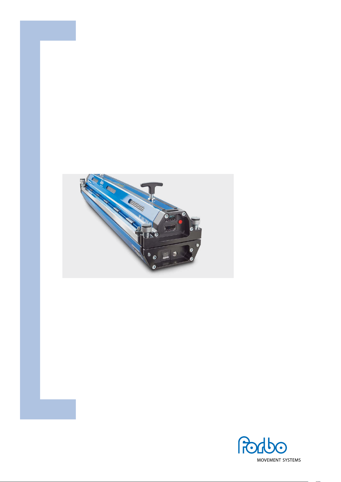
BLIZZARD HEATING PRESS
Contents
3 English manual
37 German manual
siegling blizzard
splicing equipment
TM

2
Dieses Gerät darf nur von Personen
in Betrieb genommen werden, die die
nachfolgende Betriebsanleitung gelesen
und verstanden haben.
Този уред трябва да се използва само
от лица, които са прочели и разбрали
следното ръководство за употреба.
本设备仅供阅读并理解以下使用手册
的人员使用
Dette apparat må kun sættes i drift af
personer, som har læst og forstået den
følgende driftsvejledning.
This device should only be used by
those personnel who have read and
understood the following user manual.
Seda seadet tohivad kasutada vaid ini-
mesed kes on lugenud kasutusjuhendit.
Tämä laite on tarkoitettu vain henkilöille,
jotka ovat lukeneet ja ymmärtäneet
kyseisen käyttöoppaan.
Cet appareil ne doit être mis en service
que par des personnes ayant lu et
compris les instructions de service ci-
après.
Αυτή η συσκευή επιτρέπεται να τεθεί σε
λειτουργία όνο από έλη του προσωπι-
κού που έχουν διαβάσει και κατανοήσει
τι οδηγίε χρήση που ακολουθούν.
Questo dispositivo può essere utilizzato
solo da persone che hanno letto e
compreso il seguente manuale.
この装置は、次の取扱説明書をよく読んで
理解した作業員のみが使用するようにして
ください 。
Ovaj uređaj mogu koristiti samo osobe,
koje su pročitale i razumjele upute
za upotrebu.
Šo ierīci drīkst lietot personāls, kurš ir
izlasījis un sapratis lietošanas instrukcijas.
Šį prietaisą leidžiama pradėti eksploatuoti
tik asmenims, perskaičiusiems ir supra-
tusiems toliau pateiktą instrukcijų žinyną.
Dit apparaat mag alleen door personen
in gebruik worden genomen die de
volgende gebruiksaanwijzing hebben
gelezen en begrepen.
To urządzenie może być użytkowane
tylko przez osoby, które przeczytały i
zrozumiały następującą instrukcję obsługi.
Este aparelho só pode utilizado por
pessoas, que tenham lido e compreendi-
do o Manual de instruções que se segue.
Acest aparat poate fi pus în funcţiune
doar de către persoanele care au citit și
au înţeles instrucţiunile de utilizare de
mai jos.
Bara de personer som har läst och
förstått den här bruksanvisningen får
använda den här apparaten.
Toto zariadenie môžu uviesť do prevádz-
ky len osoby, ktoré si prečítali nasledujúci
návod na použitie a porozumeli jeho
obsahu.
To napravo smejo uporabljati samo
osebe, ki so prebrale in razumele
naslednja navodila za uporabo.
Este aparato solo deben emplearlo
las personas que hayan leído y compren-
dido las siguientes instrucciones de uso.
Tento přístroj smějí uvádět do provozu
pouze osoby, které si přečetly následující
návod k obsluze a rozumějí mu.
A készülék üzembe helyezését csak olyan
személyek végezhetik, akik elolvasták az
alábbi használati utasítást és megértették
annak tartalmát.
3
INCORRECT or IMPROPER use of this heating press can cause injuries and damage
to the heating press. These instructions contain important information on how
the product works and safety issues. Please ensure you have read and under-
stood these instructions before you start operating the heating press. Keep this
manual handy for other users and owners so that they can read it before using
the heating press.
4 Main components
5 Technical information
6 Introduction
7 General safety rules
8 Safe operation
26 Design and diagrams
30 Power supply lead
wiring diagram
32 Wiring diagram
electrical components
36 Manufacturer‘s note/customer service/
EC declaration of conformity
OPERATING INSTRUCTIONS
BLIZZARD HEATING PRESS
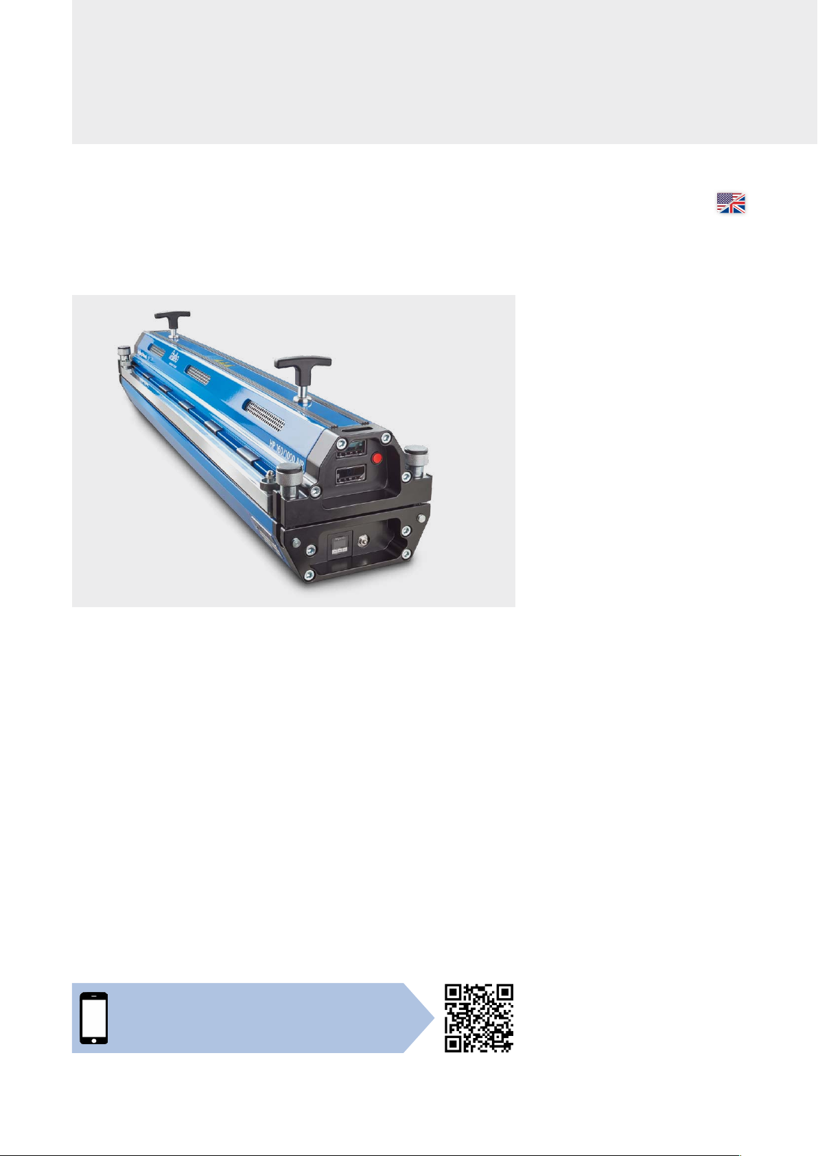
Blizzard HP 160/X00 | The web app
Device data, step-by-step instructions, current
belt-specific heating parameters for your work on site
https://blizzard.hp160-x00.forbo.com

4
Top part of the
heating press
Heating press connector screws (4 x)
Clamping bar nuts (4 x)
Clamping bars (2 x)
MAIN COMPONENTS
Connection side
Control
side
Handle
Connection side
Start button
Control side
Timer
Control unit for top part
of heating press
Control unit for bottom part
of the heating press
Pressure relief button
Pressure control switch
Socket to connect the
bottom part of the press
Connection for the main
and power supply leads
Socket to connect with
the top part of the press
Bottom part of the heating press

5
Main dimensions
TECHNICAL INFORMATION
Supplied with the
product and accessories
The following items are included with the heating
press: Leads, transport box and 2 silicone pads.
Embossing mats, glossy or matte release paper
(VEZ) are available as accessories on request.
Blizzard
HP 160/400 AIR
Blizzard
HP 160/600 AIR
Blizzard
HP 160/800 AIR
Blizzard
HP 160/1000 AIR
Blizzard
HP 160/1200 AIR
Blizzard
HP 160/1500 AIR
Effective belt width [mm (in)] 400 (15.7) 600 (23.6) 800 (31.5) 1000 (39.4) 1200 (47.2) 1500 (59)
Effective splice length max.
[mm (in)] 160 (6.3) 160 (6.3) 160 (6.3) 160 (6.3) 160 (6.3) 160 (6.3)
Weight bottom part [kg (lb)] 12 (26.5) 15.8 (34.8) 19.1 (42.1) 22.5 (49.6) 26. 2 (57.8) 31 (68.3)
Weight top part [kg (lb)] 14.6 (32.2) 18.6 (41) 22.7 (50) 26.9 (59.3) 30.9 (68.1) 36.8 (81.1)
Total weight [kg (lb)] 26.6 (58.6) 34.4 (75.8) 41.8 (92.1) 49.4 (108.9) 57.1 (125.9) 67. 8 (149.5)
Length [mm (in)] 590 (23.2) 790 (31.1) 990 (39) 119 0 (4 6.8) 1390 (54.7) 1690 (66.5)
Width [mm (in)] 230 (9.1) 230 (9.1) 230 (9.1) 230 (9.1) 230 (9.1) 230 (9.1)
Height top part [mm (in)] 118 (4.6) 118 (4.6) 118 (4.6) 118 (4.6) 118 (4.6) 118 (4.6)
Height bottom part [mm (in)] 84 (3.3) 84 (3.3) 84 (3.3) 84 (3.3) 84 (3.3) 84 (3.3)
Pressure max. [bar (psi)] 2.5 (36.3) 2.5 (36.3) 2.5 (36.3) 2.5 (36.3) 2.5 (36.3) 2 (29)
Max. temperature [°C (°F)] 200 (392) 200 (392) 200 (392) 200 (392) 200 (392) 200 (392)
Transport sizes (LxWxH) [mm] 875 x 370 x 350 875 x 370 x 350 1275 x 370 x 350 1275 x 370 x 350 1775 x 370 x 350 1775 x 370 x 350
Transport sizes (LxWxH) [in] 34.5 x 14.6 x 13.8 34.5 x 14.6 x 13.8 50.2 x 14.6 x 13.8 50.2 x 14.6 x 13.8 69.9 x 14.6 x 13.8 69.9 x 14.6 x 13.8
Weight when transported [kg (lb)] 42.1 (92.8) 49.9 (110) 61.9 (136.5) 69.5 (153.2) 83.8 (184.8) 94.5 (208.3)
Power requirements basic model
1 Phase [Volt /Ampere/ Watt]
article number
230 V/ 9A / 2200 W
Art. No. 873399
110V /14A / 1520 W
Art. No. 873400
230 V/ 14 A/ 3200 W
Art. No. 873401
110V /14A / 1520 W
Art. No. 873402
230 V/ 16 A/ 3680 W
Art. No. 873403
110V /14.5A /1600 W
Art. No. 873404
230 V/ 16 A/ 3680 W
Art. No. 873405
110V /14A / 1484 W
Art. No. 873406
230 V/ 16 A/ 3680 W
Art. No. 873409
230 V/ 19.5 A /4500 W
Art. No. 873412
230 V/ 16.0 A /3680 W
Art. No. 873413
230 V/ 13.0 A/ 3000 W
Art. No. 873414
3 Phase [Volt /Ampere / Watt]
article number
400 V/ 11A-5.5 A-5.5A
/
7600 W
Art. No. 873407
400 V/ 12 A-6.0 A-6.0 A/
8990W
Art. No. 873408
480V /11 A-5.5 A-5.5 A/
8900 W
Art. No. 873410
400 V/ 16 A-8.0 A-8.0 A/
11072W
Art. No. 873411
480V /13A-6.5 A-6.5 A/
10700 W
Art. No. 873415
Power requirements iCON type
1 Phase [Volt /Ampere / Watt]
article number
230 V/ 9A / 2200 W
Art. No 873417
110V /14A / 1520 W
Art. No 873418
230 V/ 14 A/ 3200 W
Art. No 873419
110V /14A / 1520 W
Art. No 873420
230 V/ 16 A/ 3680 W
Art. No 873421
110V /14.5A /1600 W
Art. No 873422
230 V/ 16 A/ 3680 W
Art. No 873423
110V /14A / 1484 W
Art. No 873424
230 V/ 16 A/ 3680 W
Art. No 873427
230 V/ 19.5 A /4500 W
Art. No 873430
230 V/ 16.0 A /3680 W
Art. No 873431
230 V/ 13.0 A/ 3000 W
Art. No 873432
3 Phase [Volt /Ampere / Watt]
article number
400 V/ 11A-5.5 A-5.5A
/
7600 W
Art. No
873425
400 V/ 12 A-6.0 A-6.0 A
/
8990W
Art. No 873426
480V /11 A-5.5 A-5.5 A/
8900 W
Art. No 873428
400 V/ 16 A-8.0 A-8.0 A/
11072W
Art. No 873429
480V /13A-6.5 A-6.5 A/
10700 W
Art. No 873433
Main dimensions in mm and inches (in).
All Imperial measurements have been
rounded up.
230 (9.1)
84 (3.3)
84 (4.6)
6
INTRODUCTION
The Siegling Blizzard heating press is a compact solution for heating thermoplastic conveyor belts (e.g. PVC, polyurethane).
No extra equipment such as an external control unit box, air pump or water tank are required. Siegling Blizzard heating
presses are heated electrically and air-cooled from inside. The heating procedure is fully automatic.
Problems can occur in thicker belts if the outsides of the belts are kept at the heating temperature for too long until the
inside has reached the required temperature. The melted material could dissolve or discolor and the fabric could shrink. The
pre-heating option can be used to prevent this from happening. This option heats the inside and outside of the belt to a
temperature just below melting point. After the pre-heating stage, the heating temperature on the inside is reached much
more quickly, minimizing the risk of material dissolving, discoloration or fabric shrinkage.
Basic procedure
• Heating pressure of up to 2.5 bar is generated.
Siegling Blizzard HP 160/1500 AIR: max. 2.0 bar
via the integrated compressor
• The heating device creates a heating temperature
of up to 200 °C
• The heating temperature is maintained
(adjustable dwell time)
• Cools down to the cooling temperature
(to a temperature safe enough to remove the belt)
• A pre-heat temperature and pre-heat dwell time
can be applied if belts are thicker.
• The two heating platens’ heating temperatures can be
adjusted so that they are different.
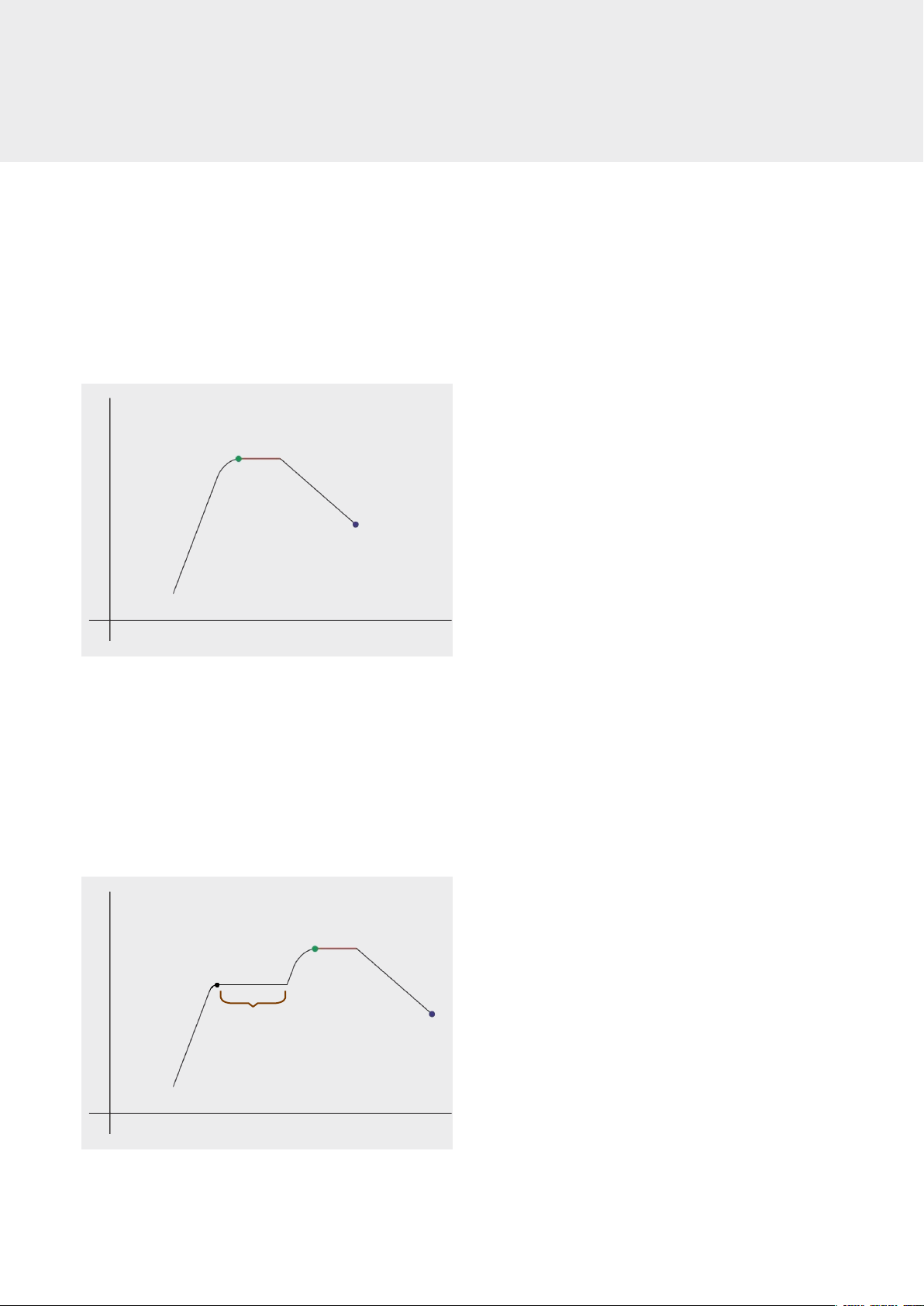
Graph of the procedure, program level 1
Settings:
Temperature
Time
Heating
temperature
Dwell time
Cooling temperature,
fan off
Graph of the procedure, program level 2 with pre-heating
Settings:
Temperature
Time
Heating
temperature Dwell time
Pre-heat
dwell time Cooling temperature,
fan off
Pre-heat
temperature
7
GENERAL SAFETY RULES
Risks
Danger indicates an immediate source of danger, which,
if ignored, may be fatal or lead to serious injuries. This safety
word is only used in exceptionally extreme circumstances.
Warning indicates a potential source of danger, which,
if ignored, could be fatal or result in serious injuries.
Caution indicates an immediate source of danger, which,
if ignored, could cause minor injuries. It can be used to warn
users not to use the device improperly.
Safety symbol
The purpose of this international safety symbol is to
call attention to specific safety issues.
General safety rules
Danger
In order to prevent serious injuries or damage to property,
please ensure you have read and understood this manual
before you start to operate the device.
Danger
Remove the main power supply cable from the socket or
the power outlet at the bottom of the device to rule out any
electrical hazards.
Warning
Press the red pressure relief button to rule out any pressure
hazards.
Caution
The press’s heating platens develop over 5 tons of clamping
force. Tighten the four heating press connector screws man-
ually before starting to operate the heating press.
Caution
To prevent any temperature hazards, only touch the
heating press’s components and the conveyor belt once
they have cooled down.
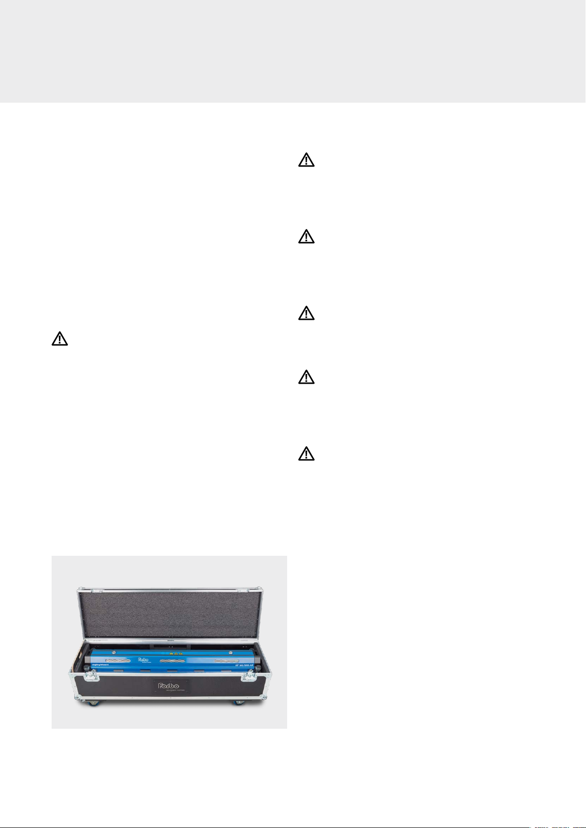
Transport box
• Siegling Blizzard heating presses come with a transport
box for storage purposes and so that the device is easy to
carry on site.
• Siegling Blizzard 400 – 1500 presses are stowed in transport
boxes with four wheels and a pull-out handle.
• The transport boxes can be stacked on top of each other,
but need to be secured during transportation.
• All transport boxes come with a pull-out handle to make
transporting them easier and more practical. Squeeze the
button in the handle to pull the handle out.
8
1
To operate the heating press, find somewhere with the right voltage and
connection options
Warning
Operating the heating press at the wrong voltage can cause serious damage and other
risks.
Before starting work, ensure you have enough belt material to cover the edges of the
heating press. The belt material for the edges must be of the same type and thickness
as the rest of the material.
2
Inspecting the power supply lead
Danger
a. Inspect the lead for any damage. Don’t use a damaged power supply lead. Either
replace the lead or ask an electrician to remove the faulty part and reattach the plug.
The electrician must refer to the wiring diagram on page 32 to ensure everything is
wired correctly.
b. Check whether the plug fits in the socket. If this isn’t the case, find another power
outlet or ask an electrician to attach the right plug (refer to the wiring diagram on
page 32).
Danger
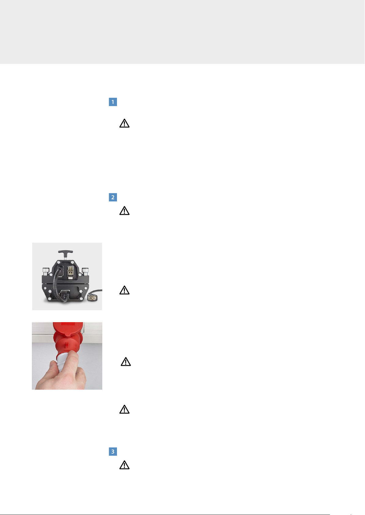
c. Don’t plug the power supply lead into the socket yet. As soon as all preparations to
connect to the socket have been carried out, follow these safe instructions:
– Use the connection lead to attach the top and bottom part of the heating press
with one another. (Fig. 1)
– Now attach the power supply lead to the power outlet at the bottom of the device.
– Put the plug into the socket. (Fig. 2)
Danger
– Never leave the power supply lead in the socket when the lead is not attached to the
device because this could be very dangerous if it comes into contact with liquids
such as water.
Danger
d. All the heating press’s electricity outlets and plugs have coded (uniquely shaped)
guide pins and jacks. This means it’s virtually impossible to connect it up wrongly.
3
Remove the heating press from the transport box
Heavy object
Note: Use proper lifting methods to prevent injuries. If you find it hard to lift the heating
press out of the transport box yourself, ask someone to help you.
SAFE OPERATION
Fig. 1
Fig. 2

9
4
Inspect the heating press for damage
Warning
Broken or missing components can make the workspace unsafe and therefore cause
more damage to the heating press or injuries to operatives.
Danger
a. Ensure that all four heating press connector screws are undamaged. Don’t attempt to
operate the heating press if a screw is broken or missing.
b. Inspect the press’s heating platens for damage.
c. Ensure that there are no deposits or dirt on the press’s heating platens. If dirty,
proceed as follows:
– Carefully wipe off any dirt and deposits with a clean cloth and an ammonium-based
cleaning agent.
Warning
– Don’t clean the heating platens with flammable solutions.
Caution
– Do not hose down the heating press with water. Soak a cloth in an ammonia-based
solvent and use it to wipe the heating press. Dry the heating press off with a clean,
dry cloth.
d. Ensure all the leads are in perfect condition. Don’t use the heating press if the leads
are damaged.
5
Checking the heating press works
Forbo Movement Systems recommends checking the heating press twice a year.
Tools required
–
Temperature measurement device (with ±1°C accuracy) including temperature sensor
– Pressure measurement device including pressure sensor
– Straightedge
Use the tools listed to check the temperature, pressure and flatness of your Siegling
Blizzard heating press’s heating platens. If the heating press doesn’t comply with the set
parameters, we recommend sending in the heating press for calibration or repair. Please
get in touch with your Forbo Movement Systems contact for more details.
Warning
– Before attaching the sensors, unplug the heating press from the power supply
– The press’s heating platens can be hot

10
SAFE OPERATION
6
Inspecting the silicone pads
In order to produce a perfect splice, the pads must have no dirt or deposits on them.
The pads can also be cleaned using an ammonia-based, non-flammable cleaning agent
that will not adversely affect the splice.
7
Removing the top part of heating press (Fig. 3)
a. Loosen all four heating press connector screws.
b. Grab the handles on the heating press to lift up the top part of the press
Heavy object
You might need to ask somebody else to help you lift the heating press depending on
its width and weight.
c. Place the bar to one side, without the heating platen facing downward. It’s important
to keep the heating platens in good condition at all times. The top part of the heating
press should lie on its side to protect the heating platens from scratches or getting
dirty. The top part of heating press has a rubber strip on the long side of the heating
press to prevent any scratches. (Fig. 3)
8
Insert the prepared ends of the belt into the heating press
a. Place a clean silicone pad onto the clean bottom heating platen. Ensure the silicone
pad lies flat because any creases will impact the appearance of the splice. The pur-
pose of the silicone pads is to prevent the belt material from sticking to the press’s
heating platens.
b. Place the prepared ends of the belt onto the bottom heating platen.
Note: The area heated is 160 mm wide and situated in the middle of the heating plat-
en. Make sure the area to be heated is correctly centered. Depending on the belt
type, slight heat loss can occur in the outer areas of the heating zone. A prepared fin-
ger splice or layer separation must be within the heating zone because otherwise the
material won’t melt outside the heating zone. (Fig. 4)
Fig. 4
Nominal width + 100 mm
Nominal width 400 – 1500 mm
160 mm
Heating area
Protective
rubber strip
Handle
Handle
Heating press
connector screws (4 x)
Fig. 3
11
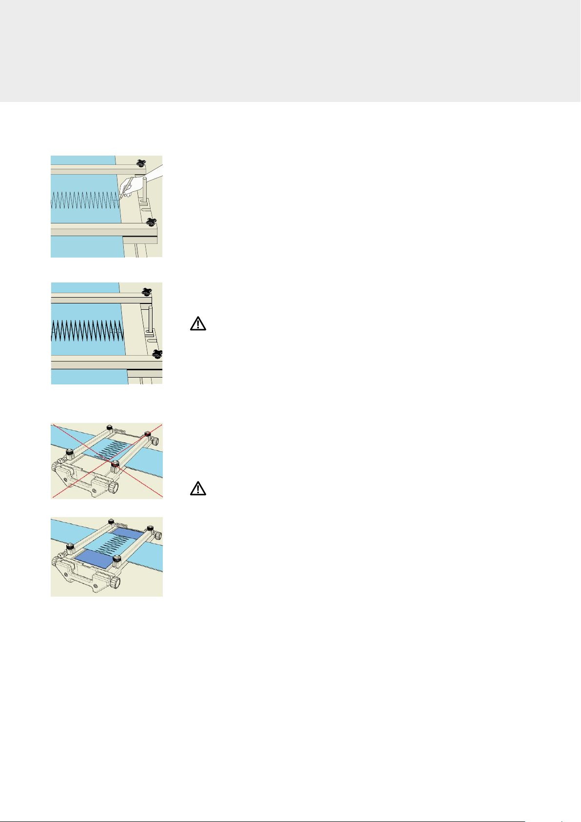
c. Please follow this procedure if you want to make a finger splice:
– For splices without any additional materials:
The fingers must interlock completely and there must be no gaps between the
fingertips. Distance between the fingers = 0 mm
– For splices with film on the top face:
Push the fingers into one another completely and draw a marking line (see Fig. 5).
Then pull the ends of the belt apart again until there is a 6 mm distance between
the lines. The distance between the fingers is 2 mm. (Fig. 6).
d. Apply extra belt material to the edges of the belt to be spliced until all of the heating
press is covered over the entire area to be pressed. This prevents melted material
from being squeezed out.
Caution
Ensure the belt material covers the entire width of the heating press so that even pres-
sure is applied and damage to the press prevented.
e. Apply the clamping bars so that the fingers are secured firmly onto the bottom part
of the press.
f. Depending on the splicing instructions for the material to be prepared, place film/
release paper/silicone pad onto the prepared heating zone. Ensure no creases form.
Incorrect: Area at the edge not covered (Fig. 7)
Correct: Area at the edge covered with extra belt material (Fig. 8)
Caution
Don’t use any metal shim bars due to the risk of thermal bridges forming between the
top and bottom heating platen.
Fig. 7
Fig. 8
Fig. 5
Fig. 6
12
9
Insert the top part of heating press
a. Carefully place the top part of heating press onto the prepared ends of the belt.
Ensure that the prepared ends of the belt or the fingers aren’t separated.
Heavy object
Ask another person to help you if you find it hard to lift the heating press because of
its width or weight.
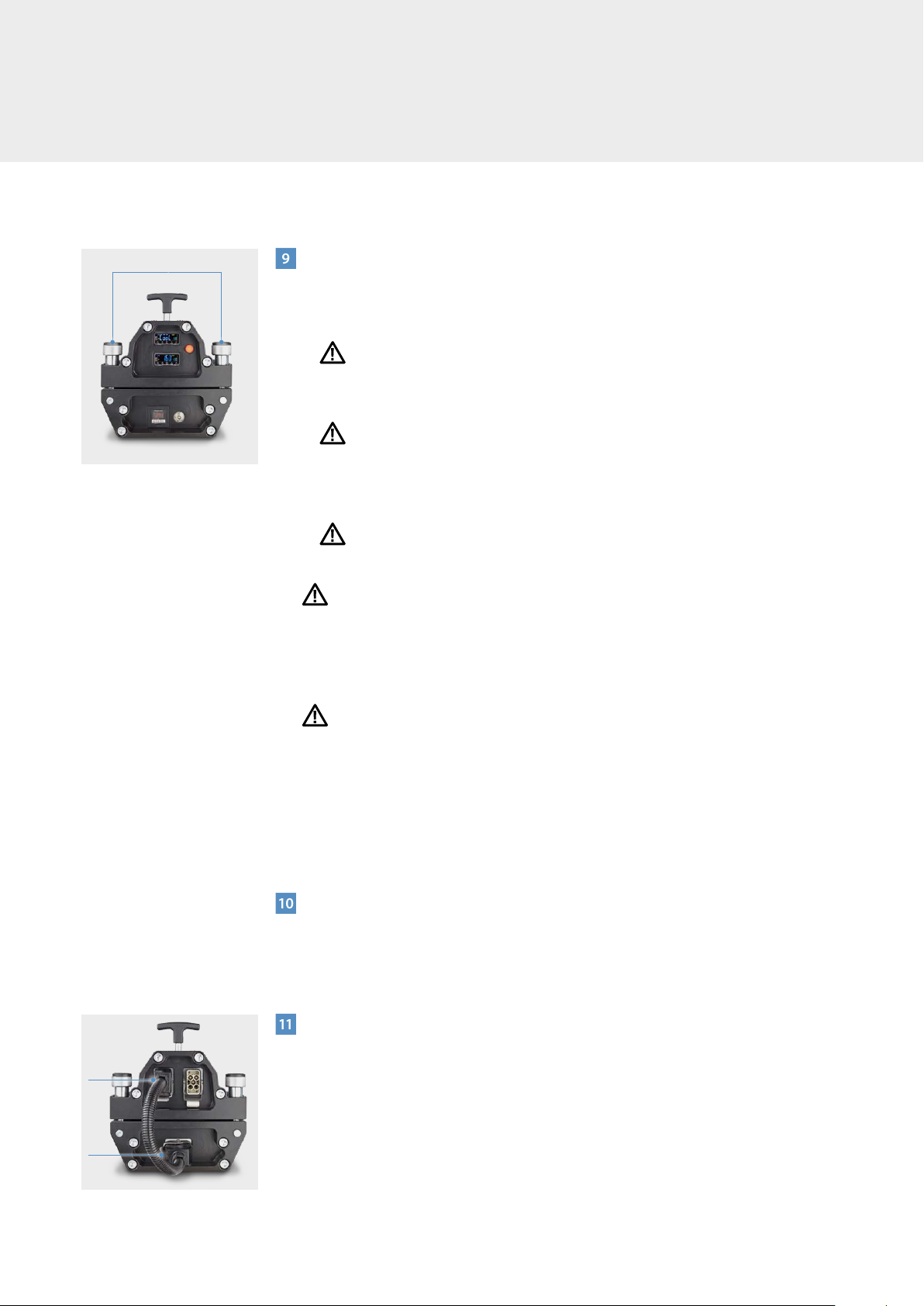
Danger
b. Center the top bar so that all four connecting screws can easily rotate upward. This is
vital in order to align the heating press correctly. Tighten the screws by hand and
ensure these are positioned properly in the recess on the top bar. (Fig. 9)
Caution
Ensure you don’t get your fingers caught in areas where they could be crushed.
Danger
The heating press can exert pressure of up to 2.5 bar.
Do not operate the heating press if a screw is missing or broken as this could cause seri-
ous injury and/or damage to the press. Missing or broken screws may only be replaced
by parts authorized by the company.
Warning
To ensure the screws engage properly with the thread, the prepared ends of the belt
(including the pads) must not exceed 15 mm (0.59 in). This would not necessarily impair
the heating press’s ability to heat. If this thickness is exceeded, the threads on the con-
necting screws can’t reliably clamp to the heating press, which could damage the heat-
ing press and lead to injuries.
10
Remove clamping bars as soon as the top part of heating press has been secured
If the clamping bars can’t be removed, it is possible that heating might not be even
across the belt width.
11
Using the power lead to connect the top and bottom part of the press (Fig. 10)
a. Put the power lead’s plug into the cable connector at the bottom of the device.
b. Lock the plug in place. If the plug is not locked in place, the power supply to the
controls at the base of the heating press might be temporarily interrupted.
SAFE OPERATION
Lock
Lock
Heating press connector screws (4 x)
Fig. 9
Fig. 10
13
Lock
Fig. 11
Fig. 12
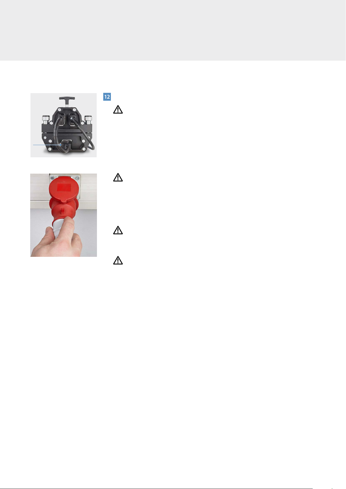
12
Connecting the power supply lead to the heating press (Fig. 11)
Warning
It is very important that the power cable is connected to the heating press first and
then to the socket. Doing this in reverse order could cause a fatal electric shock and
dangerous electrical arcing.
a. Pull the power supply lead’s plug out of the power outlet at the bottom of the
device.
b. Lock the plug in place. If the plug is not locked in place, the power supply to the
heating press might be temporarily interrupted.
Danger
c. Double check to ensure that the voltage and connections are appropriate for the
power supply lead. Incorrect or too much voltage can cause serious damage to the
heating press and accidents (e.g. a short circuit or a fire to break out if a 230-volt
cable is connected to a 460-volt socket).
d. Now insert the power supply lead into the appropriate socket. (Fig. 12)
Important
Only plug the power supply lead into the socket once it has been connected to the
heating press.
Danger
e. If you connect a plug to a bare power lead or a permanently fitted cable, you must
always comply with the wiring diagram for the power supply lead shown on
page 30. Ensure that the right wiring diagram is used for the lead concerned. Ensure
that the right plug is used. This may only be done by qualified personnel.
The heating press has three controls:
1. Temperature control on the top part of heating press to adjust:
The heating temperature at the top (200°C max.), pre-heat temperature at the top.
2. Temperature control on the bottom part of the heating press to adjust:
The heating temperature at the bottom (200°C max), dwell time,
pre-heat temperature at the bottom and cooling temperature.
3. Pressure control switch on the bottom part of the press. This controls the pressure
of up to 2.5 bar.
14
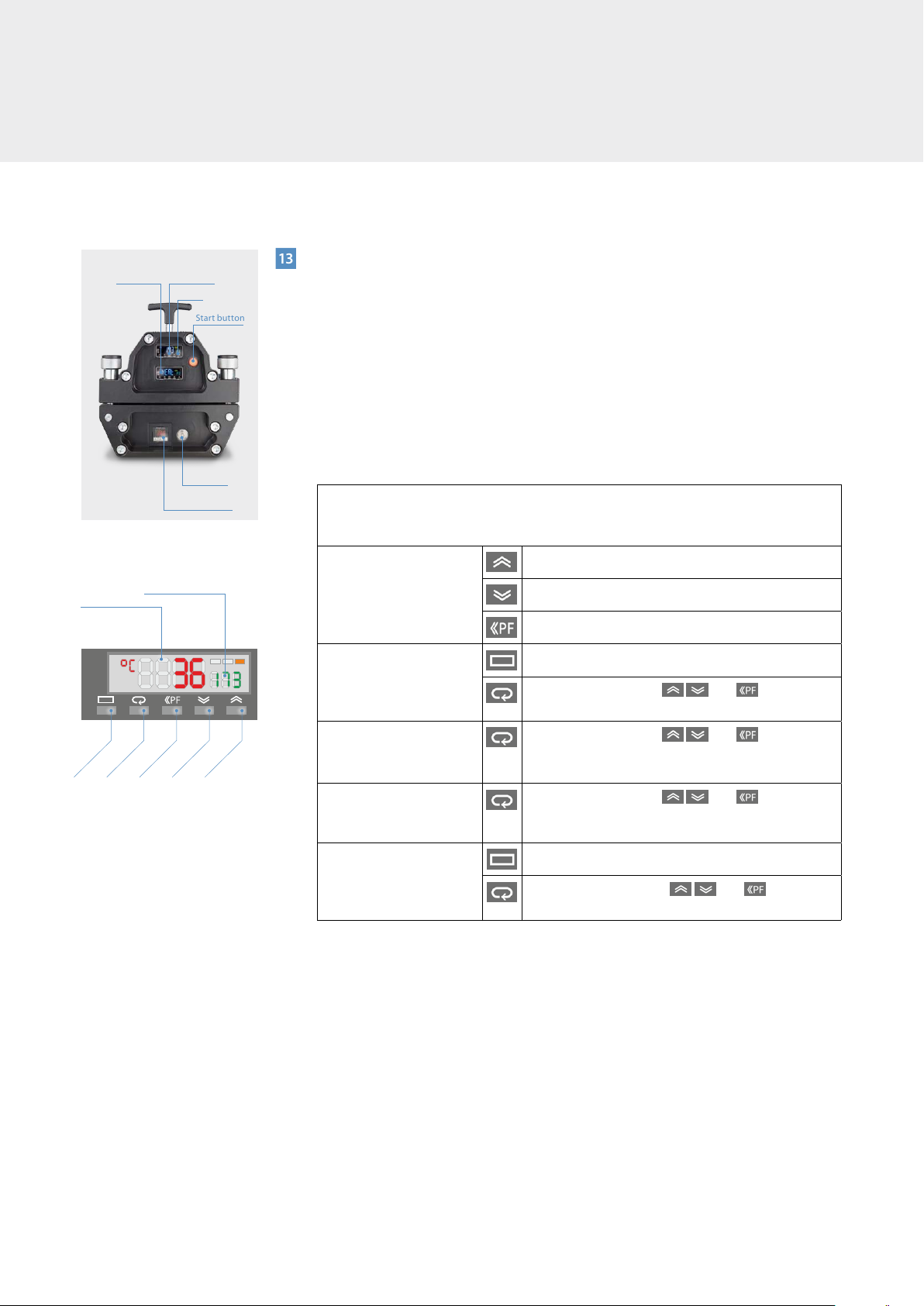
13
Configuring the parameters
The Blizzard heating press has two digital control units, a pressure switch and an air
bleeder knob. These components can be used to set all process parameters. (Fig. 13)
a. Digital control unit on the bottom part of the press
Control functions: – Heating temperature at the bottom and relevant dwell time
– Pre-heat temperature at the bottom and relevant dwell time
– Cooling temperature
Please refer to the following table to set the heating parameters:
b. Digital control unit for the top part of the press
Control functions: – Heating temperature at the top
– Pre-heat temperature at the top and relevant dwell time
– Parameters are entered in the same way as for the bottom part of the press’s digi-
tal control unit. The heating temperature’s dwell time and the cooling tempera-
ture are taken from the settings for the bottom part of the press. This means that
SoAK and AL-1 will not be shown.
c. Pressure switch
Select the required working pressure and maximum pressure deviation, which would
restart the compressor should pressure drop. (Forbo Movement Systems recom-
mends working pressure of -0.2 bar). As soon as the heating press is connected to
the mains, the display shows the current pressure, in other words 0 bar when idle.
Start button
Timer
Top
controller
Bottom
controller
Air bleeder
button
Pressure switch
Fig. 14
Function Key
Mode Key
Digit Key
Minus Key
Plus Key
Display nº 1
Display nº 2
Display 1 on the main screen (Fig. 14) shows the current temperature.
Display 2 shows the heating temperature selected (default: 173°C).
Before pressing the start button, display 1 shows StoP.
Adjusting the heating
temperature
Increasing temperature
Decreasing temperature
Jump to 1, 10 or 100 decimal places
Adjusting the pre-heat
temperature SP-0
LAdj
Use the arrow buttons and to adjust
the pre-heat temperature
Adjusting the dwell time
SoAK Use the arrow buttons and to adjust
the pre-heat temperature and dwell time (default:
240 s)
Adjust the dwell time’s
pre-heat temperature
W60-N
Use the arrow buttons and to adjust
the pre-heat temperature and dwell time
Cooling temperature AL-1 Back to the main screen StoP
Press the arrow buttons and to adjust
the cooling temperature (default: 70°C)
Fig. 13
SAFE OPERATION
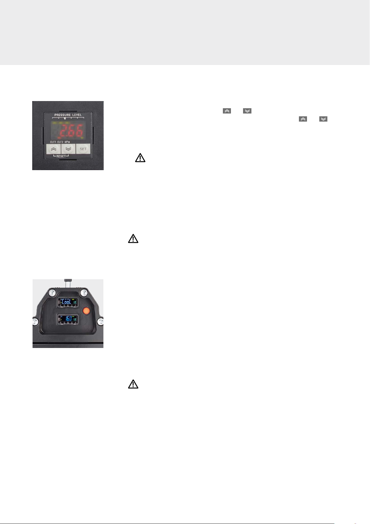
15
– Briefly press the SET button to access OUT1 (on). Then select the maximum
working pressure by pressing the + or – buttons (2.5 bar max.). (Fig. 15)
– Then briefly press SET again to access OUT1 (off). Then press the + or –
buttons to adjust the pressure at which the compressor switches on again to
achieve the working pressure set. This figure should be 0.2 bar lower than the
working pressure.
Warning
Make sure that this figure is 0.2 bar lower than the working pressure because the
pressure control could be damaged otherwise.
– Then press SET again for about 3 seconds. The main screen will then show the
current pressure.
The heating press has a pressure relief device that restricts maximum pressure
to 2.7 bar.
Warning
When the main screen is open, don’t press the SET button for a long period of time.
Otherwise, the screen will display Unt. In this case, press SET again for about 3 sec-
onds to return to the main screen.
d. Start button
Once all the parameters have been set and the belt is prepared, start the process
by pressing the button on the top part. This button will light up during the entire
process. (Fig. 16)
– Before pressing the start button, make sure that all the screws have been
tightened.
– As soon as the process has been completed and the fans switch off because the
heating press has reached the cooling temperature, a buzzer will indicate that
the process is finished. The buzzer must be deactivated manually.
e. Air bleeder knob
As soon as the process is finished, press the air bleeder knob to release the pressure.
Danger
Ensure that the start button has been switched off. Otherwise, the air compressor
will switch on again to generate pressure. This can cause injuries or damage the
heating press.
– If you want the press to repeat a process, just press the start button again and the
press will make another splice.
– Once the pressure has been released, carefully remove the top part of the heating
press.
– Once the mains plug has been pulled out of the heating press, the last splice’s
parameters are stored.
Fig. 16
Fig. 15

16
If you’ve chosen a Blizzard HP with an iCON app control, you can leave out step 13
and operate the Blizzard HP via the app. Point 14 describes how to do this. Otherwise
proceed to point 15.
14
Operating the Blizzard HP via the iCON app
a. Connecting with the iCON heating press
The Blizzard heating press with iCON has an extra module that the press uses to
generate a Wi-Fi signal. In order to control the heating press with your mobile device,
connect to the Wi-Fi network belonging to the press which is connected to the
power supply:
Wi-Fi network (SSID) iCON-XXXXXX
Wi-Fi password forboicon
Open a browser on your mobile device and enter the following address:
http://192.168.1.1
Depending on your mobile device’s operating system, we recommend using the
following
iOS: Safari Unix: Chrome
Android: Chrome Windows: Chrome
b. Logging in or creating a new user
Once you’ve entered your address in your browser’s address bar, you’ll be forwarded
to the log-in section (Fig. 17). Click on to choose the language required. The lan-
guage can be changed in the settings (section d). If you already have a user account
on this heating press, enter your e-mail address and click on Submit. Enter your pass-
word in the next screen that appears. If your log-in data is correct, you’ll be forward-
ed to the cockpit.
If you’re logging in for the first time (Fig. 18), enter your e-mail address that you’d like
to log in with in the future and press Submit. Once you’ve read and accepted the
terms of use (by clicking on terms of use)*, enter your name in the window and con-
firm by clicking on Submit. You will now be asked to provide a password. You will
then be able to log on as described above.
* Your data will only be stored in the iCON heating press’s own memory. The data won’t be
stored anywhere else. You can only enter your user data to log onto the heating press for
which you are a registered user.
SAFE OPERATION
Fig. 18
Fig. 17
17
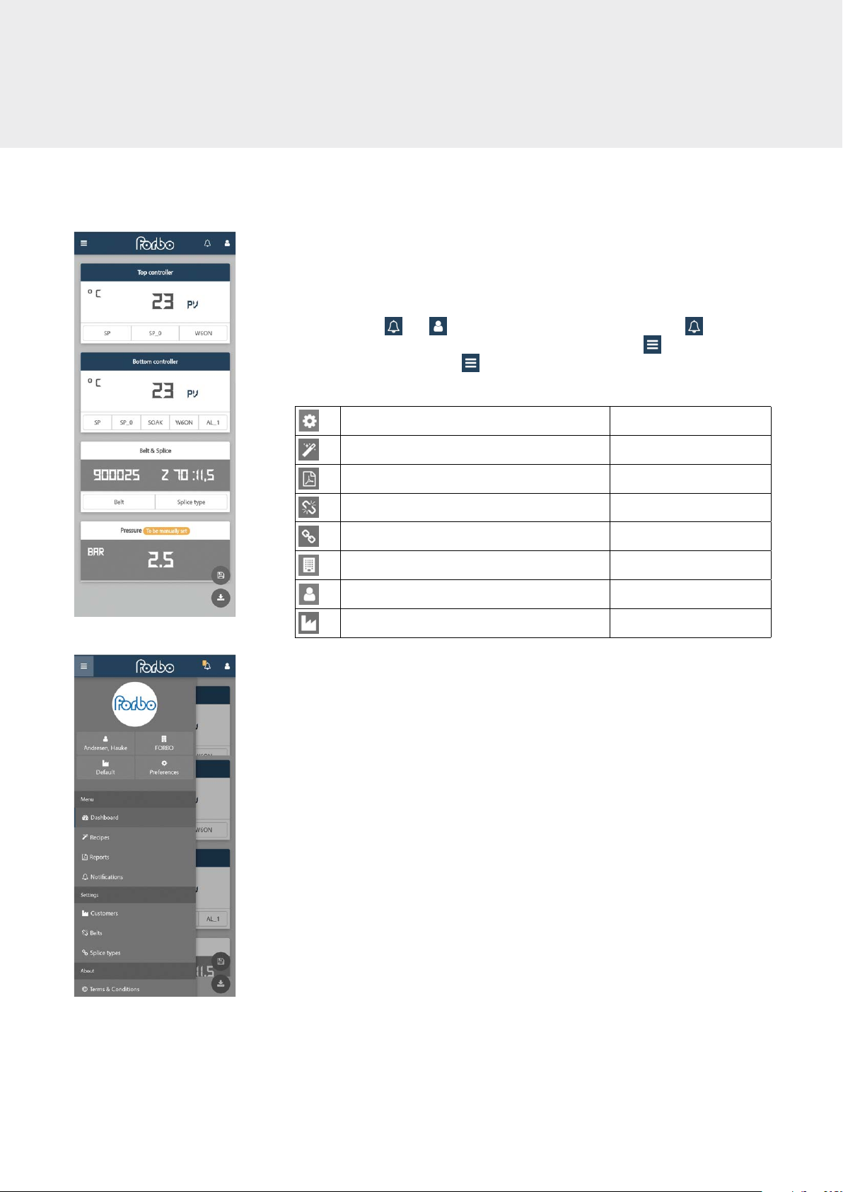
c. Cockpit and options menu
Once you’ve logged in, you’ll be forwarded to the cockpit (Fig. 19). You can enter the
heating parameters here (section e), store them (section f) and retrieve recipes
already stored (section g).
You will find the and symbols in the top right-hand corner. The symbol
will display notifications, e.g. about missing entries. Clicking on will show the
log-out button. By clicking on in the top-left corner, you’ll access the options
menu (Fig. 20). This will give you access to the following menus:
Preferences Section d
Managing recipes Section g
Retrieving reports Section h
Managing belts Section i
Managing splice types Section j
View company account Section h
View current user data Section l
Selecting and managing customers Section m
Fig. 19
Fig. 20

18
d. Settings
You can reach the settings (Fig. 21) via the options menu (section c) and by clicking
on . You can enter the relevant language and time zone here.
To select the language, click on the dropdown menu in the top box under language.
You can choose between the following languages:
German English French Spanish
Italian Chinese Japanese Korean
You can select the time zone in the time zone section. Select the right one from the
dropdown menu.
Save your language and time zone by clicking on the submit button.
e. Configuring the parameters
You can enter the heating parameters in the cockpit (Fig. 22). Each of the parameters
are explained in the table below:
Click on the buttons and a box will appear where you can add your entry (Fig. 23).
Clicking on confirms the entry you have made and sends it to the heating press.
Enter the air pressure for the heating procedure. To do so, click in the appropriate box
(Fig. 24). Please note that for safety reasons, the air pressure must be set manually on
the press control unit. The air pressure entered into the iCON control unit appears on
the heating procedure report (section h).
Name Top/bottom part
of the heating press Meaning
SP
Top part of the press
Heating temperature
SP_0 Pre-heat temperature
W6ON Pre-heat temperature dwell time
SP
Top part of the press
Heating temperature
SP_0 Pre-heat temperature
SOAK Heating temperature dwell time
W6ON Pre-heat temperature dwell time
AL_1 Cooling temperature
SAFE OPERATION
Fig. 21
Fig. 22
Fig. 23
Fig. 24

19
After entering the parameters, click in the belt & splice box to enter the belt type and
relevant splice. A dropdown list (Fig. 25) appears once you have clicked on Belt. You
can select an existing belt type here.
If the belt type is not on the list, click on next to the dropdown list. Now add the
article number and the name of the belt type in the window and click on Save. You
can then select the belt types in the dropdown list. Section i describes how to man-
age the stored belt types.
Proceed in the same way for the splice type. Click on splice on the belt & splice
menu and select the splice type from the dropdown list.
If it’s not there, add it by pressing (Fig. 26). Section j describes how to manage
the splice types.
Before starting the heating, enter your customer’s information or select an existing
customer (see section l). This is the only way of ensuring that these customer data
are displayed correctly on the report.
After entering all the data and parameters in the heating press, you can start the
heating procedure as usual by pressing the press’s start button. You can monitor the
procedure on your mobile device. (Fig. 27)
f. Storing recipes
Heating parameters can be stored for quick and easy retrieval in future. To store the
parameters, enter these into the home screen as described in section e.
Then click on (Fig. 28). A window will then open with a field for the name of the
recipe so that you can find it afterwards (pre-saved recipes are stored with “Article
Number Splice Type”, e.g. 900025 Z 70:11.5). Click on Submit to confirm you want to
save it. (Fig. 29)
Fig. 25
Fig. 26
Fig. 27
Fig. 28
Fig. 29
20
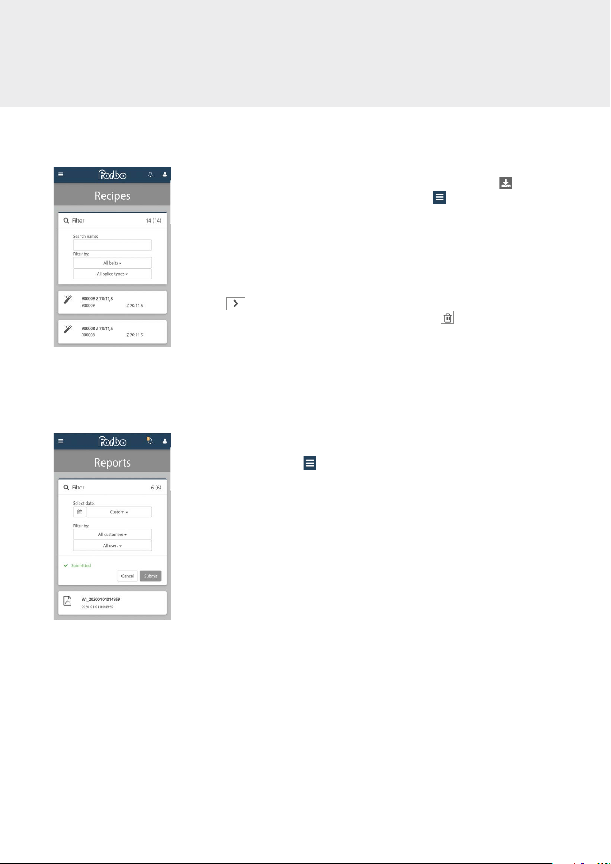
g. Retrieving and managing stored recipes
In order to retrieve recipes that you or the factory have stored, click on in the
cockpit to get to the recipe menu. Or you can click on i in the top left-hand cor-
ner. The options menu will then open (section c). Click on recipes to get to the recipe
menu. (Fig. 30)
This menu provides a list of all recipes stored on the heating press. You can use the
filter to find a recipe easily.
Click on one of the recipes to display all the relevant recipes and information. Click
on to confirm your selection and the data will be sent to the press. You will
then be sent to the home screen automatically. Click on to delete a recipe select-
ed.
After selecting a recipe, you can start the heating procedure as usual by pressing the
press’s start button. You can monitor the heating procedure on your mobile device
(Fig. 27).
h. Retrieving reports
The Blizzard iCON heating press logs every heating procedure in detail and stores it
automatically. Click on in the top left-hand corner to get to the options menu
(section c). Click on Reports to get to the menu required (Fig. 31).
SAFE OPERATION
Fig. 30
Fig. 31
Other manuals for siegling blizzard HP 160/400 AIR
1
This manual suits for next models
39
Table of contents
Languages:
Other Forbo Power Tools manuals


Popular Power Tools manuals by other brands


Edge Craft
Edge Craft Chef'sChoice 490 instructions

Panasonic
Panasonic EY7440 - DRILL DRIVER 14.4V- MULTI-LANG operating instructions

Hakko Electronics
Hakko Electronics FR400-53 instruction manual

Bosch
Bosch PKP 7 Original instructions

MasterCraft
MasterCraft 058-9847-6 operating manual

Skil
Skil SHD77-02 Operating/safety instructions


