Forbo Blizzard SHP X00 User manual

Siegling – total belting solutions
OPERATING INSTRUCTIONS
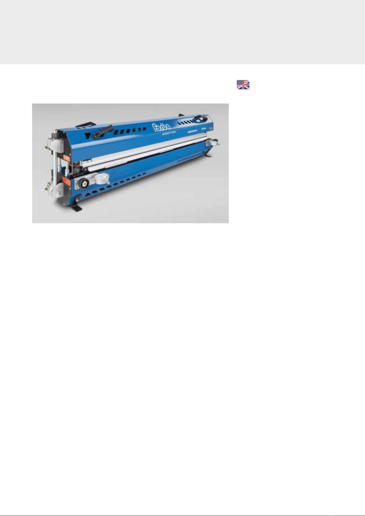
BLIZZARD SLIM HEATING
PRESS (SHP) X00
Contents
3 English manual
33 German manual
siegling blizzard
splicing equipment
®

2
Dieses Gerät darf nur von Personen
in Betrieb genommen werden, die die
nachfolgende Betriebsanleitung gelesen
und verstanden haben.
Този уред трябва да се използва само
от лица, които са прочели и разбрали
следното ръководство за употреба.
本设备仅供阅读并理解以下使用手册
的人员使用
Dette apparat må kun sættes i drift af
personer, som har læst og forstået den
følgende driftsvejledning.
This device should only be used by
those personnel who have read and
understood the following user manual.
Seda seadet tohivad kasutada vaid ini-
mesed kes on lugenud kasutusjuhendit.
Tämä laite on tarkoitettu vain henkilöille,
jotka ovat lukeneet ja ymmärtäneet
kyseisen käyttöoppaan.
Cet appareil ne doit être mis en service
que par des personnes ayant lu et
compris les instructions de service
ci-après.
Αυτή η συσκευή επιτρέπεται να τεθεί σε
λειτουργία όνο από έλη του προσωπι-
κού που έχουν διαβάσει και κατανοήσει
τι οδηγίε χρήση που ακολουθούν.
Questo dispositivo può essere utilizzato
solo da persone che hanno letto e
compreso il seguente manuale.
この装置は、次の取扱説明書をよく読んで
理解した作業員のみが使用するようにして
ください 。
Ovaj uređaj mogu koristiti samo osobe,
koje su pročitale i razumjele upute
za upotrebu.
Šo ierīci drīkst lietot personāls, kurš ir
izlasījis un sapratis lietošanas instrukcijas.
Šį prietaisą leidžiama pradėti eksploatuoti
tik asmenims, perskaičiusiems ir supra-
tusiems toliau pateiktą instrukcijų žinyną.
Dit apparaat mag alleen door personen
in gebruik worden genomen die de
volgende gebruiksaanwijzing hebben
gelezen en begrepen.
To urządzenie może być użytkowane
tylko przez osoby, które przeczytały i
zrozumiały następującą instrukcję obsługi.
Este aparelho só pode utilizado por
pessoas, que tenham lido e compreendi-
do o Manual de instruções que se segue.
Acest aparat poate fi pus în funcţiune
doar de către persoanele care au citit și
au înţeles instrucţiunile de utilizare de
mai jos.
Bara de personer som har läst och
förstått den här bruksanvisningen får
använda den här apparaten.
Toto zariadenie môžu uviesť do prevádz-
ky len osoby, ktoré si prečítali nasledujúci
návod na použitie a porozumeli jeho
obsahu.
To napravo smejo uporabljati samo
osebe, ki so prebrale in razumele
naslednja navodila za uporabo.
Este aparato solo deben emplearlo
las personas que hayan leído y compren-
dido las siguientes instrucciones de uso.
Tento přístroj smějí uvádět do provozu
pouze osoby, které si přečetly následující
návod k obsluze a rozumějí mu.
A készülék üzembe helyezését csak olyan
személyek végezhetik, akik elolvasták az
alábbi használati utasítást és megértették
annak tartalmát.
3
OPERATING INSTRUCTIONS
BLIZZARD SHP X00
ENGLISH
Contents
4 Safety
6 Description
9 Preparation
12 Operating the device
30 Maintenance and repairs
32 Information from the manufacturer/
customer service,
EC declaration of conformity
These instructions provide important information on how the device works
and how to use it safely. Don’t use the device until you have read and understood
the instructions. Keep these instructions in a handy place for other users so that
they can read them before using the device.
Incorrect or improper usage can cause damage to the device and the conveyor
belt, as well as injury to the operative and other people.

4
1 SAFETY
These instructions provide important information on serious
risks associated with operating the Blizzard SHP X00, impor-
tant technical information and processes applied.
Symbols are used to highlight this important information
and indicate as follows:
This symbol is always used in conjunction with a
hazard and the relevant signal word.
In the text, key signal words mean as follows:
Danger means a personal hazard with a high level of risk,
which, if not prevented, will be fatal or result in serious
injury.
Warning means a personal hazard with an average level
of risk, which, if not prevented, could be fatal or result in
serious injury.
Caution means a personal hazard with an average degree
of risk, which, if not prevented, might result in a minor or
moderate injury.
Notice is a warning about damage to property and the
environment.
The device may only be operated in the following circum-
stances:
– In compliance with its intended use
– In compliance with the operating instructions
– When in perfect condition and only with the original
accessories
– When operatives are aware of safety requirements and
hazards
– If servicing and maintenance work has been
carried out correctly (only by the manufacturer or
appropriately qualified staff).
1.2 Intended use
The Blizzard SHP X00 is designed for melt splicing homoge-
neous belt material (Siegling Fullsan) up to a maximum tem-
perature of 230 °C. The ends of the belt are butt spliced in
the press under pressure and temperature.
The Blizzard SHP X00 is a heating press used for assembly
purposes and not suitable for continuous operation. After
several heating processes (5 to 8 cycles), the press needs to
cool down to room temperature before it’s used again.
It’s not intended to be used for any other purposes.
1.3 Organizational measures
The operating instructions must always be kept near the
device and within easy reach. In addition to these operating
instructions, abide by general legal and other mandatory
regulations on accident prevention and environmental pro-
tection.
To reflect special operational features, further instructions
can be added to the operating instructions, regarding:
– Work organization and procedures
– The personnel deployed
– Supervisory and reporting duties
1.1 General safety information
The Blizzard Slim Heating Press (SHP) X00 is a state-of-the-art
device and governed by the EC Machine Directive’s health
and safety requirements. Nevertheless, using it may cause
injury to life and limb of the user or third parties, as well as
damage to the machine and other property.

5
1.5 Moving the device
Unplug the device from the power supply every time you
move it somewhere else. Reconnect the device to the mains
before switching it on again.
If lifting the device, only use lifting gear and equipment with
sufficient load-bearing capacity. Only attach lifting gear or
equipment to the handles or ring bolts (see section 2). Make
sure that no parts of the device can fall off or become loose
while it’s being transported.
Warning
Make sure that the top and bottom section of the press are
properly screwed together.
1.6 Further important information
Danger
Opening the device entails a risk of accidents.
Conversions and maintenance work may only be carried out
by trained and skilled personnel. Repairs may only be car-
ried out by the manufacturer or people appointed by the
manufacturer.
Notice
Fire hazard. Ensure that you can always access the heating
press and it’s not covered over when it’s cold.
Danger
The devices are not protected from electrical overload.
Therefore, the operator must ensure that the electrical
installation is protected from overload in the place it is oper-
ated. A device’s electrical components must be inspected/
checked frequently. Any obvious faults, such as loose con-
nections, must be put right immediately.
Only personnel who have been briefed and read the operat-
ing instructions are permitted to use the device. Frequent
checks are to be made to ensure that people are complying
with the operating instructions and are aware of safety
requirements and hazards.
Take the following precautions to minimize the risk of injury:
– Wear closely fitting clothing
– Tie long hair back
– Take jewelry, including rings, off before starting work
Make sure that all the device’s safety and hazard instructions
are observed and easy to read.
If the device starts behaving abnormally, switch it off
immediately and report the fault to the department/person
concerned.
Don’t modify, add to or convert the device without the
manufacturer’s approval. Anyone who makes subsequent
additions to, or conversions of the device, is responsible for
ensuring compliance with the EU directive.
Only original spare parts meet the technical requirements
specified by the manufacturer and guarantee that the
device will work perfectly.
1.4 Selecting and briefing personnel
The device may only be operated by personnel who are
qualified and have been briefed to do so.
Work on the device’s electrical components may only be
carried out by the manufacturer or people appointed by the
manufacturer.

6
2 DESCRIPTION
2.1 The Blizzard SHP’s X00 (basic device) design and components
Bottom section
Top section
Air inlets for cooling
Handles (4x)
Compressed air regulator
Connectors (2x)
Fig. 2.1.1 (left)
Please note: The SHP 1500 and SHP 2000 have ring bolts
on the top section so they can be transported.
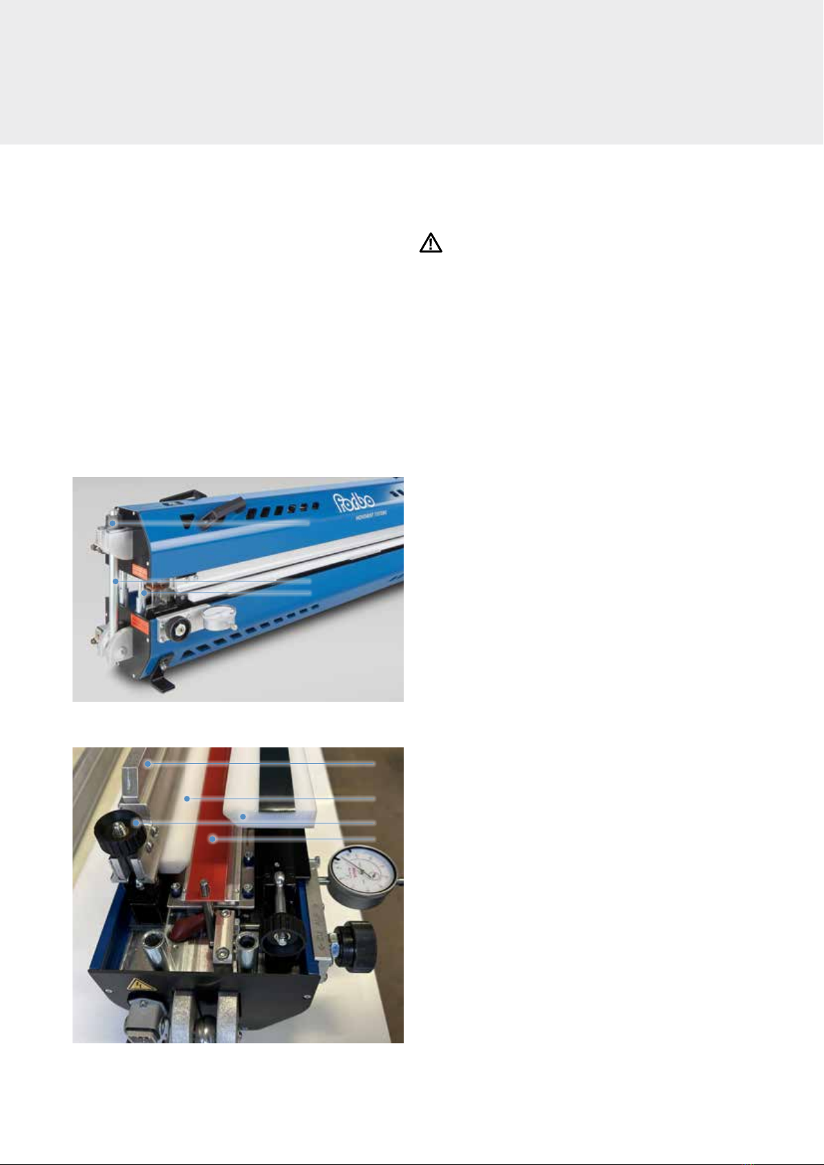
Fig. 2.1.2
Inlays
Belt holder (2x)
Knurled nuts (4x)
Top section
Eye bolt with collar nut (2x)
Dial gauges (2x)
(can be removed when device is transported)
Belt set screws (2x)
Centering bolts (4x)
Laminated fabric inlays top and bottom
Fig. 2.1.3
7
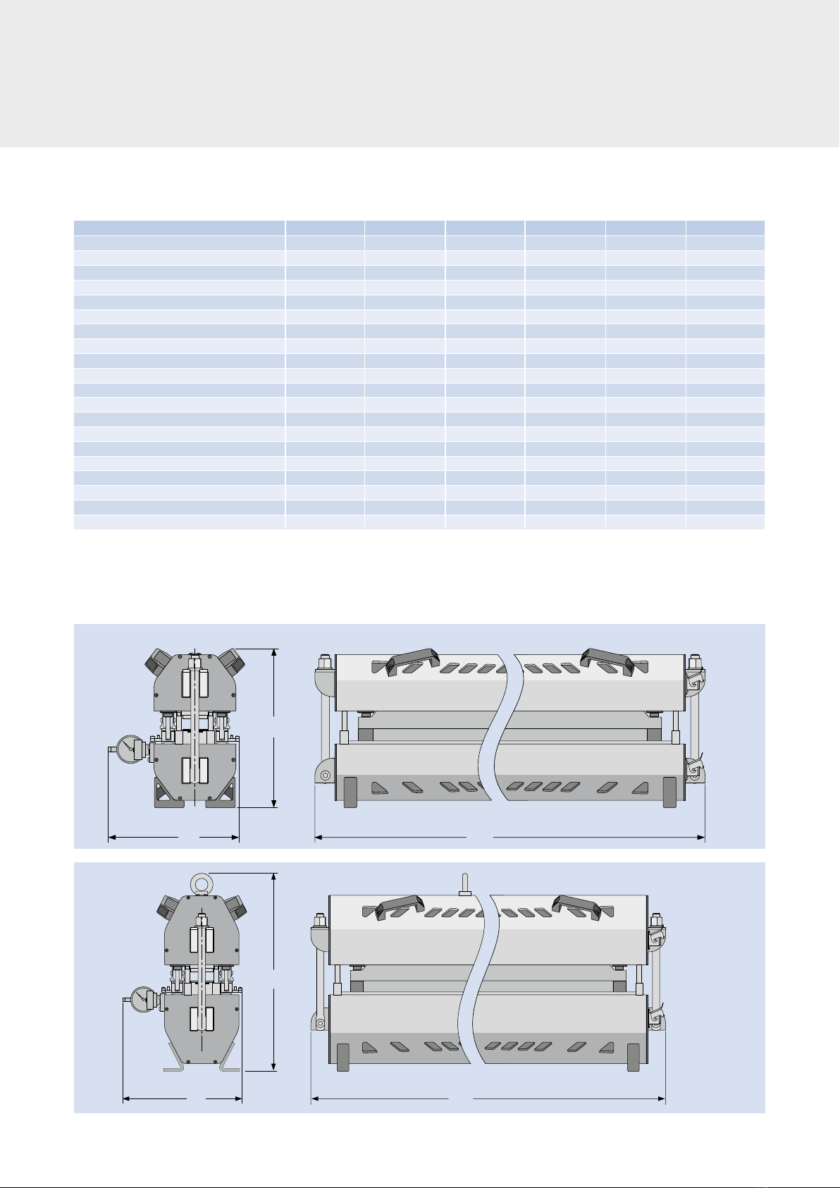
SHP 1500 / SHP 2000
SHP 600 … SHP1200
H
H
L
L
B
B
SHP 300 SHP 600 SHP 900 SHP 1200 SHP 1500 SHP 2000
Belt width max. (at 90°) [mm (in)] 300 (11.8) 600 (23.6) 900 (35.4) 1200 (47.2) 1500 (59.1) –
Belt width min. (at 90°) [mm (in)] – 300 (11.8) 600 (23.6) 900 (35.4) 1200 (47.2) –
Belt length min. with belt holder [mm (in)] approx. 840 (33) approx. 840 (33) approx. 840 (33) approx. 840 (33) approx.1000 (39.4) –
Butt splice – compression [mm (in)] 0– 3 (0 – 0.12) 0– 3 (0 – 0.12) 0– 3 (0 – 0.12) 0– 3 (0 – 0.12) 0– 3 (0 – 0.12) –
Effective heating plate width [mm (in)] – 720 (28.3) 1020 (40.2) 1320 (52) 1620 (63.8) –
Effective heating plate length [mm (in)] 10 (0.4) 10 (0.4) 10 (0.4) 10 (0.4) 10 (0.4) –
Total length of heating press (L) [mm (in)] 284 (11.2) 284 (11.2) 284 (11.2) 284 (11.2) 284 (11.2) –
Total width (W) [mm (in)] 663 (26.1) 931 (36.7) 1231 (48.5) 1531 (60.3) 1831 (72.1) –
Total height (H) [mm (in)] 325 (12.8) 325 (12.8) 325 (12.8) 325 (12.8) 405 (15.9) –
Total weight [kg] approx. 28 approx. 41 approx. 57 approx.68.5 approx. 101 –
Voltage [V] 230 230 230 230 230 –
Power [W] not known 2 x 800 2 x 1200 2 x 1500 2 x 1800 –
Heating up time to 200°C [min] not known – approx. 8 approx. 8 – –
Cooling down time from 200°C to 45 °C [min] not known – approx. 9 approx. 9 – –
Cooling medium Air Air Air Air Air –
Air pressure factory setting [bar] 1.2 1.2 1.2 1.2 1.2 –
Air pressure max. [bar] 2.5 2.5 2.5 2.5 2.5 –
Time for pressure generation [min] approx. 1:00 approx. 1:00 approx. 1:00 approx. 1:00 approx. 1:00 –
Heating temperature max. [°C] 230 230 230 230 230 –
Fans [quantity] 2 4 5 7 9 –
2.2 Technical info basic device
The figures apply to the 230 V version.
Main dimensions in mm and inches (in). All Imperial measurements have been rounded up.
* If a belt is spliced and narrower than the maximum belt width specified, the area where the belt is heated must be covered all over with belt material
in the same thickness. The belt holders must also be shimmed to prevent bending.

8
2.6 How it works
Insert the ends of the belt you want to splice in the center of
the bottom section of the press. Then add the top section
and screw it on tight.
Pressure and temperature are then built up in the closed
heating press between the electric heating plates. As a
result, the belt material you have inserted will melt. The
ends will fuse after a specified period (heating and holding
time). The splice will have the physical properties required
when it has cooled down.
For more information on how the heating press works, refer
to Operating the device in section 4.
2.5 Wear parts/consumables
876130 876131 876132 876133 876134 876135
2 x laminated fabric inlays 30 (compensation profile made of laminated fabric, length 30 mm, width just like the nominal width of the press)
876136 876137 876138 876139 876140 876141
2 x laminated fabric inlays 25 (compensation profile made of laminated fabric, length 25 mm, width just like the nominal width of the press)
––––––
2 x laminated fabric inlays 18 (compensation profile made of laminated fabric, length 18 mm, width just like the nominal width of the press)
876142 876142 876142 876142 876142 876142 Set of shims (2 pcs., laminated fabric, length 30 mm, width 50 mm, thickness = belt thickness – 0.1 mm)
– – 876114 – – – Adjustment aid (width matches the nominal width of the press)
876143 876144 876145 876146 876147 876148 Set of matte soft film (length 50 mm, width to match the nominal width of the press)
– – – – – – Silicone pad for inverted pyramid pattern (NP) (length 50 mm, width to match the nominal width of the press)
876100 876102 876104 876106 876108 Set, consisting of the following items:
Blizzard SHP basic device (230 V)
Control device HPS 2-H
Power and connection cable
Tool case
2 x laminated fabric inlays 30 (compensation profile made of laminated fabric, length 30 mm, width just like the nominal width of the press)
Adjustment aid
876149 876150 876151 876152 876153 876154 1 inlay on both the right/left (combi for Center Drive [CD] and Positive Drive [PD1 and PD2] belt types)
2.4 Scope
SHP 300 SHP 300
SHP 900 SHP 900
SHP 1500 SHP 1500
SHP 600 SHP 600
SHP 1200 SHP 1200
SHP 2000 SHP 2000
Designation
Designation
Article number for the press type:
Article number for the press type:
Accessories (not included in the scope. Need to be ordered separately).
2 DESCRIPTION

9
3.1 Prepare the heating press for use
Before operating the device, the following steps must be carried out each time to ensure it
works properly. Check the following points have been complied with:
3.2 Transport
The device should be transported in its carry case. The device should be moved/used with
the aid of suitable lifting gear (minimum lifting capacity see section 2.2 Technical
Information). Before moving the device, unplug it from the power supply.
Only ship and transport the device when it has cooled down and in compliance with
the safety regulations.
Please note:
When transporting, make sure that heating presses are only
transported or stored when they are closed. (This is the best way to protect the
heating surfaces from damage).
Warning
Make sure that the top and bottom section of the press are properly screwed together.
When taking the device out of the carry case or transporting it, take special care.
Do not stand under suspended loads during transport.
Only lift up the heating press as indicated (by the 4 handles or the ring bolts).
3.3 Positioning
The Blizzard SHP X00 may only be placed on surfaces that are not heat sensitive. Otherwise,
this could cause damage to materials that are not heat resistant, or present a fire hazard. The
surface the device is placed on must be able to withstand the static load caused by the
weight of the heating press.
Notice
Fire hazard. Ensure that you can always access the heating press and it’s not covered over
when it’s cold.
3.4 Electrical installation
The mains voltage must tally with the device’s operating voltage. The leads are supplied in
pluggable form.
3 PREPARATION
10
3 PREPARATION
3.5 Accessories
– Soft film/textured film
– Laminated fabric inlay (compensation profiles made of laminated fabric), (see fig. 2.1.3)
– Adjustment aid, (see fig. 4.2.4)
– Extra material.
If possible, use the material that the belt to be spliced is made of.
– Shims (see fig. 4.2.6).
Inspect all accessories before you use them. They must be clean and in perfect condition.
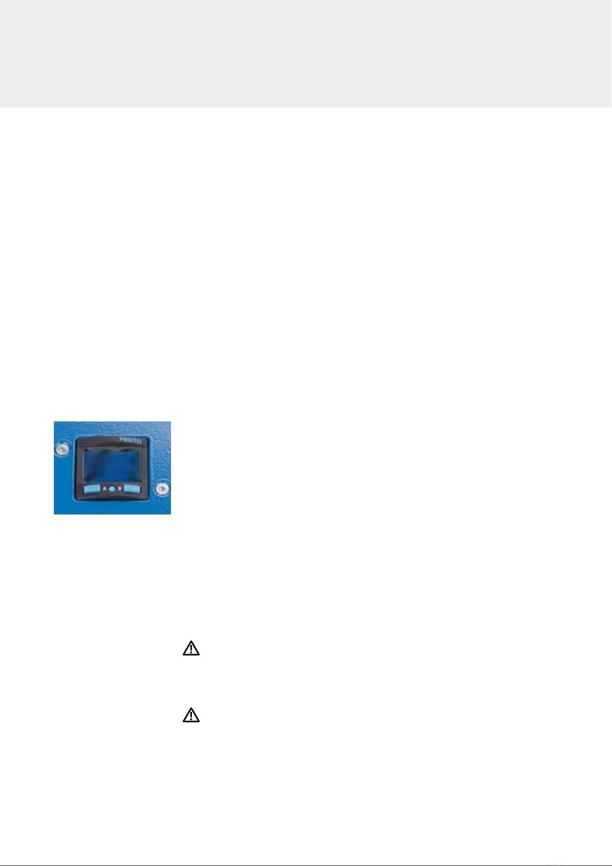
3.6 Pressure generation and monitoring
The heating press has an integrated pneumatic assembly for pressure generation and
monitoring. The pressure hose in the top section is filled when the heating process is
started by pressing start/stop on the control device’s keypad.
Once the heating process is completed, it’s emptied again automatically.
Before the heating process, the display on the pressure regulator shows the current
setpoint. (Fig. 3.6.1)
Factory-adjusted setpoint: 1.2 bar
Maximum setpoint permitted: 2.5 bar
Adjust the pressure required for the splice (see splicing instructions). Proceed as follows:
1. Press the key in the middle underneath the display until “bar” is shown.
2. Adjust the bar setpoint by pressing the arrow keys.
3. Press the key in the middle four times. The new setpoint has now been stored.
The operating pressure (actual value) is displayed during the heating process. This can
increase due to the thermal expansion of the air.
This is normal and requires no intervention by the operative.
Notice
A setpoint that’s higher than 2.5 bars is not permitted, poses a safety risk and will destroy
the heating press.
Notice
The press may only be started if closed.
Fig. 3.6.1
11
3.7 Temperature control/temperature limitation
Some parts of the heating press will get very hot during operation, so the press must only
be touched in specified areas.
Notice
The heating plates must not exceed a temperature of 230°C. If this temperature is exceeded,
it will destroy the heating elements. The power supply will be interrupted.
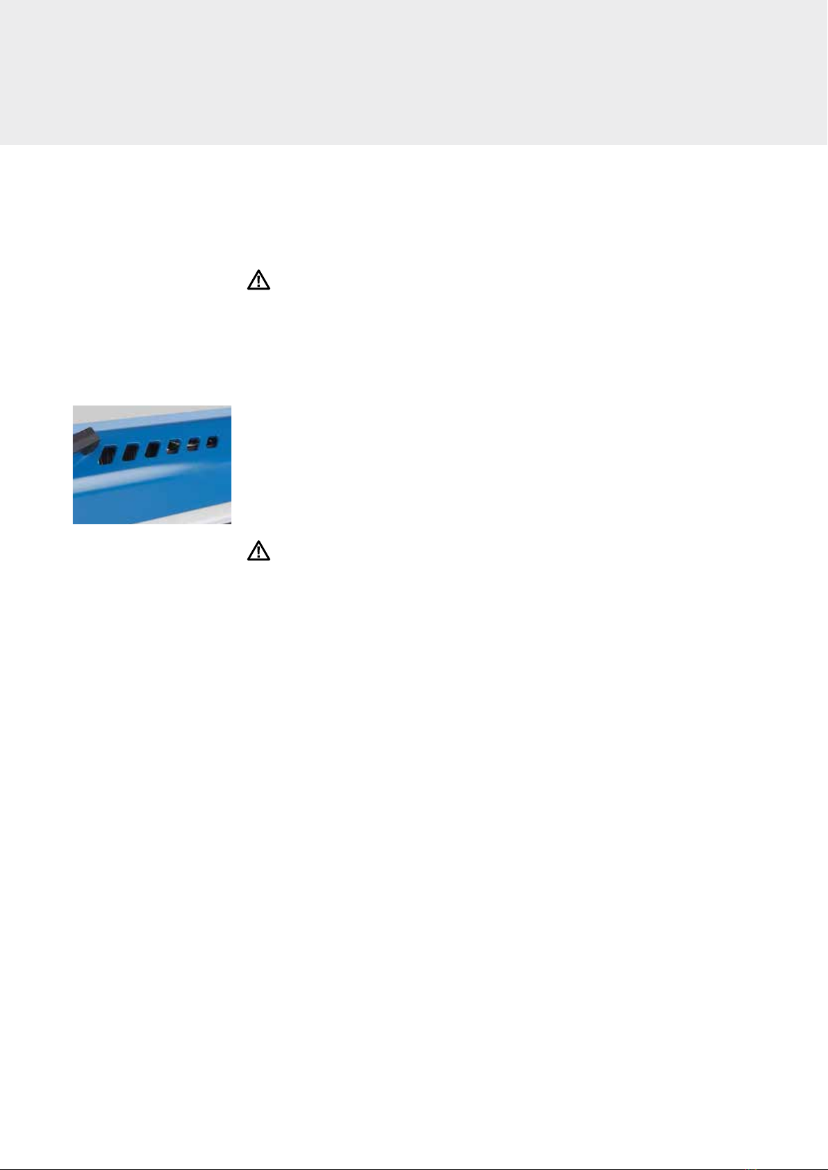
3.8 Air cooling system
The heating plates with the belt material are cooled with air. There are fans in the lower
and top section of the heating press which blow cold air over the heating plates after the
heating process and hold-down time to cool down the press.
In order to have no negative impact on the cooling process, the openings to let the air in
and out must not be covered (fig. 3.8.1).
After reaching the cooling temperature, the fans switch off automatically.
Warning
After cooling, the press can still be hot.
Therefore, only hold the heating press by the handles/ring bolts.
You can only transport the press once it’s cooled down.
Fig. 3.8.1
12
4 OPERATING THE DEVICE
Warning
Check the heating press for damage before you start any
heating process.
Please note:
When making splices, always observe the splicing instruc-
tions for the relevant belt type.
4.2 Inserting the belt
in the heating press
1. Loosen the collar nuts (1) and open out the eye bolts (2).
(Fig. 4.2.1)
2. Lift the top section off the bottom section without
tilting it and place it on the centering bolt (3) on a flat
surface.
3. Remove the upper belt holders (4) on both sides.
Loosen the knurled nuts (5) on the belt holders and
open out the eye bolt. (Fig. 4.2.2)
4. Add the inlays (6) for the belt to be spliced to the press.
Position the laminated fabric inlay (7) in the bottom part
of the press using the positioning hole. (Fig. 4.2.2)
Please note:
There are the following inlays:
– for FLT belts (included)
– for CD, PD1, PD2 belts (accessories).
The following variants of the laminated fabric inlays are
available:
– 30 mm long (for FLT)
– 25 mm long (for CD)
– 18 mm long (for PD1)
4.1 Preparing the heating press
1
4
7
5
6
2
3
Fig. 4.2.1
Fig. 4.2.2

13
5. Prepare the two ends of the belt for splicing.
6. If high impact pressure is to be generated later: Move the
belt holder outward as far as it will go (only for FLT belt
material). To do so, use the belt set screws (8) on the bot-
tom section. (Fig. 4.2.3)
Please note: Higher impact pressure is useful if the cut-
ting edge of the belt material is not very clean/straight.
Notice
In the case of center drive and positive drive types, the
right tooth pitch needs to be made on the splice.
Therefore, precisely adjust the infeed unit according
instructions.
7. Place the soft film (9) or textured mat for the type of belt
over the width of the press on the heating surface.
(Fig. 4.2.3)
8. Use the adjustment aid (10) to adjust the first end of the
belt. Position the adjustment aid based on the perfora-
tions. (Fig. 4.2.4)
Fig. 4.2.3
Fig. 4.2.4
9
10
8

14
10. Insert the first end of the belt (11) in the middle (under-
side at the bottom), attach the belt holder and affix the
inserted belt material with knurled screws (12). (Fig. 4.2.5)
Notice
If the belt is narrower than the nominal width of the
press, the rest of the area to be heated must be lined
with extra material to compensate for the difference. The
belt holders must also be shimmed to prevent bending.
If the heating surface on the bottom part of the press is
not covered with material, pressure distribution will be
poorer. At the same time, there is a risk of overheating or
the material not melting. (Not shown in fig. 4.2.5)
11. Press the end of the belt flush against the adjustment aid
and fix it in its final position by tightening the knurled
screws (12) evenly. (Fig. 4.2.5)
12. Remove the adjustment aid (13). (Fig. 4.2.5)
14. Apply slight pressure to position the second end of the
belt (14) at the front to the first end of the belt and tight-
en the belt holder (15) evenly on both sides using the
knurled screws (16). (Fig. 4.2.6)
15. If required, compress the belt material (only for FLT belt
material) using the belt set screws (17). One turn equals
1 mm of compression. The infeed must be the same on
both sides and can be read accurately on the dial gauge.
(Fig. 4.2.6)
Please note: This is only required if it wasn’t possible
to create any slight impact pressure manually in step 14,
or the edges have the belt edges aren’t neat or straight.
Notice
In the case of center drive and positive drive types, the
right tooth pitch needs to be made on the splice.
Therefore, precisely adjust the infeed unit according
instructions.
16. Place the piece of belt (18) or the shims (19) on both sides
of the area to be spliced. The shims must be 0.1 mm thin-
ner than the belt material. They prevent the bonded
material from seeping out of the sides. (Fig. 4.2.6)
Fig. 4.2.5
Fig. 4.2.6
11
14
13
15
16
18
12
17
19
4 OPERATING THE DEVICE
15
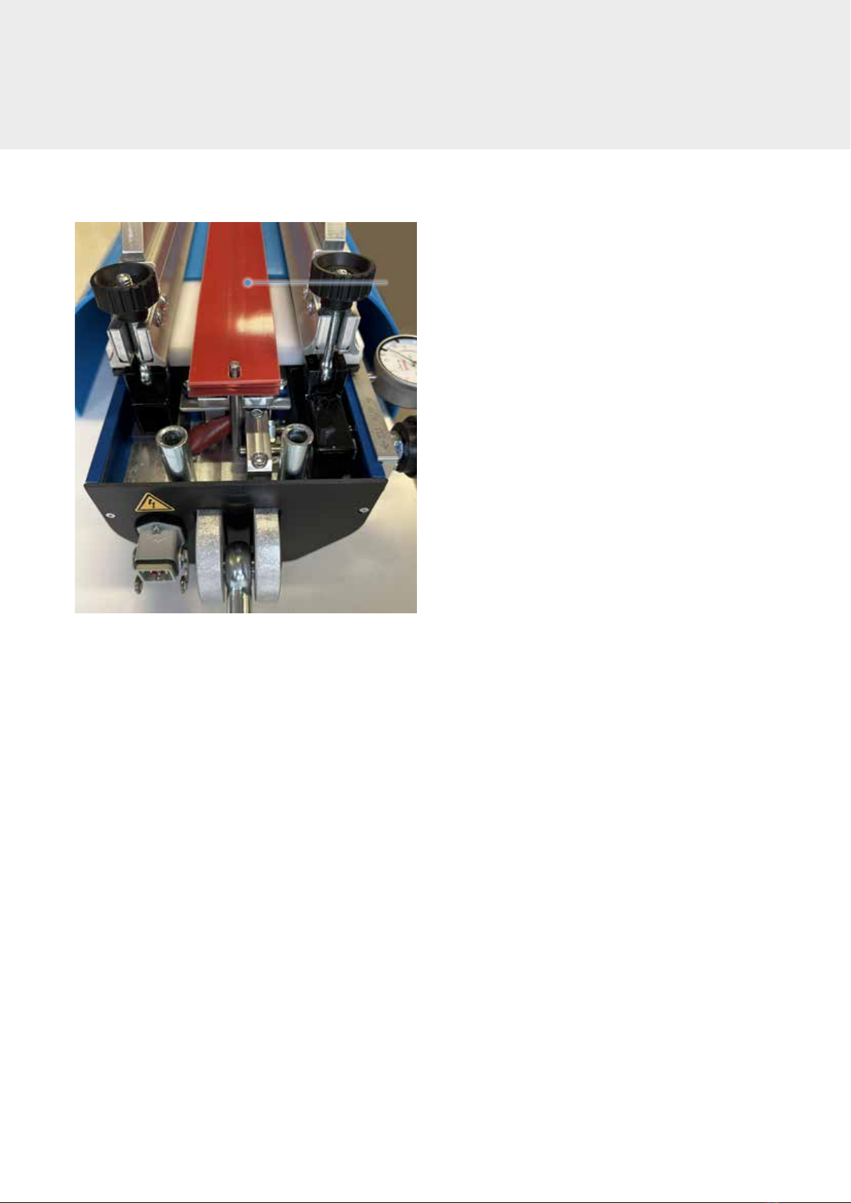
Fig. 4.2.7
17. Depending on the belt type, apply cover material over
the full heating surface over the entire width and posi-
tion and the second laminated fabric inlay (20) on the
cover material. (Fig. 4.2.7)20

16
Warning
There’s a risk of crushing injuries when you close the heating
press.
1. Place the top part of the press on the bottom part of the
press.
The centering bolts (1) on the top section must engage
with the centering holes (2) on the bottom section.
2. Fold up the eye bolt (3) with collar nut and tighten the
collar nut by hand.
4.3 Closing the heating press
1
2
3
Fig. 4.3.1
4 OPERATING THE DEVICE
17
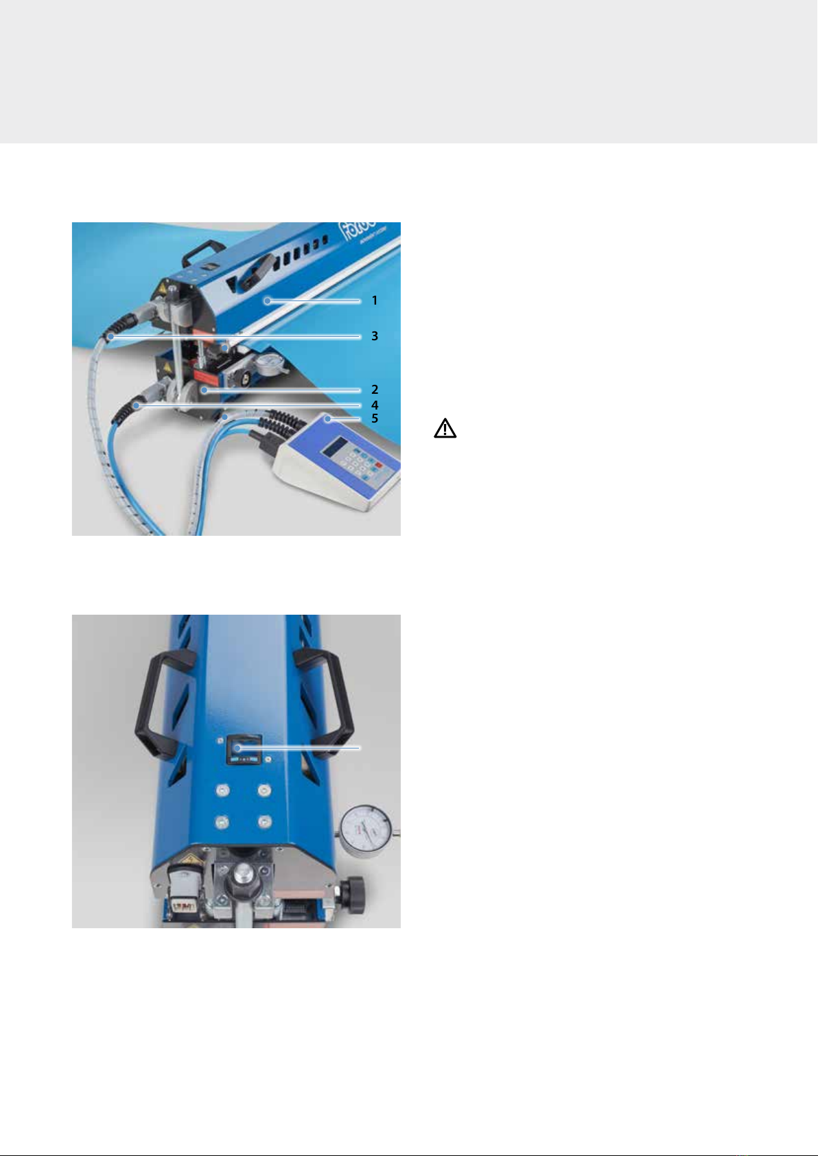
4.4 Connect the heating press to
the mains
1. Connect the top section (1) and bottom section (2) to
the control device (5) with the connecting cables (3/4)
and close the plug lock. (Fig. 4.4.1)
Note:
The plugs are coded with color markings.
They also have different cross-sections and can only be
plugged into the relevant socket on the device.
2. Connect the control device (5) to the power supply.
(Fig. 4.4.1)
Warning
Risk of fire and damage due to overload of the power
supply. Therefore, please read the information stated on
the heating press’s rating plate. If necessary, provide a
separate power connection for the heating press. Only
connect the power supply when the top part of the
press and bottom part of the press are connected to the
control unit.
– Check the air pressure on the pressure regulator (6) and
adjust if necessary. To do so, see section 3.6 on Pressure
Generation and Monitoring (Fig. 4.4.2)
Please note:
The compressed air supply is automatically regulated by
an integrated compressor. The air pressure of 1.2 bar was
set in the factory and may only be changed to a maxi-
mum of 2.5 bar in exceptional cases.
During the heating process, the pressure in the press
may increase due to thermal expansion. This is normal
and requires no intervention by the operative.
1
5
6
2
3
4
Fig. 4.4.1
Fig. 4.4.2
18
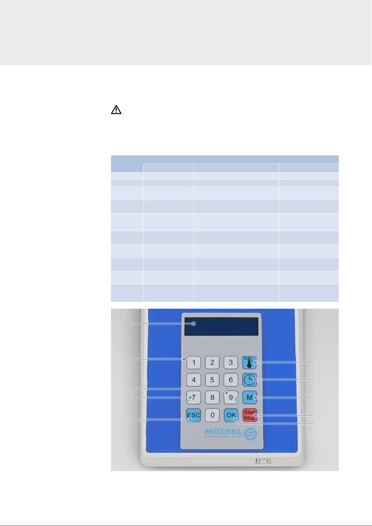
The control device’s controls and displays
4.5 Adjust the control device and heat the splice
Notice
The operative is responsible for entering the right splicing parameters.
1
2
4
5
3
6
7
8
9
10
4 OPERATING THE DEVICE
Designation
Function
Standard Parameter adjustment Pressing procedure
1 Backlit LCD display with 2 x 16 characters
2
(numeric keypad)
no function Value input no function
3no function Selection of the setting function
Selection of the press type no function
4no function Selection of the setting function
Selection of the press type no function
5no function
Exiting the setting function without changing
the parameters or exiting the settings menu.
Cancelling the interruption
request
6no function Invoking the setting function selected Confirming the interruption
request
7Starting the pressing
process no function Interrupting the
pressing process
8Invoking the belt or
press menu no function no function
9Invoking the time menu no function Setpoint display
for the holding time
10 Invoking the
temperature menu no function
Displaying the setpoint- or
actual temperatures in the
Heating plates

19
After switching on, the device checks the plausibility of the internal real-time clock.
If the device detects an error, the user is expected to enter the current time and date.
The time and date are entered using the numeric keys. Press OK to confirm the entry made.
The HPS 2 then checks the entry and expects the user to confirm the set time.
The temperature control device is ready for operation when this screen appears:
In the first line, the current configuration of the HPS 2 appears in the form of a ticker with
the following content:
<Press-type><Belt-type><AdV><[Set temperature of the top heating plate] – [F/V]>
<[Set temperature of the bottom heating plate]-[F/V]><hold-down time -[F/V]>
F means: The value of the parameter equals the value stored in the list of belt types
V means: The user changed the value of the parameter.
The progress bar in the second row moves continuously from left to right.
Operating the device
The temperature control device is switched on when the heating press is connected to the
mains. A welcome text and the current firmware version appears on the device’s display.
(HPS2 > heating press control 2)
Please note:
If the software detects an error, an error message appears (see page 27).

20
This menu item can be switched off
by the HPS2 configuration program.
Select the belt type, press type or belt type new
Pressing the M key opens the menu concerned.
The menu structure is shown in the figure on the left.
The <belt-type>, <press-type> or belt type new> functions can be selected by pressing the
7 or 9 keys and opened by pressing OK.
4 OPERATING THE DEVICE
Table of contents
Languages:
Other Forbo Power Tools manuals


