Force USA JX-DS926 User manual
OWNER’S MANUAL JX-DS926
Multi-Utility 205lb Home Gym with Lever- Press and FID Utility Bench Included
CAUTION!
Read all precautions and instructions in this manual before using this equipment.

、
This exercise equipment is built for optimum safety. However, certain precautions apply whenever you
operate a piece of exercise equipment. Be sure to read the entire manual before you assemble, operate
or use this equipment.
Assembly
• The product must be installed on a stable and level
surface.
• Assemble the item as close to its final position
(in the same room) as possible.
• Make sure you have enough space to layout the
parts before starting.
• Keep children and animals away from the exercise
area, small parts could pose a choking hazard if
swallowed.
• Dispose of all packaging carefully and responsibly.
• Check you have all the components and tools
listed in the parts list, bearing in mind that, for
ease of assembly, some components are pre-
assembled.
• The assembly of this equipment is best carried out
by 2 or more people.
Use
• It is the responsibility of the owner to ensure that all
users of this product are properly informed as to how
to use this product safely.
• This product is intended for domestic use only.
Do not use in any commercial, rental, or institutional
setting.
•Use the equipment only for intended use, as
described in this manual. Do not use attachments not
recommended by the manufacturer.
• Keep this equipment indoors, away from moisture
and dust. Do not put the equipment in a garage,
outbuilding, covered patio, or near water.
• Your product is intended for use in clean dry
conditions. You should avoid storage in excessively
cold or damp places as this may lead to corrosion
and other related problems that are outside our
control.
• Keep unsupervised children away from the
equipment.
• Parents and others in charge of children should be
aware of their responsibility because the natural play
instinct and the fondness of experimenting of
children can lead to situations and behavior for which
the training equipment is not intended.
• If children are allowed to use the equipment under
supervision, their mental and physical development
should be taken into account. They should be
controlled and instructed to the correct use of the
equipment. The equipment is under no
circumstances suitable as a toy.
• Disabled persons should not use the equipment
without a qualified person or doctor in attendance.
This product is not suitable for therapeutic
purposes.
• Always wear appropriate workout clothing when
exercising. Do not wear loose or baggy clothing, as
it may get caught in the equipment. Wear trainers
to protect your feet while exercising.
•Do not place any sharp objects around the
equipment.
• Keep hands away from all moving parts.
• If any of the adjustment devices are left projecting,
they could interfere with the user’s movement.
• Before using the equipment to exercise, always
perform stretching exercises to properly warm up.
• Only one person at a time should use the
equipment.
• A spotter is recommended during exercise.
• If the user experiences dizziness, nausea, chest
pain, or other abnormal symptoms stop the workout
and seek immediate medical attention.
• Injuries to health may result from incorrect or
excessive training.
• This product is suitable for a maximum user weight
of: 120kg.
Warning: Before beginning any exercise program, consult your doctor. This is especially important
for people over the age of 35 or persons with pre-existing health problems or those who have not
exercised for a period of time. You MUST read all instructions before using any fitness equipment. We
assume no responsibility for personal injury or property damage sustained by or through the use of this
product.
Important – Please read fully before assembly or use
Safety information
1
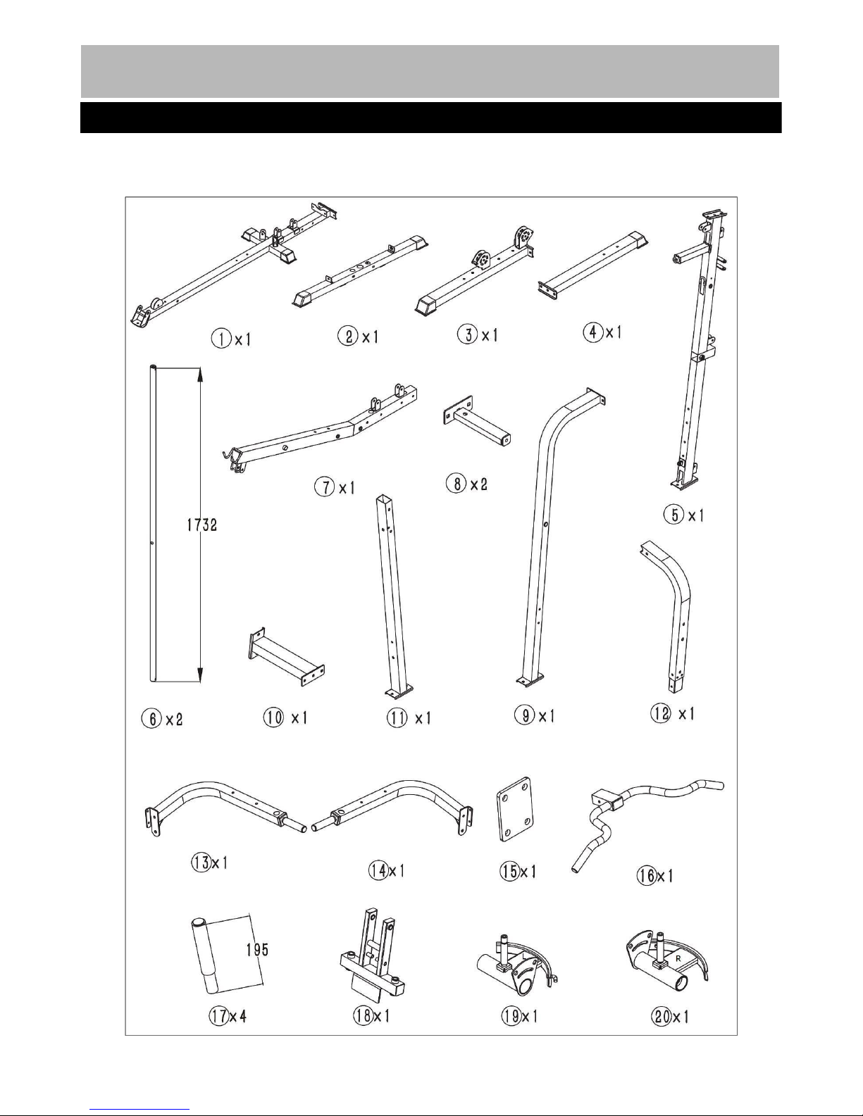
Note: Some of the smaller components may be pre-fitted to larger components. Please check carefully
before contacting us regarding any missing components.
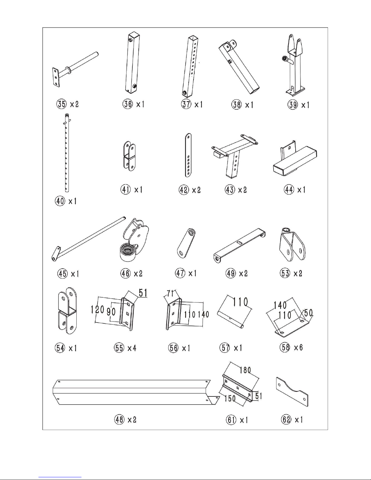
Components - Parts
Please check you have all parts listed below
2

2
3
4

5
6
6
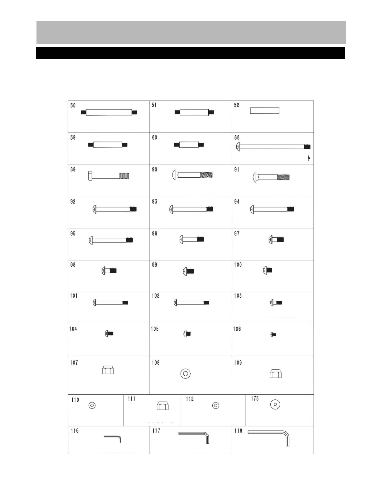
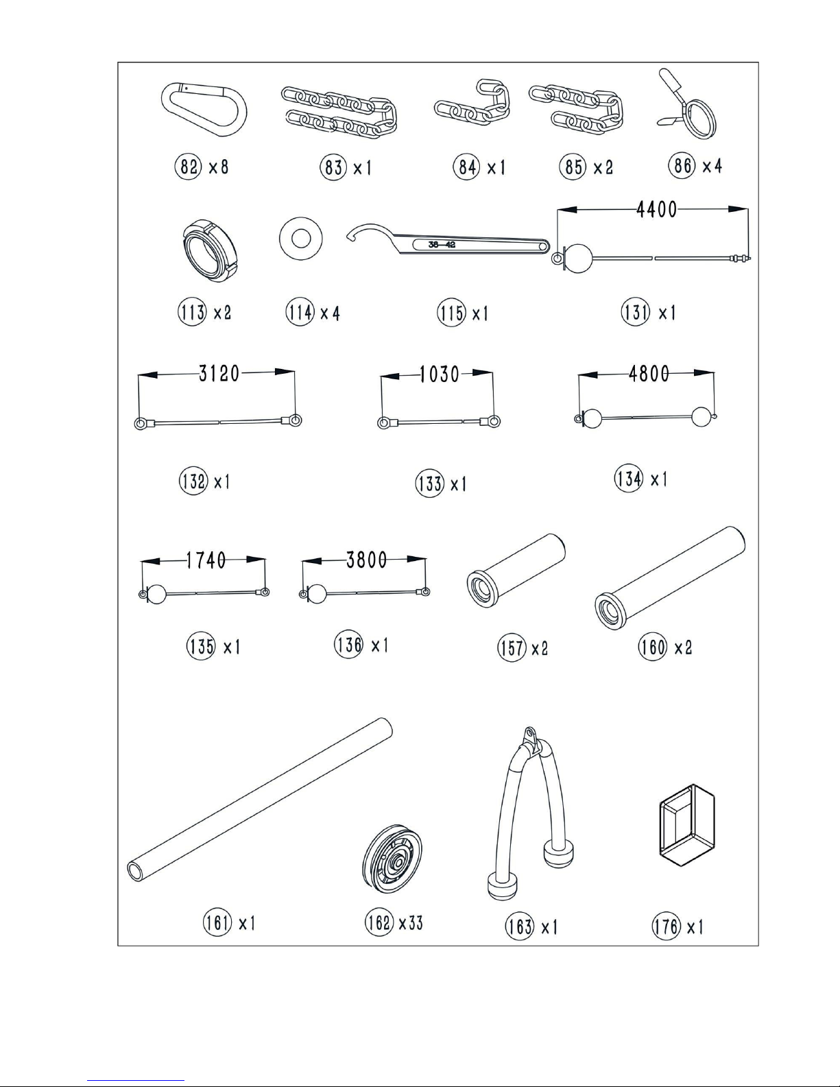
Note: The quantities below are the correct amount to complete the assembly. In some cases more
hardware may be supplied than are required. Some of the fixings are pre-fitted to the larger components.
Please check carefully before contacting us regarding any missing fixings.
Components - Fixings
Please check you have all parts listed below
7

Assembly Instructions
Insert 2 pcs guide rods (6#) into the holes of the Rear Stabilizer(2#) separately and tighten them with 2
pcs M10*20 Allen Bolt(99#) and 2pcs φ10 washers(110#).
Slide the 2pcs rubber bumper(81#) along the guide rods (6#) separately.
Attach the Main base Frame(1#) to the Rear Stabilizer(2#) as the diagram shows and tighten them with
2pcs M10*70 carriage bolt(91#),1pc bracket(61#),2pcs φ10 washers(110#) and 2pcs M10 Aircraft
nuts(109#) .
Step 1
8
Step 2
9
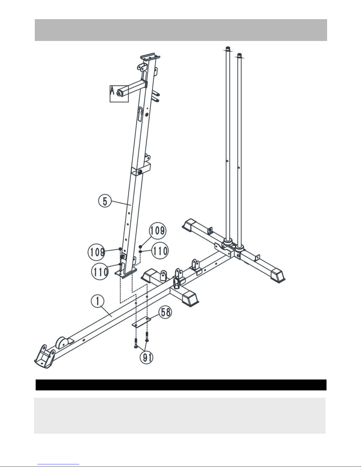
Assembly Instructions
Attach the front vertical frame(5#) onto the base frame(1#). Carefully align the holes and secure them
with 2pcs M10*70 carriage bolt(91#), 1 pc bracket(58#),2pcs φ10 washers(110#) and 2pcs M10 Aircraft
nuts(109#) .

Assembly Instructions
A.Place the long bend frame(9#) onto the right stabilizer (3#), Carefully align the holes and secure it with
2pcs M10*70 carriage bolt(91#), 1 pc bracket(58#),2pcs φ10 washers(110#) and 2pcs M10 Aircraft
nuts(109#) .
B.Place the shorter support(39#) onto the right stabilizer(3#), Secure it with the same way in A.
C.Place the lower vertical frame(11#) onto the left stabilizer(4#),Secure it with the same way in A.
D.Attach the left stabilizer(4#) and right stabilizer(3#) to the base frame (1#) together as the diagram
shows,Carefully align the holes and secure them together with 2pcs M10*90 carriage bolt(90#),2pcs φ10
washers(110#) and 2pcs M10 Aircraft nuts(109#) .
Step 3
10
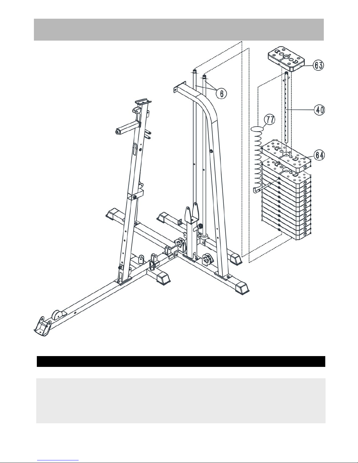
Assembly Instructions
Step 4
11
Place 13pcs weight plate(64#) along the guide rods(6#) from the top to the bottom, Insert the Selector
Rod(40#) into the center hole of the weight plates. And then place the weight stem(63#) again.
Select the desired weight with the selector pin(77#) during the exercising.

Assembly Instructions
A.Place the Upper Frame(7#) onto the Front Vertical Frame(5#), Align the holes and secure them with
2pcs M10*90 carriage bolt(90#), 1 pc bracket(58#),2pcs φ10 washers(110#) and 2pcs M10 Aircraft
nuts(109#) .
B.Attach the 2pcs Fixing frame (8#) to the end of the upper frame (7#) as the diagram shows,Secure
them with 2pcs M10*70 carriage bolt(91#),2pcs φ10 washers(110#) and 2pcs M10 Aircraft nuts(109#) .
C.Attach the 2pcs weight stack cover bracket(49#) to the 2pcs fixing frame(8#) and 2pcs guide
rods(6#),Secure them with 2pcs M10*20 Allen bolt(99#) and 2pcs φ10 washers(110#) .
Step 5
12

Assembly Instructions
A.Attach the upper bend frame (12#)into the lower frame(11#),Secure them together with 2pcs M10*90
carriage bolt(90#), 2 pc bracket(55#),2pcs φ10 washers(110#) and 2pcs M10 Aircraft nuts(109#) .
B.Place the connection frame(10#) between the upper frame(12#) and upper frame(7#), Secure them
together with 4pcs M10*70 carriage bolt(91#),4pcs φ10 washers(110#) and 4pcs M10 Aircraft
nuts(109#) ,1pc bracket(56#) as the diagram shows.
Step 6
13
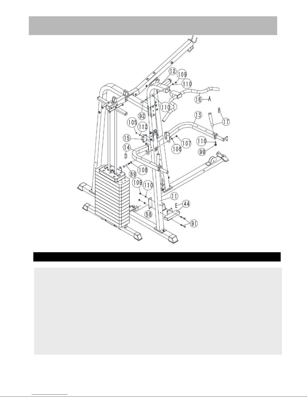
Assembly Instructions
Step 7
A. Attach the foot support(44#) to the lower frame (11#) and secure them together with 2pcs M10*70
Carriage bolt (91#),1 pc bracket(58#),2pcs φ10 washer(110#) and 2pcs M10 Aircraft nuts(109#) .
B.Attach the left & right dip support(13#&14#) to the lower frame (11#), Secure them with 1pc M12*95
Hex bolt (89#),2pcs φ12 washers(108#),1pc M12 Aircraft nut(107#).4pcs M8*10 Allen bolt (105#),4pcs
φ8 washer (112#)1 pc 4-hole bracket(15#).
C. Attach the chin up bar(16#) to the end of the upper bend frame (12#)as the diagram shows, and
secure them together with 1pc M10*85 Allen bolt(92#),1pc φ10 washer(110#) and 1pc M10 Aircraft
nuts(109#) .
D.Insert the 2pcs vertical handle(17#) into the hole of the the left & right dip support(13#&14#),and
secure them with 1pc M10*20 Allen bolt(99#),2pcs φ10 washer(110#).
14
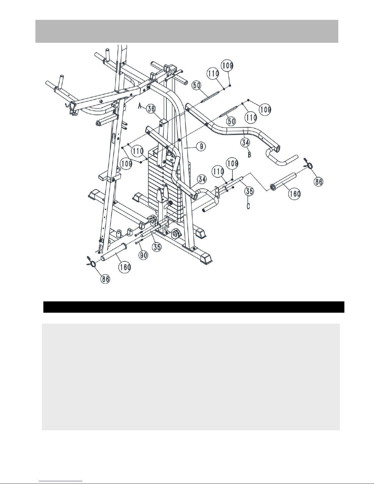
Assembly Instructions
Step 8
A.Attach the 2pcs weight plate holders(35#) to the Long bend frame (9#),Secure them with 2pcs
M10*90 carriage bolt (90#),2pcs φ10 washer(110#) and 2pcs M10 Aircraft nuts(109#) .
B.Attach the 2pcs long sleeve(160#) to the weight place holders(35#),and then attach attach the 2pcs
collar(86#) again as the diagram shows.
C.Attach the 2 pcs lifting arm(34#) to the bend frame(9#), Secure them with 1 pc axle(50#),2pcs φ10
washer(110#) and 2pcs M10 Aircraft nuts(109#) .
D.Secure the another lifting arm(34#) to the adjustment frame(36#) with the same way in C.
15
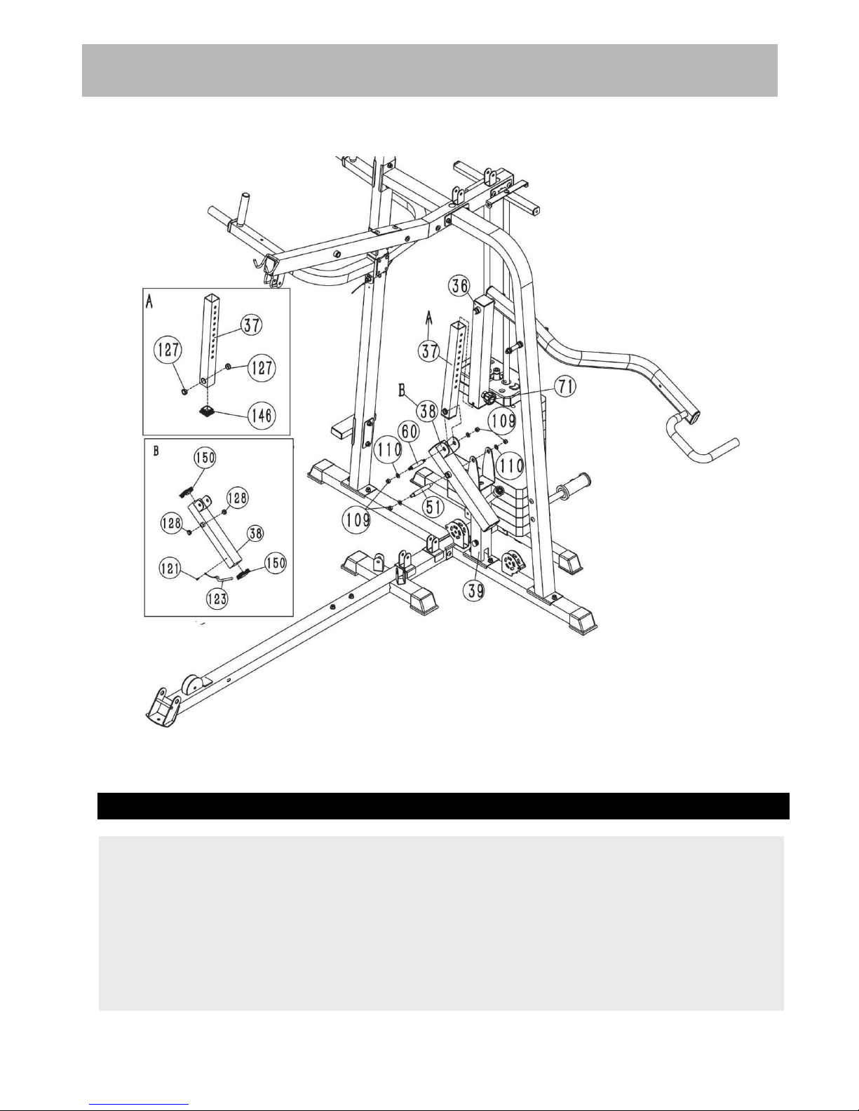
Assembly Instructions
Step 9
Attach the connection frame (38#) to the shorter support(39#) and secure them with 1pc axle(51#),2pcs
φ10 washer(110#),2pcs M10 aircraft nut(109#).
Insert the inner frame(37#) into the adjustment frame(36#) and select the height with the lock knob
(71#).
Attach one end of the inner frame(37#) to the connection frame (38#) and secure them with 1pc
axle(60#),2pcs φ10 washer(110#),2pcs M10 aircraft nut(109#).
16
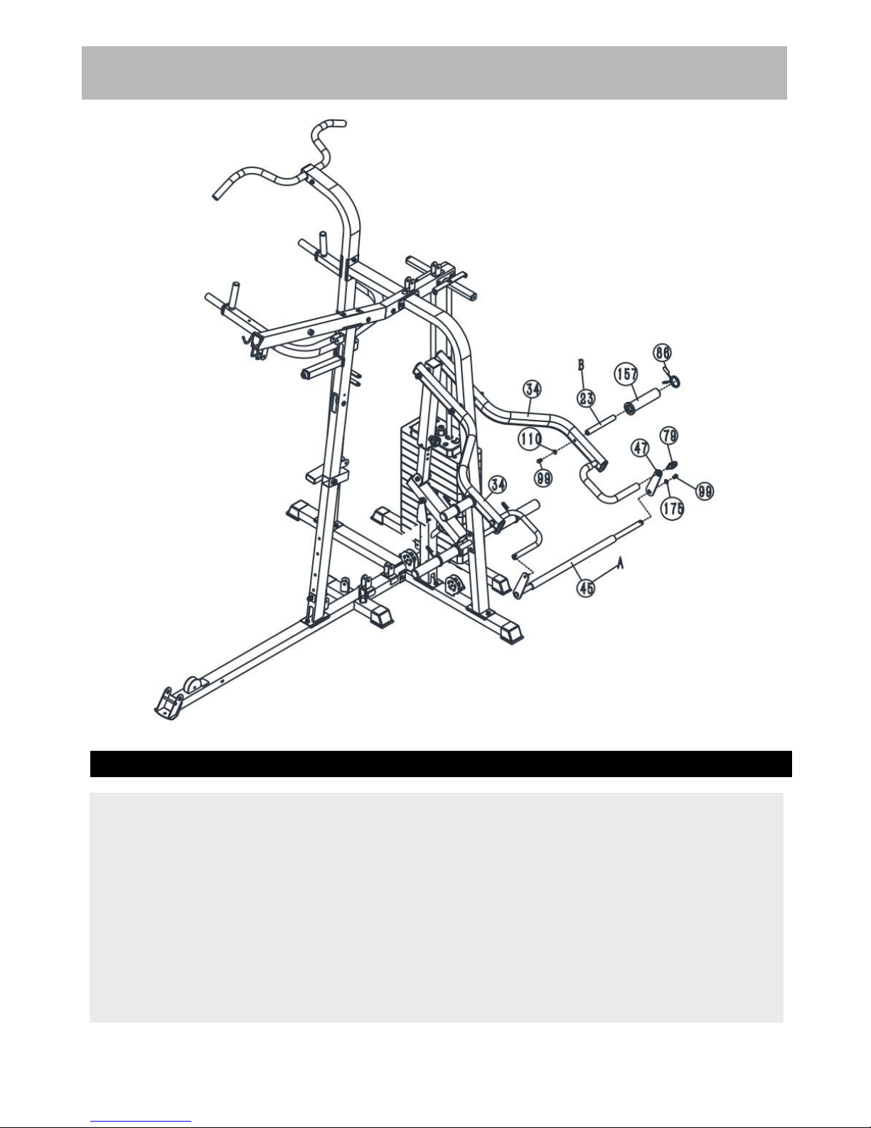
Assembly Instructions
Step 10
Attach the weight plate holder(23#) to the lifting arm(34#) ,and secure them together with 1pc M10*20
Allen bolt (99#) and 1pcs φ10 washer(110#) .
Attach the sleeve(157#) to the weight plate holder(23#) and then attach the collar (86#).
Repeat the same way to install another one.
Attach one end of the push bar (45#)to the lifting arm(34#),Attach another end of the bend
frame(34#) with 1pc M10*20 Allen bolt(99#),1pc big φ10 (175#),1pc swivel bracket(47#) and 1pc M16
lock pin (79#).
17
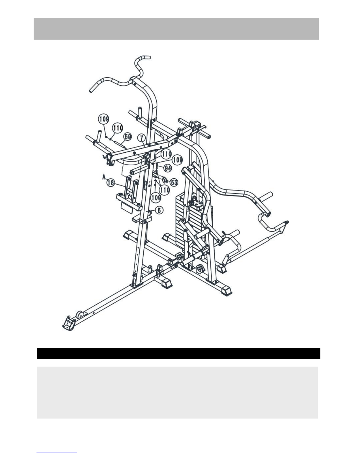
Assembly Instructions
Step 11
Attach the Front Press Frame(18#) to the Upper Frame(7#), Secure them with 1pcs axle(59#),2pcs φ
10 washer(110#)and 2pcs M10 Aircraft nut (109#).
Attach the swivel pulley bracket(53#) to the front vertical frame (5#), secure them with 1pc M10X65
Allen bolt(94#),2pcs φ10 washers(110#)and 2pc M10 Aircraft nuts(109#) .Repeat the same way to
install another swivel pulley bracket.
18
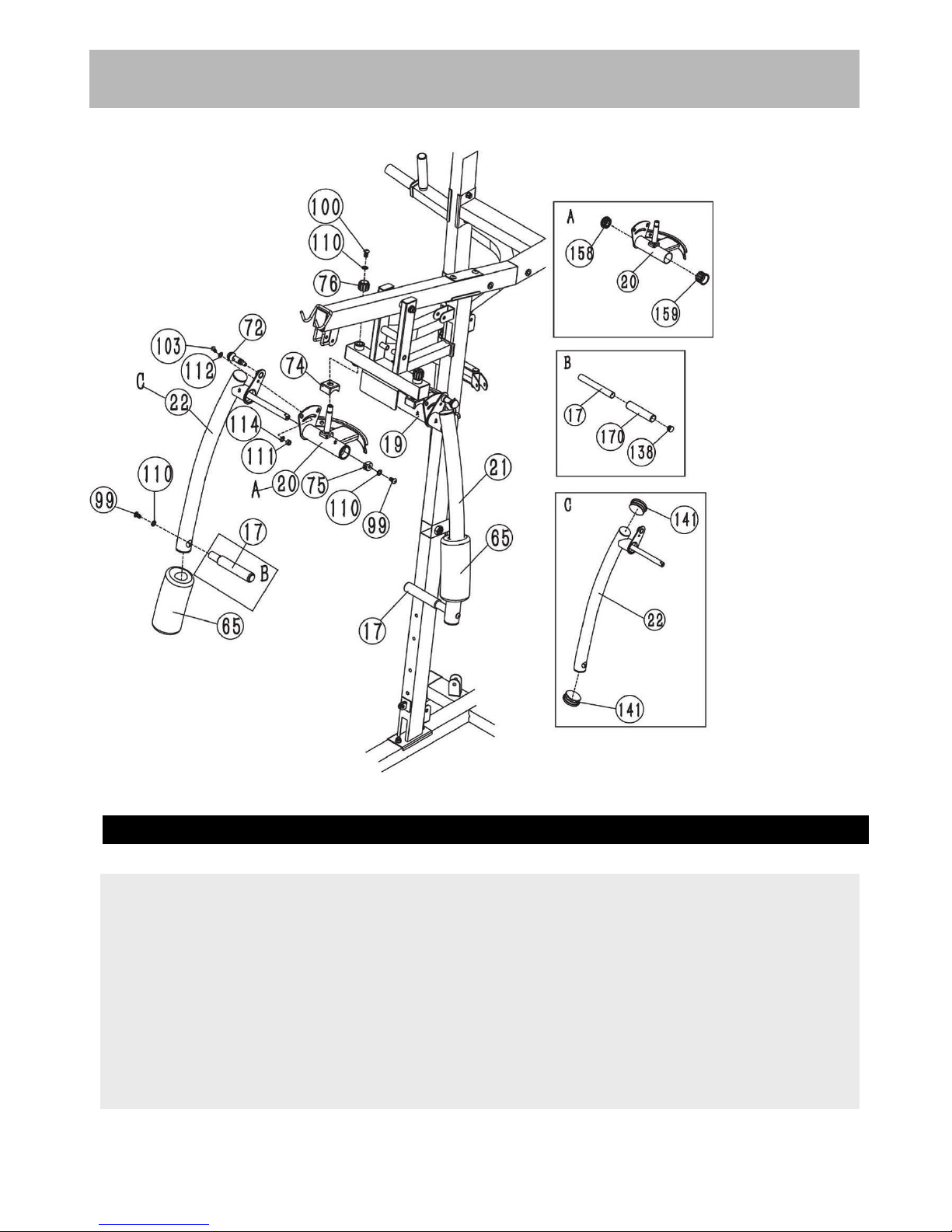
Assembly Instructions
Step 12
Attach the plastic cover (74#) as the diagram shows,Attach the right butterfly adjustment frame (20#)
through the hole of the front press base (18#),Secure it with 1 pc lock ring(76#),1pc φ10 washer
(110#)and M10*16 Allen bolt(100#).
Attach the right butterfly frame(22#) to the right butterfly adjustment frame(20#) as the diagram shows,
and secure them with 1pc M8*22 Allen bolt(103#),1 pc φ8 washer (112#),1pc plastic washer(114#),
1pc M8 aircraft nut(111#).1pc spacer(75#),1pcφ10 washer(110#)and 1pc M10*20 Allen bolt(99#).
Push 1pc butterfly foam roll(65#) as the diagram shows.Attach the handle(17#) into the hole of the
butterfly and secure it with 1pc M10×20 Allen Bolt (99#), 1pc φ10 washer(110#).
Repeat the above same way to install the left one.
19
Table of contents
Other Force USA Home Gym manuals


