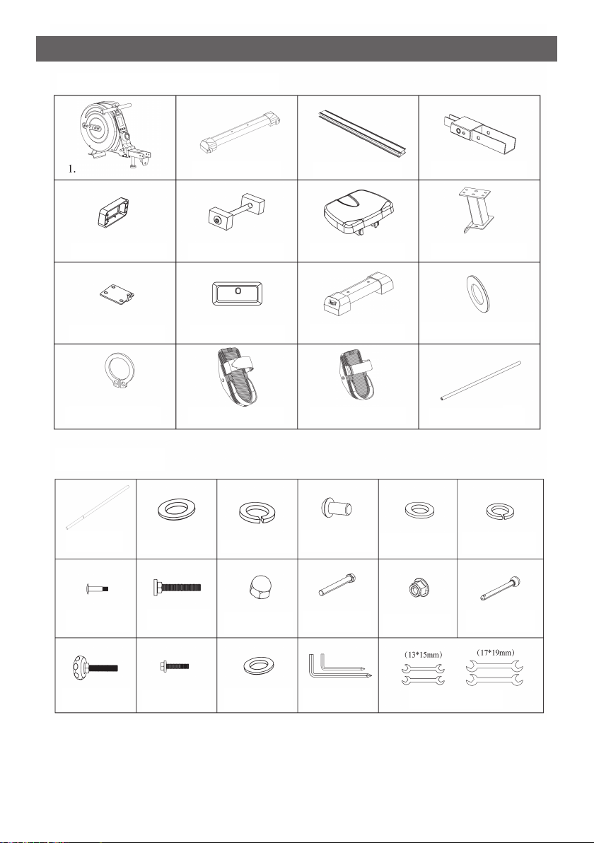
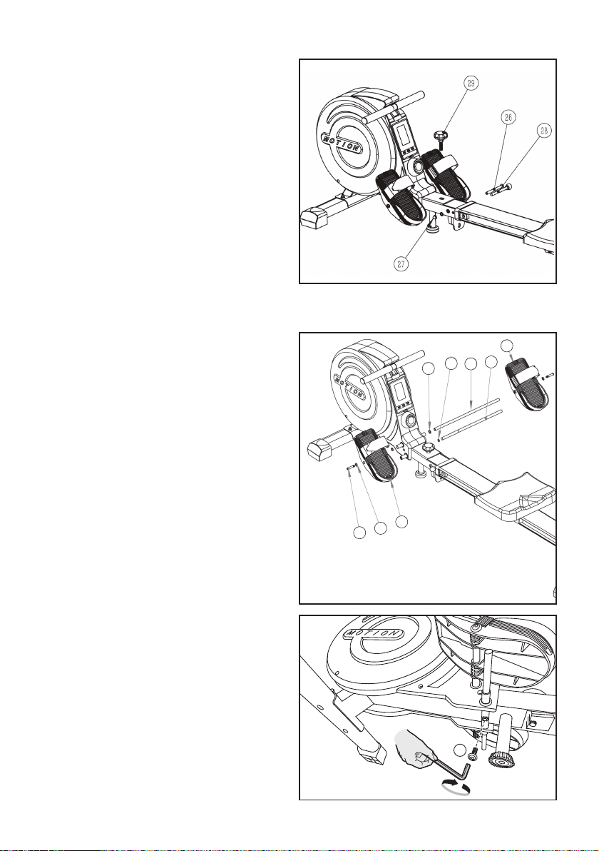
Step 3: Assemble the seat and rear of the rail
For the step, please prepare a lock bolt set
(No.6), the seat (No.7), rear support(No.8).
connecting shect (No.9), rear rail cover
(No.10), four M8*16mm bolts (No.20), four
split washers (Nc.21), four flat washers
(No.22), M5*16 bolt (No.23), and two Allen
wrenches (No.32).
lnstall the seat to the rail. Attach the rear
support under the rail. Inset the connectint
sheet into the open of the rail.
Attention: the upturned piece should be
outward. Screw two M8*16mm bolts, two split washer, and two flat washers under
the rail.
And then screw more two M8*16mm bolts, two split washer, and two flat washers
into the open of the rail to fix the connecting sheet.
Disassemble one side of the lock bolt set. Inscrt to the horizontal hole of the rail and
screw the rubber pad and the lock bolt back. Rotate the rubber pads upright to fix.
Cover the rear rail cover and screw the M5*16 bolt to fix.
Step 4: Assemble the rear foot pipe
Attach the rear foot pipe (No.11) to the
rearsupport.
Screw two M10*55mm carriage bolts
(No.24). two M10 flat washer (18) and two
M10 acornnuts ( No.25) by using the
open-end wrench (No.33).
Before assembling ensure you will have
enough space around the item.
Use the supplied parts and hardware for the
assembly. Before assembling please check
whether all the required parts have been
supplied as per the exploded drawing on
the opposite page.
-7-