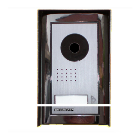
Forematic i 460 iPSO User manual

- 1 -
i
460 ip intercom Installation manual doc. K42
doc. K42
iss V1.1
i
460 iPSO installation manual
Specifications
Supply 12-15Vdc
Standby 140mA
Camera 10Mega pixel
WiFi band 2.4GHz
Dims 210h x 105w x 32d
Protection IP55
Temp’ -25°C to 65°C
Keypad 40 codes 2-6 digit
Relay 1A, 30Vac SPCO
Period 0-99 secs on time
Video IP intercom
WiFi wireless or ethernet wired
Connects to 4 phones
40 code keypad door release
Snapshot & video clip memory
Monitor mode to view
3G/4G roaming connection
iOS Android
1 Description
iPSO is an IP (internet protocol) call station that connects by WiFi or
wired connection to a home router. Other devices connected to the
same router, such as laptops, smartphones or tablets may receive
video calls from the iPSO panel via a resident APP.
2 Scope of operation
2.1 Panel
The panel connects to a home hub in one of two ways. The easiest
way is to connect to a WiFi equipped router. Range is typically 40m
indoors, or 80m outdoors. If WiFi reception is not possible, an
ethernet cable connection can be made. Panels need to be
powered locally, often from gate control panel. An output can
operate the gate controller or a door release.
2.2 Receiver devices
Any WiFi enabled device with communication ability can be set to
receive calls from the iPSO, such a tablet, smartphone, or laptop.
Up to four devices can be set to receive a call via a free APP.
Android or iOS APPs are downloaded free from their respective
stores. These are currently the only two APPs.
2.3 Connection modes
A home hub is the panel’s connection to internet cloud. From there,
the server is able to find and connect to devices outside the home.
Smartphones, laptops or tablets can be reached when connected to
a public WiFi network, such as a café or shop, including outside the
country. Phone devices with 3G or 4G data roaming enabled allow
the device to be connected wherever mobile service is available.
3 Connection by APP
A panel can call up to four smartphones. The identity of each phone
or tablet must be mapped to the call panel identity. A programme
on the cloud server stores IP addresses (device ID’s) of devices that
are to be connected, allowing the smart device to be found outside
the range of the home hub.
Compatible devices
The Apple APP is compatible with iOS 7 and more recent, taking in
devices iPhone 4S, iPhone 5, iPhone5S, iPad 2, iPad 3, iPad 4, iPad
Air, iPad Mini 1, iPad Mini 2 with activated Apple-ID.
The Android APP works with Android 4 and more recent. Minimum
requirement is a dual core 1GHz processor or faster with activated
Google Play Account.

- 2 -
i
460 ip intercom Installation manual doc. K42
4 Configuring the panel
The iPSO panel can make a WiFi connection to the router, or can be
wired with an Ethernet cable (for which an adaptor is provided). The
panel uses the standard 2.4GHz WiFi band. Be sure the panel antenna
is connected. Check router frequency and range if there’s a problem.
Restoring factory settings
The panel needs to returned to factory setting if a router is changed.
Power down the panel, press and hold the call button, then power up
again. Keep holding the call button for around 45 seconds, until the
LED flashes and you hear a short beep, then release the button.
Download the APP
The “ControlCam” APP can be downloaded from either the Apple or
Android store. Search for it (4.2). It is free to download.
Find the iPSO WiFi signal
Open the phone system settings, then select the WiFi menu. Look for
a WiFi signal on the screen starting LIDxxxx, and then click on it.
5a …by an iOS device
Search for the panel WiFi (5.1 & 5.2)
Open the ControlCam APP on you phone. Select “Add a New Device”
followed by “Start Configuring”. Select your router’s WiFi network
and enter the password normally printed on the back of the router.
Select the panel to be configured (5.3)
Click on the GID number of the panel on the search list. This number
is also printed and as a QR code on the rear of the panel. It can be
entered manually. Enter user name & password, then click OK.
Device ID “Front Door” a name chosen by user
GID aw14d62154 copied from label or paired
User admin default is admin, change later
Password 1234 default is 1234, change later
Enabling calls (5.4)
Click ‘●●●’ on the top right corner and click ‘ON’ for call panel
call-in options. This device is ready.
4.1
4.2
4.3
4.5
5.2
5.1
5.3
5.4

- 3 -
i
460 ip intercom Installation manual doc. K42
7User instructions
Answering a call
When a call is received, the ‘phone will alert the user with the call
tone set in your ‘phone, and the picture will pop up. Press either the
“Accept” to speak to the caller, or press “Decline” to stop the alert.
If you accept the call you can hear the caller, but need to hold the
mic key for your voice to be heard. Release to listen to the
caller.
Image captur and video recording
During a call, a single snapshot can be saved by pressing the
the icon on the screen. Likewise, the and icons may
be used to start and stop recording a video clip. The file will be
found on your device picture memory.
Monitoring the camera
Any device with the APP loaded can connect with the camera. Load
and register the APP in the normal way. When the APP loads, it will
show the live camera picture. You may also listen to the panel using
and speak through it with icons.
Door release code
The door release relay can be operated any time your phone is
connected to the call panel, whether in answering a call, or
connecting by opening the APP. To unlock the door, enter the 4
digit code on the soft keypad, then close the APP.
The code can be changed on the APP by authorised ‘phones. Click
‘●●●’ on the top right corner of your device. Click ‘OFF’ in outdoor
call in option. Click “unlock password setting” to get the edit screen.
You will need to enter the old release code (password) and the new
release code. Click “setting” to exit.
5b … by an Android device
Search for the panel WiFi (5.1 & 5.2)
Open the ControlCam APP on you phone and click “Enter now”. Select
“Add a Device” followed by “Add a New Device”. The phone searches
for WiFi signals, then displays a list. Panel numbers begin GIDxxx. This
number is also printed and as a QR code on the rear of the panel, and
can be entered manually later. Click the panel ID.
Now click “Start Configuring”. Select your router’s WiFi, and enter its
password, normally printed on the back of the router. Wait 100 secs.
“Configuration is successful, please add the device to the phone”.
Click OK to confirm. Now enter user name & password….
Device ID “Front Door” a name chosen by user
GID aw14d62154 copied from label or paired
User admin default is admin, change later
Password 1234 default is 1234, change later
Click OK to confirm data. Click ‘●●●’ on the top right corner and
click ‘ON’ in the call-in options. This device is ready.
6Keypad programming
Mastercode reset
This procedure allows a new mastercode to be set. It does not change
existing access codes or the system password. Switch off the power,
then power up again while holding the * button. Release * and press
* once more. Enter your new mastercode the same length as the old
mastercode. Another long beep indicates the mastercode is accepted.
Factory reset
This procedure clears all the access codes, resets the relay time to 1
sec, and resets the mastercode to 1234. Follow the master-code reset
above, but using the # button instead of the * button.
Programming examples
The codelock is programmed using a codelock mastercode. It can be
set from 2 to 6 digits long. Mastercode is denoted in the examples
below by xxxx. Five examples are shown.
- Press * xxxx ‘Beep’ (enter programming mode)
--1--------------------------------------------------
- Press 99 ‘Beep’ (enter memory 99)
- Press 4‘Beep’ (sets code length to 4 digits)
--2--------------------------------------------------
- Press 00 ‘Beep’ (enter memory 00)
- Press 03 ‘Beep’ (sets relay time to 3 secs)
--3--------------------------------------------------
- Press 34 ‘Beep’ (enter memory 34)
- Press 2580 ‘Beep’ (set code in memory 34 to 2580)
--4--------------------------------------------------
- Press 37 ‘Beep’ (enter memory 37)
- Press * ‘Beep’ (delete code in memory 37)
--5--------------------------------------------------
- Press #‘Beep’ (delete code mode)
- Press 1397 ‘Beep’ (delete code 1397 from any memory)
----------------------------------------------------
- Press *‘Beep’ (exit programming)
To exit programming, press * key, or leave for 30 secs.
Forematic
9 Vanalloys Estate QPF14-210
Stoke Row
Henley RG9 5QW www.forematic.com
Declaration of Conformity
We hereby declare, that roller door opener F-210 has been manufactured
in accordance with the following standards or normative documents
EN 60335-2-95: 2004
EN 60335-1/A13: 2008/A2: 2006
EN 62233: 2008
EN 61000-3-2: 2006, + A1: 2009 +A2: 2009
EN 61000-3-3: 2008
EN 55014-1: 2006 +A1: 2009 EN 55014-2: 1997 +A2: 2008
EN 50371: 2002
In accordance with the provisions of the following directives
98/37/EC Machinery Directive with amending directives
2006/95/EC LV Directive
2004/108/EEC EMC Directive
1999/5/EC R&TTE Directive
23.03.2015 –FOREMATIC
9 Vanalloys Estate, Stoke Row, Mr H WYNN JONES
Henley RG9 5QW, United Kingdom Director
Table of contents
Other Forematic Intercom System manuals
