Forematic 502 Quick start guide

Page 1
502 VIDEO DOOR PHONE
Safety & Operating Instructions
Please read through these instructions thoroughly before use and retain for future reference.
- Contents -
1 User guide
1.1 Safety instructions Page. 1
1.2 Guide to the equipment Page. 2
1.3 Operating instructions Page. 2
2 Installation
2.1 Preparation & contents Page. 3
2.2 ables required Page. 3
2.3 Installing the screen Page. 4
2. Installing the camera panel Page. 4
2.5 ompleting the installation Page. 5
2.6 ommissioning Page. 6
3 Care and maintenance
3.1 Daily maintenance Page. 6
3.2 Warranty Page. 6
3.3 Trouble shooting Page. 7
Appendices
App.1 Wiring diagram Page. 8
App.2 Technical characteristics Page. 9
App.3 Equipment upgrades Page. 10
- 1.1 Safety Instructions -
This product is designed for moderate climates. Do not
use in high humidity, dusty, or dirty environments. The
camera panel should be mounted with its rain hood
away from pouring water. Never use a pressure washer
near the camera panel. Trim back vegetation around
the camera panel to avoid dripping and lens abrasion.
Facing extreme sunlight will reduce picture quality.
Screens should be wall mounted on the bracket
provided. Do not allow curtains or clothing to cover the
ventilation holes behind the screen. Do not allow the
screen to operate near steam, moisture, naked flames
or extreme heat as found in some kitchens areas or in
bathrooms. Avoid extremely bright locations which may
affect the screen image.
Never disassemble components. Do not overload
power sockets, and remove the power if the system is
not to be used for long periods. Do not drop or apply
physical shocks. Do not expose units to acid oxides,
ammonia, or any other harmful substances.
Some electrical goods such as microwave ovens, TVs,
computer equipment, large electric motors or radio
transmitters may interfere with the screen signals. Keep
a clear distance from these devices if interference is
experienced.
Doc.
QP
-
502
2 wire video
V1.1 english

Page 2
- 1.2 Guide to the equipment -
Screen
S-62
- 1.3 Operating instructions -
1. Receiving a call
When the call button on the camera panel is pressed,
the screen ring tone sounds and the visitor’s image
appears on the screen. If you wish to talk with the
visitor, touch the button. The screen will stay on
for about 80 seconds before it automatically shuts off.
To re-activate for continued conversation, touch the
button and then touch the button.
2. Viewing the street from monitor unit
a) Touch the button of the indoor unit at any
time and the screen will show the outside view.
b) Viewing terminates automatically after 40 secs.
c) If you have two cameras, touch the button again
to change from camera one to another.
3. Working times
a) Call time: The screen rings with a picture
present for only 40 secs, then the call is
terminated and the screen goes blank.
b) Talk time: onversations are limited to 80 secs.
Extend call by touching then button.
c) Viewing time: When activated from the screen,
viewing is limited to 40 seconds.
. Intercom call
Intercom facility allows one screen to call the optional
2nd screen. The screen is blank in intercom mode.
Touch to answer the 2nd screen. Touch
again to finish or the call will terminate in 80 secs.
5. Open the door or gate
Touch the button to unlock the door, or the
button to open the gate. The screen must on. It will
switch off after either button is pressed.
6. Change the ring tone
From standby mode, touch the button. Four tunes
will play in sequence. While the chosen tune is
playing touch to select it, then to confirm.
1. Monitor screen
2. Talk on / Talk off (Monitor off)
3. Door Open
4. amera 1 / amera 2
5. Gate open
6. Menu Select (Brightness, ontrast, olour)
7. Down
8. Up
9
Microphone
10. Ring tone volume
Camera panel C-502
amera lens
Night vision LEDs
Speaker
Name Plate
all Button
Microphone

Page 3
- 2.1 Preparation & contents -
heck the contents of the package.
- 2.2 Cables required -
Only three cables are needed for the standard set. The
camera panel has two outputs for an optional electric
lock and/or an electric gate control panel. Either output
requires one two core cable.
The mains cable must be 240V rated, at least 3A
capacity. Though a 13A socket is shown, the power
supply could be wired directly into a fused outlet. Only
competent persons are allowed to work in some areas.
All other cables are low voltage rated. The screen to
camera panel is the longest low voltage run. The other
runs tend to be shorter. Two core cables are used for
all low voltage wiring except to the optional 2nd screen.
Cables may run outdoors. If they do, choose an
outdoor rated cable that is non-porous and resistant to
UV light. The cable specifications are printed in a
technical table in the appendix. Screened cables are
necessary in industrial environments, but seldom
needed in homes. Thin flexible cable is much easier to
connect into the camera panel and the screen.
Existing bell wiring can be used for short runs. 2 core
outdoor telephone cable is inexpensive and resilient.
Long runs will require a low resistance cable such as
figure of eight speaker cable.
Mains Power supply Screen Camera panel Gate controller (or) Lock
Parts Supplied
Ref Description Illustration Qty Ref Description Illustration Qty
A
S-62 indoor
monitor
1 E Power cover
1
B
-502 outdoor
camera & rain
hood
1
F Locker
2
G Bracket
Holder
1
Wall mounting
bracket
1 H Screw
10
D N-P17 power
Transformer
1 I Manual 1
Not in this set

Page 4
- 2.3 Installing the screen -
1. Cable running
The cable needs to be run before the screen or camera
panel are mounted. Do not run the cables near large
electric motors, radio equipment which can radiate
interference, or environmental hazards such as fires.
Screened cables reduce interference where radiation
sources cannot be avoided. Also avoid unnecessary
joints in the cable, especially outdoors.
2. Screw terminals
Two core cables are wired directly into the back of the
screen or into the camera panel. Strip outer insulation
to reduce strain on the screw terminals as the screen is
manipulated onto the wall mounting bracket. Be careful
to mark and connect the cables the right way around.
3. Power connector
onnect the 2 core power cable from the power supply
to the red terminal block behind the screen. Be sure to
connect the correct way round or it may be damaged.
. Fix the mounting plate
Pass screen wires through the middle of the mounting
plate, then place the plate flush to the wall. Secure with
four appropriate screws. The mounting holes are slotted
to help adjusting the plate level.
5. Hang the screen
arefully place the screen on the four mounting bracket
hooks. Then gently push the screen upwards to engage
the hooks in the monitor’s slots. Secure with two the
screws provided
- 2. Installing the Camera Panel -
1. Cable running
The cable needs to be run before the camera panel is
mounted. The recommended height for a camera is
1.6m to suit average height. The cable must emerge
from the wall 7cm below the camera height and 2cm to
the left.
If you are fitting an electric lock, or wiring to an electric
gate control box, there will be at least one extra wire.
2. Mounting the rain hood
Slide the rain hood over the wires. Mark the mounting
hole positions. Drill and fix the rain hood to the wall.
Take the face plate off the camera. Pass all the wires
through the back plate of the camera panel. Mark the
two mounting hole positions, central top and bottom.
Drill & fix the back plate to the wall inside the rain hood.
3. Connections
Follow the wiring diagram in the appendix. There is little
space under the camera cover to coil extra wire, yet
cutting cable exactly to length is a risk. We recommend
making connections to the panel, then to pull all excess
cable through the wall where it can be coiled neatly. Fix
the camera cover on after the cables are secure.

Page 5
- 2.5 Completing the Installation -
1. Placing the power supply
Power supply modules should be mounted near to the
master screen. Modules fit into an electrical distribution
panel or fuse cupboard. Wire the 240V mains input to a
switchable source such as a mains socket or fused spur
2. Fitting an electric lock
Electric strikes connect to the camera panel on a two
core cable. Most strikes are for doors with spring load
latch bolts. Mortise and rim versions are available.
Locking magnets are a simple alternative to fit, but
need an additional timed relay to connect to this panel.
Ask your supplier for details.
3. Connecting to a gate control panel
The panel has a momentary volt free N/O contact that
is accepted by all gate and door control panels. A two
core cable is required from the camera panel to the
gate controller.
. Fitting the name plate
Remove the name plate lens by pressing the left hand
end, then slide the lens to the left. Remove and mark
the card. Replace the lens plate by inserting the lipped
end into the left hand end of the lens slot, then slide the
lens right.
Use a water resistant marker pen or lettering.
Mark Mark

Page 6
- 2.6 Commissioning -
1. Power up checks
Before switching on, measure continuity between cores
of each low voltage cable. Too low a resistance could
indicate a short circuit. heck power supply and screen
cable polarity. Wrong polarity damages the screens.
On power up there are blue LEDs on the camera panel
and screen. Touch the camera button to show a picture.
heck through functions from the camera and screen.
2. Adjusting volumes
Two audio level settings under the camera panel cover
set the audio levels in each direction. They are preset
to typical levels. The screen ring tone volume is on the
right hand side of the screen.
3. Picture adjustment
Picture brightness, contrast, and colour are set on the
screen using the menu, up and down buttons found on
the bottom left corner of the screen. Press menu button
to start then use the up and down buttons to select the
parameter. Press menu again, then adjust the setting
with the up and down buttons. Finally, press menu a
third time to leave the picture setting process. screen.
. Camera angle
The panel camera has limited angle adjustment. Move
the camera by hand taking care not to touch the lens.
- 3.1 Lifetime maintenance
1. Environmental
Do not store or operate the intercom in excessively
dirty, hot, or damp environments. Keep the screen
ventilation ducts exposed. Keep the camera clear of
vegetation.
2. Cleaning
Wipe units down with a soft damp cloth. Do not spray or
immerse units in any liquids, or wipe with chemicals,
solvents or strong detergents. Use a vacuum cleaner to
remove dust from inside the camera panel.
3. Electrical adjustment
Electrical setting may need adjustments from time to
time to maintain a quality picture and sound. Refer to
the commissioning section of this manual to carry out
any corrections necessary.
. Ingression
The inside of the camera panel should be checked from
time to time for moisture and ingress of road dirt. heck
that the case seals are functioning. Insects may find a
way into the camera to nest. lear them with a vacuum
cleaner. Seal the cable entry points with petroleum jelly
and spray lightly with WD40, being careful not to spray
the camera lens or cover lens. Ensure the power is off
before working inside the camera.
5. Repair or decommissioning
Damaged units may be returned to the manufacturer to
assess for repair. Most often it is found more expedient
to replace damaged units.
Waste electrical products should not be disposed of
with normal household waste. Please recycle where
facilities exist. heck with your Local Authority or
retailer for recycling advice.
- 3.2 Warranty statement
This equipment is warranted to be free from defects in
material and workmanship for a period of 12 months
from the date of purchase as indicated on the proof of
purchase and/or by serial number on the product.
Defective units returned by the purchaser at his own
expense during this period will be, at the vendors
discretion, either repaired and returned, or replaced
with an equivalent piece of refurbished and tested
equipment. The repaired equipment or replacement is
then warranted for the balance of the initial warranty
period or for thirty (30) days, whichever is longer.
The repair or replacement will be without charge
provided that the equipment has not been subjected to
electrical or physical misuse or to unauthorised repair
or modification.
The foregoing warranty is in lieu of all other warranties,
express or implied, including, but not limited to,
merchantability or fitness for a particular purpose.
The purchaser’s exclusive remedy with respect to any
and all losses or damages resulting from any cause
whatsoever, shall be repair or replacement as specified
above.
Distributor shall in no event be liable for any
consequential or incidental damages, however
occasioned, whether by negligence or otherwise. No
suit or action shall be brought against manufacturer
more than one year after the accrual of the cause of
action thereof. No agent, employee or representative of
the distributor nor any other person is authorised to
modify this warranty in any respect. This warranty gives
you specific legal rights and you may also have other
rights which vary from jurisdiction to jurisdiction.

Page 7
- 3.3 Trouble shooting ! You will need an analogue or digital voltmeter for some of these tests.
1. When did the fault begin?
Where a system has been working for a while, and then
a fault develops, it is likely that the fault is in the wiring.
Where the intercom has never worked, it may be miss-
wired, or even a faulty component.
2. Elimination
For systems with two screens or two camera panels, it
is possible to swap the two similar parts. For example,
by swapping two screens over, if the problem followed
the screen, then the screen could be faulty. If however
the problem stayed at the same position, then the
wiring or supply might be at fault. If there is another
system on site, substituting components one by one
may find the faulty part.
Often it is the wiring that has failed. Try taking the
camera panel to within a few feet of the screen, then
connect the screen to the camera panel using a short
new cable. Be sure to disconnect the original cable first.
3. Cable checks
The wiring or two wire systems is very simple to test.
You will need a digital meter Switch off system. Take
the cover off the camera panel and take the screen off
the wall. Insert a shorting link between terminals +
and -. Measure the resistance at the other end of the
cable. The value should be less than 5 ohms.
The same check can be done on the power supply
cable, but the resistance must be less than 2 ohms.
Be sure to remove any shorts before restoring power.
Switching on
When the power is first turned on, there is a short delay
(from 1 to 3 seconds). Then the buttons on the screen
are lit blue at the same time as the nameplate on the
camera panel lights up blue.
If this doesn’t happen, the voltage checks will be likely
to show the problem.
If the screen begins ringing immediately, then there is a
cable problem. Return to ‘ able hecks’.
5 Voltage checks
The most important consideration is that the polarity is
correct. + and B+ are positive. - and B- are negative.
Turn the power on and measure the voltage across the
power pack output. With the red lead on B+ and the
black on B-, the voltmeter should be about +17V.
Repeat the voltage checks on the camera cable. With
the red lead on + and the black on -, the voltmeter
should be about +3.5V.
6 Video function
Touch the recall button recall. The screen should
show the outside view.
If there is no picture but a buzz, check the power to the
screen on terminals B+ and B-. (It should still be 17V).
If there is no picture, or the picture is poor, flickering,
unstable or black & white, the cable to the camera
panel may be the problem. Try connecting the camera
panel to the screen on another short length of cable.
7 Audio function
Generally, if the video is functioning, the audio will also.
In some modes, the audio only works in one direction.
Refer to section 1.3.
Sound quality can be affected by bad connections or
poor cable to the camera panel. A high resistance will
reduce the voltage on + and -. (it should be 13.5V).
Buzzing, humming or other noises may be picked up
from equipment that the cable passes. See section 2.3.
Try turning off appliances, radios or TV in the area.
8 Door release function
The power for the door release is stored in the camera
panel. It is 10mJ which is only suitable for small strikes.
To test it, open the door and rest light finger pressure
on the strike. If it jolts, the power is getting to the strike.
Your strike may be polarity sensitive. Try reversing the
D/O terminals on the camera panel and test again.
The strike may be faulty, or not 12V rated. Disconnect it
from the panel and connect it to a 12V test battery.
9 Gate release function
The gate release output on ‘GATE’ terminals is a volt
free contact (like a push button). If these terminals are
connected to a gate panel, there will be a voltage on it.
Momentarily short the two terminals together. heck
the gate opens. You should also hear a small click from
the camera panel. If the gate still does not open, the
fault is not with the intercom.
Summary of voltages
Measuring camera voltage on terminals + and -.
Dormant state 3.5V 50mA
While calling 13.5V 550mA
During call 13.5V 550mA
Power pack voltage on B+ and B- should be 17V at all
times. D/O terminals give a 12V pulse for <1 sec.
Summary of faults
No screen lights Power supply fault
No camera light able fault to the camera panel
Loss of colour Bad or incorrect cable
Audio, no video Poor cable to camera panel

Page 8
- Appendix 1 – Wiring Diagram -
- Additional components -
Fitting an additional camera panel
The second camera panel is fitted to terminals 2+ and
2-. Wiring is identical to the first panel. It can operate
another door and another gate control box.
The button is used to select the camera. The two
release buttons open the door and gate being viewed.
Fitting an additional screen
A second screen can be connected to the first screen
as a slave device on 5 core cable. It will release which
ever door or gate is being viewed.
There is an audio intercom facility between the master
and slave screens, but no video. See section 1.3 para 4
for operating instructions.
The two switches on the rear of the screen set master
or slave. Set both up for master, both down for slave.
Wiring diagram for this set.

Page 9
- Appendix 2 - Technical haracteristics -
S-62 screen specification C-502 camera specifications
Dimensions 200w x 150h x 20d
Weight 500g
Supply 17Vdc 550mA max
Power Standby < 1W
Operating ; typ. 8W
Video s/n ratio 50dB
Audio s/n ratio 40dB
Display 7” L D
Resolution 1440 x 234
Operating temp. 0 ~ 40
o
Storage temp. -20 ~ 60
o
Wiring specification
2 core screen to
camera
0.65 mm
2
up to 50m
1.0 mm2 up to 100m
5 core main screen
to 2nd screen
0.5 mm
2
up to 10m
2 core screen supply 0.5 mm
2
up to 10m
2 core to lock 0.5 mm
2
up to 10m
0.75 mm2 up to 15m
Dimensions 90w x150h x 20d
Weight 420g
Supply 12Vdc
Power Standby < 5mW
Operating : max 3W
Image sensor olour ¼” D
Video standard omp’ sync’ PAL
1Vp-p at 75Ω
Sensitivity 1 Lux electronic auto iris
Lens 3.7mm pinhole
Viewing angle Diagonal:70˚
horizontal:51˚
vertical:41˚
Gate output NO volt free contact
2A resistive
Lock output 12Vdc pulse 10mJ
Resolution 380 line, 270k pixels
Operating temp. -10˚ ~ 50˚
Storage temp. -20 - 60
o
Description
The camera has an electronic auto-iris. Four white
LEDs illuminate the visitors face for night vision. The
casing is cast aluminium with a polished finish.
The screen has an acrylic face. Talk time is limited to
80secs, and ring time is limited to 40secs.

Page 10
- Appendix 3 – Equipment upgrades -
No information yet
Forematic
9 Vanalloys Estate www.forematic.com
Stoke Row
Henley RG9 5QW
Table of contents
Other Forematic Intercom System manuals
Popular Intercom System manuals by other brands
Fermax
Fermax DUOX PLUS WIFI VEO XS MONITOR quick start guide
Aiphone
Aiphone Jb-Da installation manual
Aiphone
Aiphone Standard (IP) System Setting manual
Comelit
Comelit Simplebus Diva Series Technical sheet
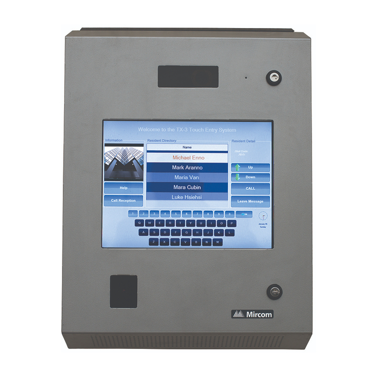
Mircom
Mircom TX3-TOUCH-S15B-WR Installation

urmet domus
urmet domus sinthesi steel 1375 instructions


